your "problem" is not going to really require much more than carefully rebuilding the carbs then correctly adjusting the throttle linkage
Ive worked on several similar systems in the past and most people are clueless, its just not that difficult if you understand what your trying to accomplish, your trying to get a totally predictable and repeatable aior flow entering each plenum, this may be rather time consuming but its not difficult if taken in stages and done in a logical manor.
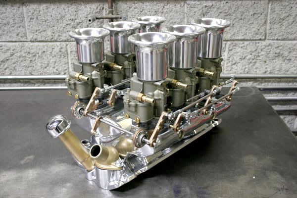
most three duce set-ups have a center carb that has an idle circuit and two outer carbs that don,t that act only like the secondary throttle bodys in a four barrel carb, this is not the case with 6 x 2 barrel cab set-ups, all six carbs will be nearly identical, and all 6 contribute to air flow and idle, this mandates you must have consistency, you can,t adjust a single carb randomly or your get more problems than you can imagine, done correctly you get a smooth powerful transition.
youll need two vacuum gauges, hook one to each plenum and use to adjust each single center carb to flow at an equal vacuum and read the plugs to verify the fuel/air ratio is close to correct.
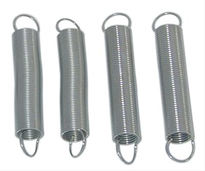
remember youll want fairly light spring return spring tension on all six individual carbs in the event of a linkage failure or breakage to help reduce the potential for a wide open throttle run-away condition should the linkage break, but you don,t want the combined spring tension to offer resistance thats going to make easy throttle petal depression noticeable
http://www.harborfreight.com/fuel-pump-and-vacuum-tester-93547.html
and a fuel pressure gauge.
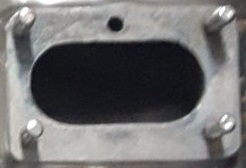
youll want too have four temporary carburetor block off plates , that you can use to test with
,these should be about 3/8" thick aluminum,
so they are not easily bent or distorted when clamped in place on the four outer carb mount locations,
(the front and rear locations on each plenum, )
almost any machine shop can make a set of four block-off plates if you give them a gasket rather in-expensively
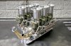
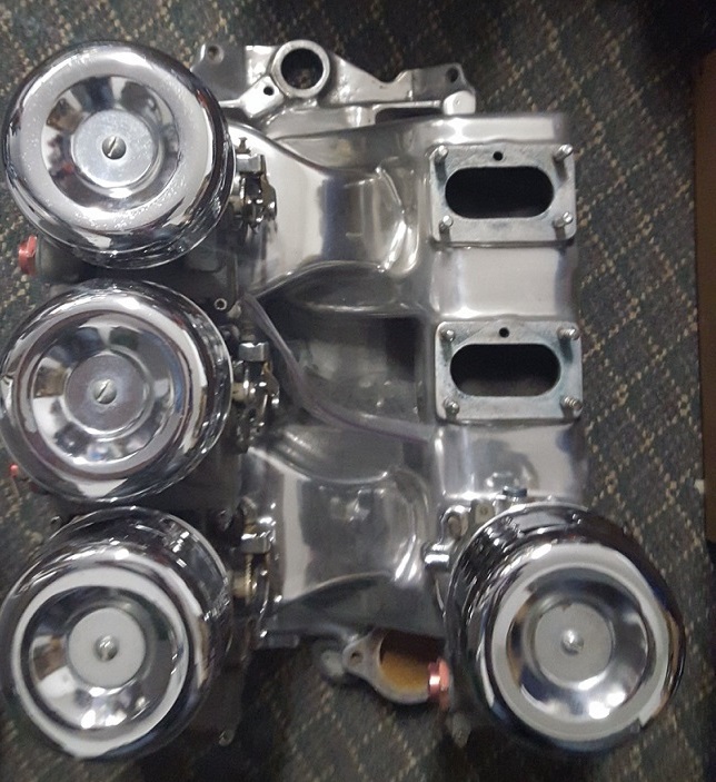
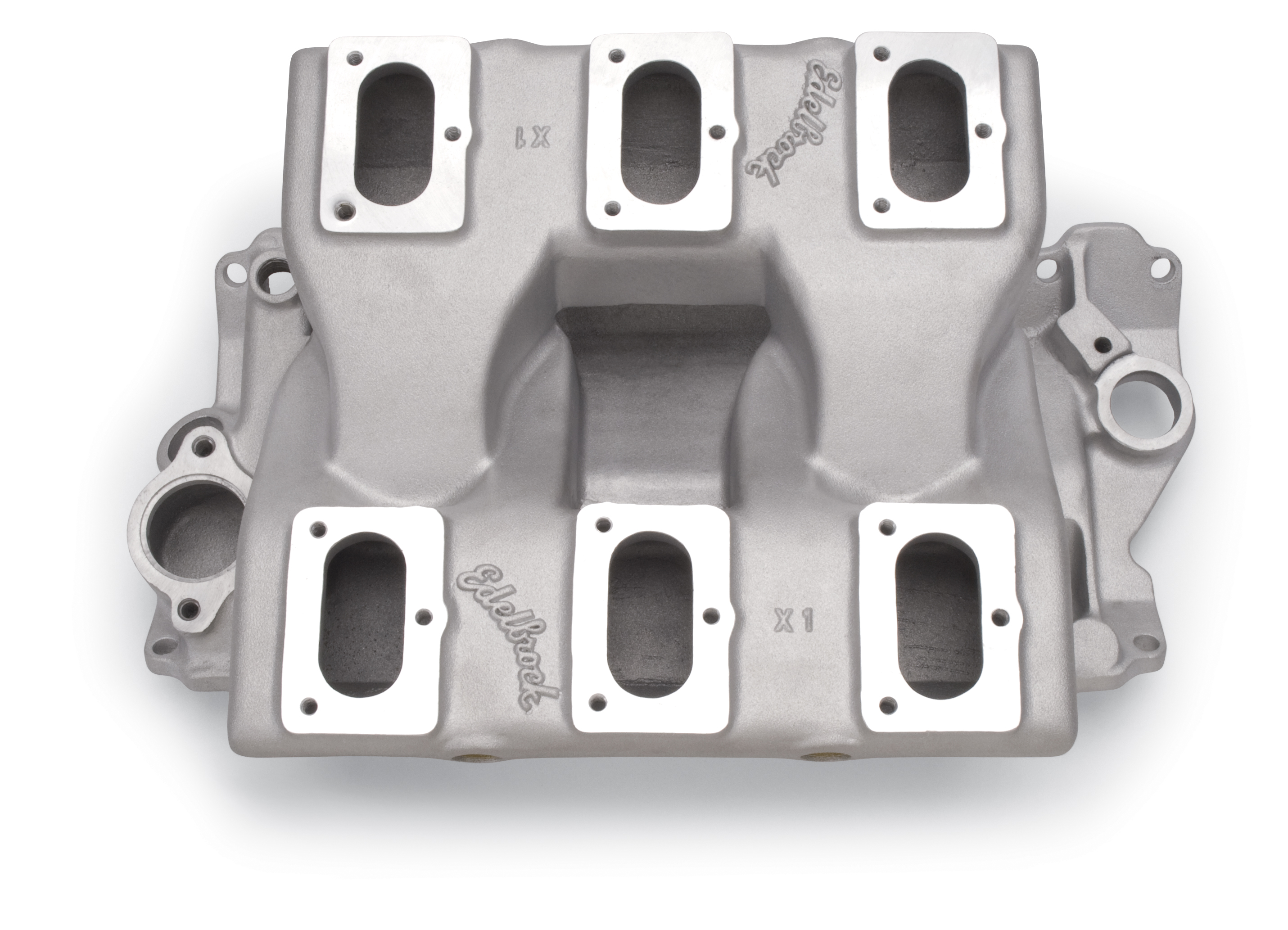
the intake basically has two similar plenums ,
P pass side plenum feeds the drivers side or odd numbered cylinder head ports
D drivers side plenum feeds the pass or even numbered side cylinder head ports
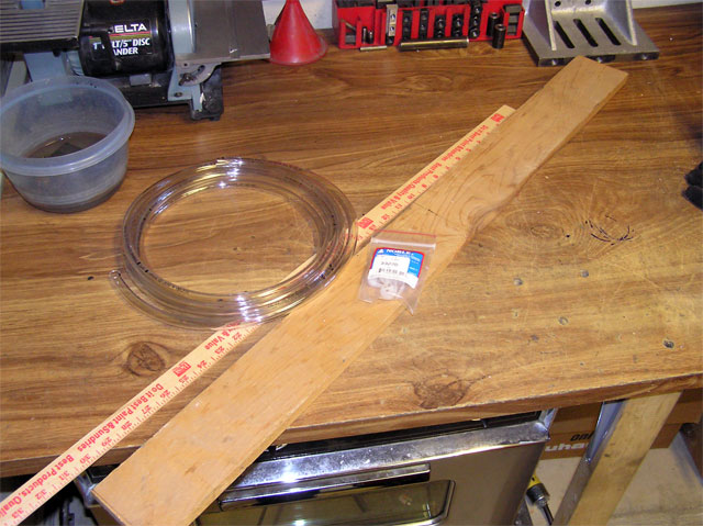
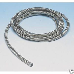
btw a yard stick, 15-20 ft of clear plastic tube , SOME FOOD DYE,
and a drill, a 3 foot section of 1x 4 wood ,ty-wraps are all thats required to build a manometer
look at link
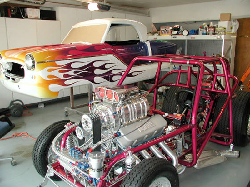
I hope that I can articulate this... so I have hopes for a well thought out and coordinated engine build. I picked up an X-1 years ago and have yet to do much with it. I just didn't have the knowledge base to execute it properly. I'm looking for some help with that. The idea is to put a small...
garage.grumpysperformance.com
READ THRU THE LINKED INFO ABOVE
you can easily fabricate a custom built MANOMETER (fancy word for a tool that allows you to balance and equalize the flow rates of the two throttle bodys on the cross fire intake manifold
STEP ONE
Shopping
Hit the local hardware store and buy 12 feet or so of 5/16” or 3/8” clear vinyl tubing. There are some photos circulating the web of a home made manometer using very thin tubing . like maybe 1/8”. If you are considering this, slap yourself or poke yourself in the eye with a sharp stick . . because that will be less painful that trying to get the bubbles out of 1/8” tubing.
Get some nylon clips to hold the tubing . . . if you are an actual genuine red-neck, you may use strips of duct tape or bent over rusty nails. For a classy read-neck manometer, splurge and get a get a $1 yardstick. Here again black marks every inch is all you really need, but the yardstick is in the budget, so go ahead, get crazy.
You need two one inch long pieces of vacuum hose . . you can buy new or snip some from your vacuum gage or from under your hood somewhere.
Some food coloring is nice, but not required. BTW, the term ‘food’ actually means “food, clothing, hands, garage floor, car body, dog and anything else nearby” coloring.
Now the tricky part is finding special ‘manometer wood’. This is rare stuff not usually available at any store. Fortunately it can often be found propped up in the corner of the average garage, origin unknown, age unknown. It comes in various sizes and is easily recognized by the brown color.
Shopping expedition should yield a bootay pile similar to this:
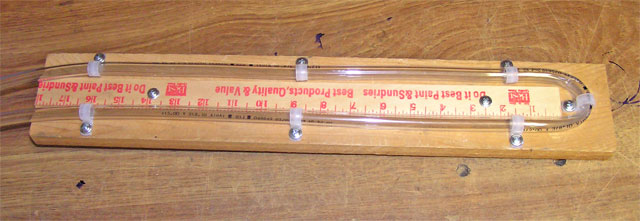
STEP TWO
Build the manometer. (i.e. arrange the bootay like so")
STEP THREE
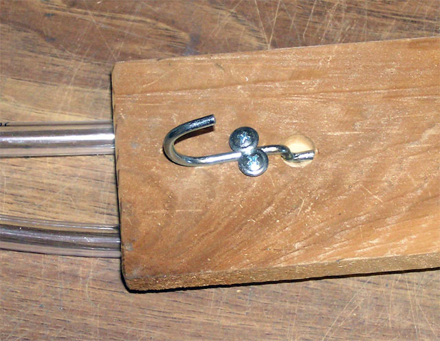
Stick the vacuum tubing into the ends of the vinyl
Hardly deserves its own step . . . OK, we’ll do the hanger too:
In keeping with the overall red-neck theme .. concoct some form of hanger. Here we see the recycled peg board hanger method.
OPTIONAL STEP
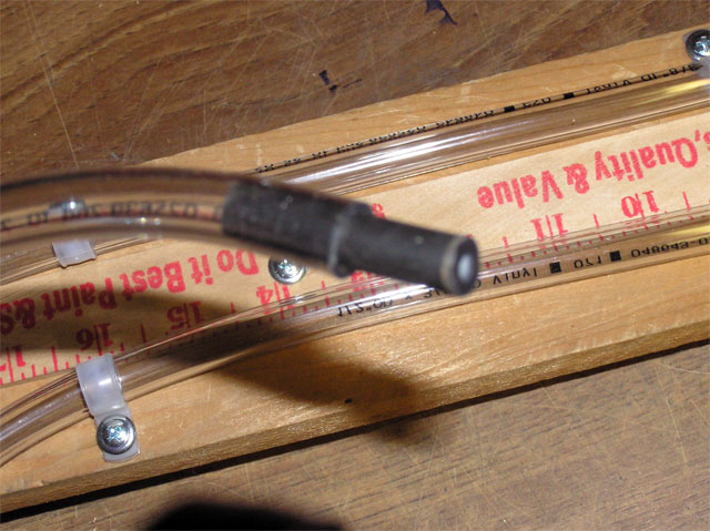
Your water manometer is exactly as accurate as anything you can buy. It is also very . . . responsive, shall we say. If you hook your manometer up to the port when it is pulling a lot of vacuum, you have .001 seconds to disconnect it before the water goes bye-bye. Don’t worry about it if it happens, It will not hurt the engine at all.
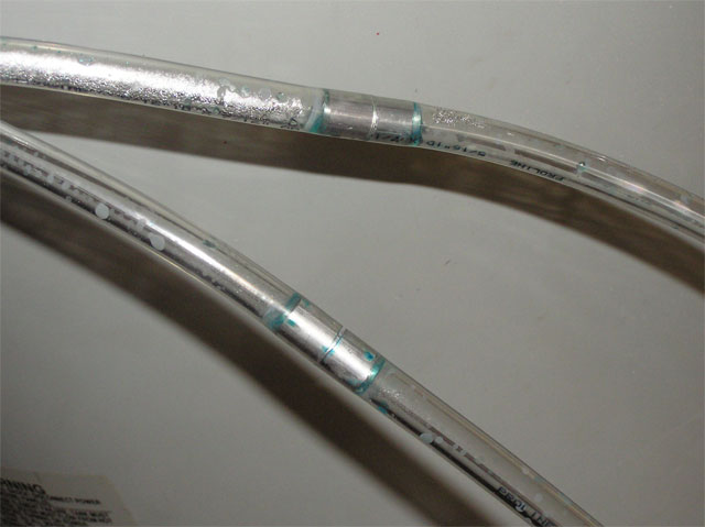
You can install restrictors in the line to dampen the response of the manometer without changing the accuracy. Any small orifice will do and it actually only has to be in one leg. I used a piece of aluminum rod with a 1/16” hole drilled thru it. I later discovered that a very small plastic wall anchor stuck into one of the pieces of vacuum tubing works almost as well.
And Viola! (that’s French for Gosh Dern!) You now have a working manometer!
STEP FOUR
Just add water.
You can mix up some food coloring in a bowl . . dip one end ogf the manometer tube in the water and suck on the other end until you get about half the manometer’s height in water sucked in. Remove the end from the bowl and hold both ends up high and the manometer will fill up nicely . . .
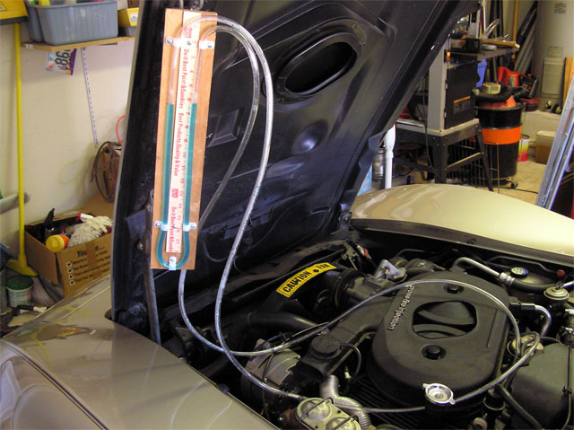
Perform a quality control test of the hanger mechanism:
(the picture above is a cross fire intake,)
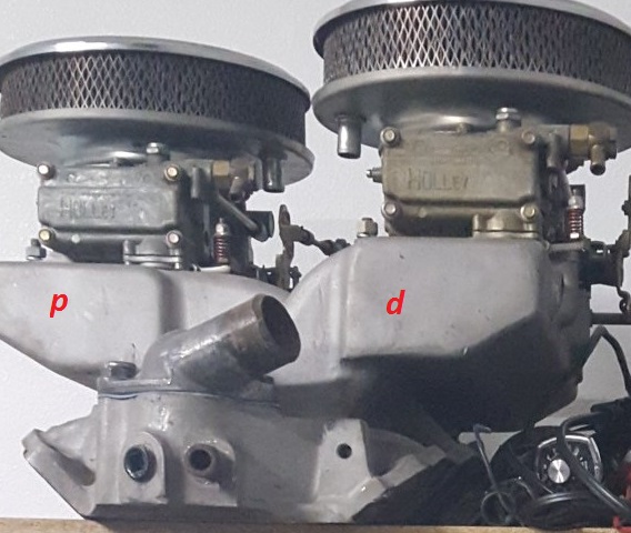
When your tuning a 6x2 barrel carb intake you use block off plates on the 4 outer carb locations to start as you'll need to verify correct function of each of the carbs individually first as a badly adjusted carb can make your ability to tune miserable, thus each of the two bank, separate plenums (D and P pictured above) is adjusted and balanced with the two outer locations on each seperate plenum blocked off, with block off plates.
consistency and repeat-ability is key, you'll want all the float levels and carb jets set identically to start
you then adjust the two center carbs, (theres only one on each plenum, at this point) to be as close to equal and balanced as you can get, first with two vacuum gauges , too get the correct adjustment close to correct, then once your close you balance the vacuum with the two plenums connected too the vacuum gauges, first, then fine tune with the manometer.
but once you balance the two plenums with Your water manometer , take notes on the idle adjustment screw,setting float levels and throttle blade locations, I generally try to get the engine to idle at the lowest rpm that will result in a reasonably steady vacuum gauge reading.
once thats done you put those two carbs back on the work bench and tag them with linen tags as correctly adjusted, and then you repeat the whole process with two more, carbs ,and get them set up as close to identical as you can too the first two, once those two are correctly set up using the center location on each plenum only, you repeat the process with the last two carbs on the center location on each plenum.
only once you have all three sets of two carbs correctly adjusted and balanced with the manometer do you install all three carbs on each plenum.
at this point youll generally find that with three carbs on each bank the engine idles at 1600rpm-1700rpm. due to all three carbs idle circuits allowing air flow into the plenum on each bank,so the 4 corner end carbs throttle blade adjustment is now each equally adjusted to a slightly more closed position, as you want the center carb on each bank to be supplying about 70% of the total air flow and each end carb about 15%, (you don,t touch the center carb on each bank)
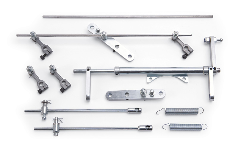
now for the throttle linkage, the center two carbs will act as primaries,
youll set up a progressive linkage
where only the two center carbs throttle blades open until the engine reaches about 3000rpm,, this requires the linkage to have slide stops on the end carb's linkage, but a firm mechanical link on the two center carb throttle shafts.
on a slowly opened throttle, at that point, in the gas petal depression, you want the 4 outer carbs (front and rear pass and front and rear drivers side carbs to start opening equally) usually at about 1/4 throttle ,and by the time the gas petals completely depressed to the floor all six carbs should be fully open
http://garage.grumpysperformance.com/index.php?threads/custom-throttle-linkage.861/#post-33717
http://www.edelbrock.com/automotive/mc/carburetors/94-series.shtml
takes a bit of experience
setting up the carb linkage correctly