Enginology: More Thoughts on Engine Airflow
Written by Jim McFarland on December 8, 2017

Discussing port volumes as a measure of evaluating potential engine performance.
Over time, we’ve used this column as a forum to discuss various aspects of engine air flow. One topic we’ve not included in these discussions has been the practice of comparing port volumes as a measure of evaluating potential engine performance. The following addresses how we feel about that yardstick for making comparisons.
First of all, air flow benches are nothing magical. They can be valuable but their limitations need to be recognized if the data they produce is to be of any value. In other words, a gain in air flow (in and of itself) will not always result in a corresponding gain in power. What these benches can provide is a stepping stone in determining the potential for an increase in power.
For a number of years, Harold Bettes and I have been friends. Both of us attended the University of Texas, having majored in mechanical engineering. Harold spent many of his career years in this industry working for and helping develop air flow measurement equipment for the Superflow Corporation. Consequently, he is well versed in the subject.
[URL='https://www.hotrod.com/articles/enginology-thoughts-engine-airflow/']In his view, knowing air flow data and how to properly use it can be helpful when making choices about a variety of engine and powertrain components, including rear gear ratios that can be linked to inlet airflow data since peak power typically occurs at or near peak air flow. Here’s an example of what that can mean.
[/URL]
On the assumption that air flow data was obtained at a flow bench depression of ten inches of water, that ignition spark has been optimized, air fuel ratios and volumetric efficiency are maximized along with combustion efficiency, a fairly accurate power estimation can be calculated as tied to the air flow data. The following is an example of that approach.
Let’s say we have a flow bench reading of 200 cfm as applied to an eight cylinder engine. The equation that follows is:
200 cfm x 0.43 = 86 x 8 cylinders = 688 hp @ peak power rpm.
However, if all the air flow data had been measured at 25 inches of water bench depression, the multiplier would change to 0.27 instead of 0.43, resulting a calculation of 432 hp at peak power rpm. If we wanted to calculate the rpm at which these estimated peak power levels would occur, a comparable mathematical approach can be used. That equation would look like:
Rpm for peak power = 2000/43.75 x 156 cfm = 7,131 rpm
In my discussions with Bettes, he pointed out that this approach makes the assumption that all air flow data is obtained using a “full” intake system that includes carburetor, intake manifold, and cylinder head to be used on the running engine.
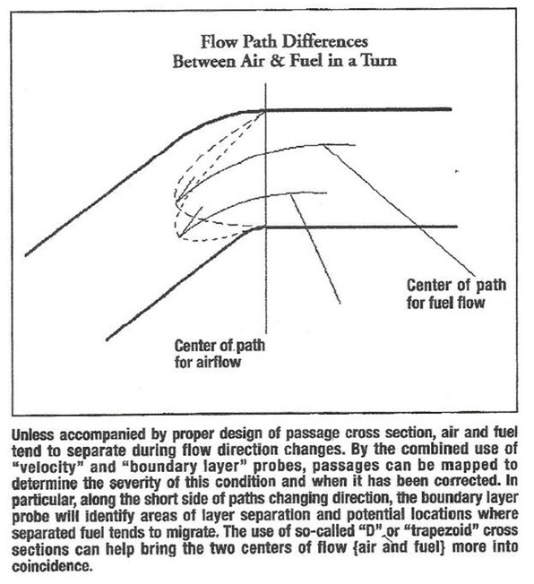
Now, you may ask, why is air flow quality so important? We’ve previously touched on this, but a few of the points bear emphasizing. For example, consider both air and fuel behave much like a compressible fluid. That is to say they can be compressed by each differs from the other on how they behave when subjected to greater or less than atmospheric pressure. Maybe the best way to discuss this is as follows.
Essentially, air is a compressible fluid. It exhibits the properties of a compressible fluid because it has viscosity that increases as a function of its flow rate (velocity). But air also tends to “stick” to the surfaces over which it passes (inlet passages, etc.). Even if efforts are taken to create either stable or controlled air flow conditions (swirl, tumble, etc.), it remains as the “working fluid” by which fuel is delivered to the combustion space. It thus becomes of value to understand some of the aspects (including benefits) of how air flow quality and quantity, especially quality.
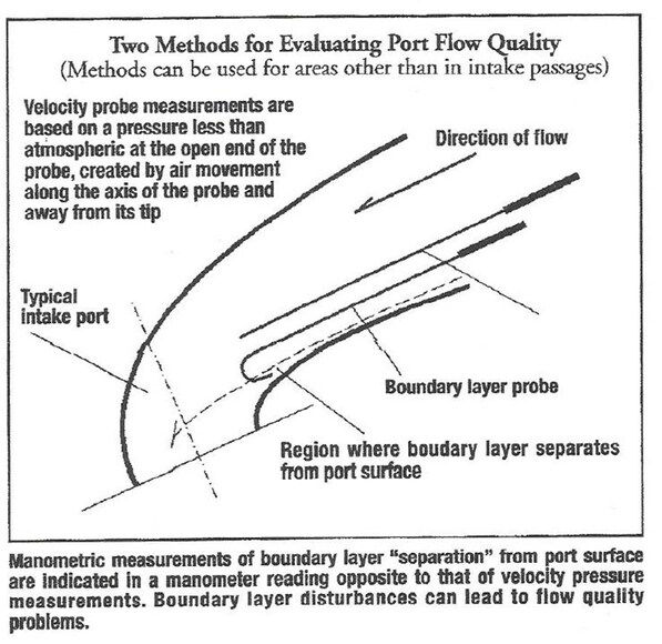
In this regard, we can return to the air flow bench for ways to get a sense for both stable and unstable inlet air flow. We’ve known some long-time flow bench operators who claim they can judge the efficiency of a given port by the sound of air. That is to say the less “noise” the port exhibits the more efficient it will perform. We prefer something more concrete than that. For that reason we’ve always relied on the use of various pressure probes (hand-held is sufficient) to locate and quantify trouble spots in the inlet path.
There are two such probes that have proven beneficial over the years of personal use of a flow bench. One we’ll call a “velocity probe” which consists of a straight, short-length of tubing of about 0.020” i.d. connected (usually with a length of plastic tubing attached to the down-stream side of a bench’s flow measurement) and the other a section of the same size tubing bent into a U-shape at its open end and connected to the same part of the bench’s measuring system. (We’ve included a sketch to illustrate the shape and location of use in a typical intake port passage, just for orientation).
The so-called “J-probe” will help identify areas where there is a potential boundary layer separation between the air and surfaces over which it is passing and the possibility of air/fuel ratio disruption and lost combustion efficiency (power). Don’t be surprised if the J-probe measured manometric data registers less than atmospheric pressure. That’s because it’s exhibiting turbulence that’s counterproductive to maintaining the desired net air fuel rations eventually in the combustion space. Once you’ve “smoothed” out the air flow this condition should be notably reduced.
Flow path surface texture is yet another factor that can have an effect on both flow quantity and quality. This is especially true on the intake side of the overall flow path where atomized fuel needs to be kept in suspension, even in port-injected applications. There is sufficient opportunity for mixture quality to be diminished from the point of fuel introduction to the time of spark ignition than to overlook the chances to improve the way it is blended with the air.
For example, while you may discover ways to “polish” the intake path to increase dry air flow, it does not necessarily follow that such conditions will not decrease the ability to keep fuel in suspension.
All this is to say that there are numerous factors that play into increasing an engine’s net air flow than “more is always better.” Keep in mind that you need to strive to creating and maintaining the proper blend (including mixture quality) as air flow is increased, because it is in the combustion space that “the proof is in the pudding.” Admittedly, that may be a bit out of place for CT but, in fact, it’s true.
By the way, you’ll note that at no point in this month’s discussion did we reference anything and port volumes as measured in cc’s. ‘Nuff said.
Written by Jim McFarland on December 8, 2017
Discussing port volumes as a measure of evaluating potential engine performance.
Over time, we’ve used this column as a forum to discuss various aspects of engine air flow. One topic we’ve not included in these discussions has been the practice of comparing port volumes as a measure of evaluating potential engine performance. The following addresses how we feel about that yardstick for making comparisons.
First of all, air flow benches are nothing magical. They can be valuable but their limitations need to be recognized if the data they produce is to be of any value. In other words, a gain in air flow (in and of itself) will not always result in a corresponding gain in power. What these benches can provide is a stepping stone in determining the potential for an increase in power.
Cheap Good Cylinder Heads
Where do you find good and cheap cylinder heads? A set of these for $280 + valves + springs, reuse old rocker arms = $400 https://www.ebay.com/itm/393005918509 https://www.ebay.com/itm/322892146731 https://garage.grumpysperformance.com/index.php?threads/sellecting-cylinder-heads.796/page-2 Buy...
garage.grumpysperformance.com
For a number of years, Harold Bettes and I have been friends. Both of us attended the University of Texas, having majored in mechanical engineering. Harold spent many of his career years in this industry working for and helping develop air flow measurement equipment for the Superflow Corporation. Consequently, he is well versed in the subject.
[URL='https://www.hotrod.com/articles/enginology-thoughts-engine-airflow/']In his view, knowing air flow data and how to properly use it can be helpful when making choices about a variety of engine and powertrain components, including rear gear ratios that can be linked to inlet airflow data since peak power typically occurs at or near peak air flow. Here’s an example of what that can mean.
[/URL]
On the assumption that air flow data was obtained at a flow bench depression of ten inches of water, that ignition spark has been optimized, air fuel ratios and volumetric efficiency are maximized along with combustion efficiency, a fairly accurate power estimation can be calculated as tied to the air flow data. The following is an example of that approach.
Let’s say we have a flow bench reading of 200 cfm as applied to an eight cylinder engine. The equation that follows is:
200 cfm x 0.43 = 86 x 8 cylinders = 688 hp @ peak power rpm.
However, if all the air flow data had been measured at 25 inches of water bench depression, the multiplier would change to 0.27 instead of 0.43, resulting a calculation of 432 hp at peak power rpm. If we wanted to calculate the rpm at which these estimated peak power levels would occur, a comparable mathematical approach can be used. That equation would look like:
Rpm for peak power = 2000/43.75 x 156 cfm = 7,131 rpm
In my discussions with Bettes, he pointed out that this approach makes the assumption that all air flow data is obtained using a “full” intake system that includes carburetor, intake manifold, and cylinder head to be used on the running engine.
Now, you may ask, why is air flow quality so important? We’ve previously touched on this, but a few of the points bear emphasizing. For example, consider both air and fuel behave much like a compressible fluid. That is to say they can be compressed by each differs from the other on how they behave when subjected to greater or less than atmospheric pressure. Maybe the best way to discuss this is as follows.
Essentially, air is a compressible fluid. It exhibits the properties of a compressible fluid because it has viscosity that increases as a function of its flow rate (velocity). But air also tends to “stick” to the surfaces over which it passes (inlet passages, etc.). Even if efforts are taken to create either stable or controlled air flow conditions (swirl, tumble, etc.), it remains as the “working fluid” by which fuel is delivered to the combustion space. It thus becomes of value to understand some of the aspects (including benefits) of how air flow quality and quantity, especially quality.
In this regard, we can return to the air flow bench for ways to get a sense for both stable and unstable inlet air flow. We’ve known some long-time flow bench operators who claim they can judge the efficiency of a given port by the sound of air. That is to say the less “noise” the port exhibits the more efficient it will perform. We prefer something more concrete than that. For that reason we’ve always relied on the use of various pressure probes (hand-held is sufficient) to locate and quantify trouble spots in the inlet path.
There are two such probes that have proven beneficial over the years of personal use of a flow bench. One we’ll call a “velocity probe” which consists of a straight, short-length of tubing of about 0.020” i.d. connected (usually with a length of plastic tubing attached to the down-stream side of a bench’s flow measurement) and the other a section of the same size tubing bent into a U-shape at its open end and connected to the same part of the bench’s measuring system. (We’ve included a sketch to illustrate the shape and location of use in a typical intake port passage, just for orientation).
The so-called “J-probe” will help identify areas where there is a potential boundary layer separation between the air and surfaces over which it is passing and the possibility of air/fuel ratio disruption and lost combustion efficiency (power). Don’t be surprised if the J-probe measured manometric data registers less than atmospheric pressure. That’s because it’s exhibiting turbulence that’s counterproductive to maintaining the desired net air fuel rations eventually in the combustion space. Once you’ve “smoothed” out the air flow this condition should be notably reduced.
Flow path surface texture is yet another factor that can have an effect on both flow quantity and quality. This is especially true on the intake side of the overall flow path where atomized fuel needs to be kept in suspension, even in port-injected applications. There is sufficient opportunity for mixture quality to be diminished from the point of fuel introduction to the time of spark ignition than to overlook the chances to improve the way it is blended with the air.
For example, while you may discover ways to “polish” the intake path to increase dry air flow, it does not necessarily follow that such conditions will not decrease the ability to keep fuel in suspension.
All this is to say that there are numerous factors that play into increasing an engine’s net air flow than “more is always better.” Keep in mind that you need to strive to creating and maintaining the proper blend (including mixture quality) as air flow is increased, because it is in the combustion space that “the proof is in the pudding.” Admittedly, that may be a bit out of place for CT but, in fact, it’s true.
By the way, you’ll note that at no point in this month’s discussion did we reference anything and port volumes as measured in cc’s. ‘Nuff said.
Last edited: