info that might help (yes ,before you ask, yeah the LT1 is very similar, and if you don,t look thru the sub links youll miss good info)
L-98 Engine Start Sequence
ALWAYS TEST ALL YOUR INJECTORS OHMS RESISTANCE, WITH A MULTI METER, IF YOUR ENGINE RUNS BADLY ,INDIVIDUALLY< THEY SHOULD ALL BE VERY CLOSE TO EQUAL, ANY THAT ARE NOT NEED TO BE REPLACED
knowing whats going on and WHY can help
http://www.corvettefever.com/techarticl ... index.html
viewtopic.php?f=55&t=1241
http://tpiparts.net/85_89_maf_sensors/
http://members.shaw.ca/corvette86/Component Location View 86.pdf
http://members.shaw.ca/corvette86/FuelSystemDiagnosis.pdf
viewtopic.php?f=50&t=609&p=5672#p5672
When you start an L-98 engine Corvette, a series of events take place that causes the engine to run. Knowing the sequence will help you troubleshoot no start conditions.
Fuel Rail Pressurization:
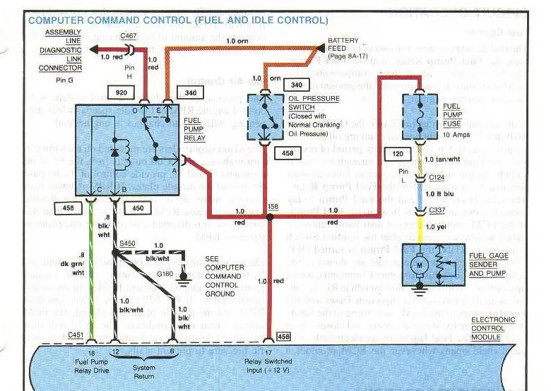
When you first turn the key to the “on†position, the fuel pump will run for 2 seconds pressurizing the fuel rails. There is a Shraeder valve on the passenger side fuel rail near the rear of the engine and if you measure the pressure there after the pump runs, you should see between 40-42 pounds of pressure. The reading will go to 38-40 pounds nominal once the engine is running.test by attaching a fuel pressure gauge to the fuel rail at the shrader valve, on TPI and LT1 engines its located on the pass side fuel rail If youve got an early year TPI , thats designed to use a 9th cold start injector,check the cold start injector as its a potential problem source if its not working correctly.
Initial Crank Action:
If you then rotate the key to the start position (assuming the anti-theft system has not disabled the starter), the engine will rotate.
Once the oil pressure has reached 4 PSI, the oil pressure switch will close allowing the fuel pump to run. (Note that you should have a black oil pressure switch/sender. It is mounted behind the distributor on the driver’s side and if it is not black, it is suspect due to a run of bad units that stayed in the GM parts pipeline for some time).
The distributor will send a string of pulses to the ECM (Engine Control Module) in response to the engine being rotated by the starter. These pulses continue as long as the engine turns (both starting and running) and if they are not present, the engine will not run.
ECM Reaction:
If the ECM sees oil pressure greater than 4 PSI and the reference pulses from the distributor, it will energize the injector drivers which will begin pulsing the injectors on for 4 ms (milliseconds) periods. (In the L98, all injectors on one side of the engine fire at the same time followed by all injectors on the other side firing at the same time. On the LT-1, the injectors are fired individually at the appropriate time).
The ECM will also pull in the fuel pump relay in effect paralleling it electrically with the oil pressure switch. (If the fuel pump relay fails, you can still normally get the car to start and run unless you can’t make at least 4 PSI oil pressure. This is a “limp home mode†feature put in place to allow for a fuel pump relay failure).
The ECM also monitors the TPS (Throttle Position Sensor mounted on the throttle body assembly) and wants to see .54 volts at this time. If it sees appreciably more than 0.54 volts, it will assume the engine is flooded and the driver has pressed the accelerator to the floor to clear the flooded condition and restrict the fuel flow as a result. (.54 volts during start and at idle from the TPS is very important to both starting and run performance.)
Assuming the ignition module is good (meaning there is a spark of sufficient intensity to ignite the fuel), the engine will “catchâ€.
Engine "Catches":
When the engine catches, the MAF (Mass Air Flow sensor mounted just ahead of the throttle body) sends a signal to the ECM advising that air is flowing and also just how much air is being pulled through to the intake manifold. The ECM takes note of the amount of air being consumed and adjusts the injector pulse width to around 2.2 ms nominally so as to attain a proper air/fuel mixture to insure combustion. (This is how the 1985 through 1989 L-98 works. For information on the 1990 and 1991 L-98 variant, see the Note below).
The engine should show an initial idle speed of around 900-1100 RPM and then slowly diminish to 600-700 RPM unless the air conditioner is on in which case it will run at around 800 RPM.
If this does not happen, the Idle Air Mixture valve (located on the throttle body) may be misadjusted. Alternatively, there may be a leak in the intake manifold or another vacuum leak may be present. Listen for hissing sounds---there should be none.
ECM Mode:
The engine will now be in Open Loop mode meaning that the ECM is controlling the air/fuel mixture by referencing values stored in memory.
Once the Oxygen sensor (mounted on the exhaust pipe) reaches operating temperature of several hundred degrees, the Manifold Air Temperature (MAT) sensor shows an intake air temperature of more than 140 degrees and the Engine Coolant Temperature (ECT) has reached 160 degrees, the computer will switch to closed loop mode meaning the Oxygen sensor’s output is examined along with the MAT and ECT outputs and the ECM adjusts the injector pulse widths (more “on time†or less “on timeâ€) to constantly strive for a 14.7:1 air/fuel mixture which is the best mixture to hold down pollution.
Note that prolonged idling can force the computer back into open loop mode.
Note: In 1990, the MAF was eliminated from the engine in favor of a speed/density system. This system uses a sensor called the MAP sensor which measures the Manifold Absolute Pressure (hence the name MAP) and compares it with the atmospheric pressure outside the intake manifold. This information, coupled with the Manifold Air Temperature, Engine Coolant Temperature and Engine RPM is used by the ECM to determine the amount of air entering the cylinders. It is a different way of reaching the desired 14.7:1 air-fuel mixture ratio but functionally is like the MAF system in that the ECM uses the feedback to control the "on time" for the injectors.
Corvette used this approach in the 1990 and 1991 L-98 engines and in the 1992 and 1993 LT-1 engines. With the 1994 model C4, they went back to the MAF system. Note that MAF based systems are far more accurate since they measure air flow directly whereas the MAP system infers air flow indirectly. A multitude of things can throw the calculation off and Corvette returned to the MAF system beginning with the 1994 C4 (with a MAP backup). From a troubleshooting standpoint, the MAP operation comes into the sequence the same place that the MAF does.
Summary:
If you have a no start condition or if the L-98 starts and then dies, check the above items in sequence to see if all the events are occurring as required.
1987 TPI
1991 TPI
A Scan Tool makes this job much easier and is a highly recommended troubleshooting aid for these sorts of problems.
http://www.harborfreight.com/cpi/ctaf/Displayitem.taf?itemnumber=46030
Most of the C4 Corvettes used a MAF (Mass Air Flow) sensor to determine how much air is being pulled into the intake manifold. The exceptions are the 1984 Corvette that used a speed density system--a sort of predictive method of measurement---and the 1990 through 1993 C4 models which were also speed density based. In 1994, Corvette went back to the MAF based system but used the speed density approach as a back up. (1989 Bosch MAF installation shown at right).
A Mass Air Flow sensor has an extremely fine wire inside its bore. The 1985 through 1989 C4 engines used a Bosch MAF sensor that heated the wire to 100 C. The 1994 and later C4 models used a AC/Delco MAF that heated the wire to 200 C. The amount of current required to reach the temperature is measured in each case. (Note: the LT-5 engine used in the ZR-1 used a speed density system and continued to use that system in 1994 and 1995 since the engines had already been made prior to the last two years of production. The ZR-1 therefore has no MAF even after Corvette went back to the MAF based system).
Theory of Operation
As the air travels past the heated wire enroute to the intake manifold, it will cool the wire and additional current is added to again heat the wire to the design temperature. Since the amount of air moving past the sensor is directly related to the amount of cooling experienced by the heated wire, a feedback condition is established whereby the exact amount of moving air is directly related to the amount of current passing through the wire and the intake air is therefore precisely measured.
Once the amount of air is known, the computer controlling the engine can add or subtract fuel as required to maintain the magic 14.7:1 air-fuel mixture resulting in the cleanest burn possible from an emissions (pollution) standpoint.
It does this by varying the "on time" of the fuel injectors. The injectors are pulsed on and off and the width of the pulse is lengthened or shortened as required. When you first start a typical engine, the pulse width is around 4 milliseconds but as soon as the engine "catches" the pulse width is shortened to about 2.2 milliseconds for idle. During operation, the measured air flow through the MAF will cause the computer to increase or decrease the pulse width as explained above.
MAF Operating Conditions
The Bosch MAF is more complex than the AC/Delco version. Both measure the air flow but the Bosch MAF has a circuit called the 'burn-off circuit' that cycles on for about 2 seconds when you shut the engine down. This circuit heats the wire to a high enough temperature to burn off any residue that may have collected on the wire during operation. If you are in a quiet area, you can hear the relays click on and then off on a 1985-1989 C4 as the burn-off cycle occurs.
There are two relays involved with the Bosch MAF: A power relay that passes current to the MAF wire during normal operation and the burn-off relay that provides the current for the cleaning cycle. Both are located on the firewall in the engine compartment, just behind the battery on the drivers side. Bad MAF power and burn-off relays can cause hard starting problems and should be changed periodically as preventative measure and any time you experience hard starting conditions.
The AC/Delco MAF has a power relay but no burn-off relay. For this reason, you should pay even closer attention to the condition of your air filter on a later model C4 than normal since a contaminated wire in a AC/Delco MAF is going to stay contaminated for the most part and cause false signals to be passed to the computer.
Also, the Bosch MAF outputs its information as a analog signal to the computer but the AC/Delco sends its signal as a digital component of varying frequency. For this reason, you cannot measure it's operation directly.
A scan tool is generally the best way to troubleshoot engine problems and with the 1994 and later Corvette, it is virtually mandatory. (An oscilloscope will also work on the AC/Delco MAF but a regular test meter will not).
MAF Problems
Faulty MAF sensors will normally light the check engine light on the drivers information center if the problem is constant and store a trouble code. If intermittent, a trouble code will still be stored as long as the battery is not disconnected.
Normally, the problem is a poor connection at the sensor and wiggling the wires, unplugging and reinserting the connector will often cure the problem.
A faulty MAF will normally cause a no start or difficult start condition and although you can eventually get the car into the "limp-home" mode in most cases, you need to attend to the problem ASAP.
this flow chart might help
http://members.shaw.ca/corvette86/FuelSystemDiagnosis.pdf
AC/Delco sensors can become intermittent or give false readings if the wires become contaminated as explained above.
The MAF is a critical part of the emission control system and as such will cause the computer to react to problems very quickly, setting trouble codes and reducing performance in ways that cannot be ignored for long.
MAF Mods
The Bosch MAF is often modified by removing the two screens that are present in the front and rear of the cylinder. Removing these screens significantly increases the air flow through them and this results in more horsepower. Removing the screens is an old trick from the Corvette Challenge days in 1988 and 1989. It does work but is illegal in many states so be advised not to do anything that will get you arrested for a pollution violation.
The AC/Delco MAF is not readily modified. It is what it is but since it is a larger diameter than the Bosch, it responds well to changing the air filter to a free flowing type such as the K&N filter.
Welcome to C4 vette codes it is very ....repeat very
important that if you are not savvy of working on your
vette ...you would be better off - taking your car to a
dealership for repairs on your trouble codes.
However if you feel that you want to dive right in ..than you
have come to the right place.First locate your car's alcl
this component is located just below the instrument panel and
to the left of the center console. Remove the plastic cover
the first two slots to your right are the A & B slots for a drawing of
the alcl module's picture is added below.
The A slot is the diagnostic slot and the B slot is the ground
slot. insert the computer key into these slots (with the engine
off) this is very important...now only put the ignition key
to on ( not start !!!) the check engine light will display a
code 12 which is one flash followed by two flashes.
this code will be flashed three times ..followed by the
trouble code stored in your car's computer.
what ever the code is it will be flashed three times.
have a paper and pencil ready and write down the
code .
code 13 =1 flash followed by 3 flashes =>oxygen sensor
code 14 =1 flash followed by 4 flashes =>coolant sensor
code 15 =1 flash followed by 5 flashes =>coolant sensor
code 21 = 2 flashes followed by 1 flash =>throttle position sensor
code 22 = 2 flashes followed by 2 flashes=> throttle position sensor
code 23 = 2 flashes followed by 3 flashes=> manifold air temp sensor
code 24 = 2 flashes followed by 4 flashes=> vehicle speed sensor
code 25 = 2 flashes followed by 5 flashes=> manifold air temp sensor
code 32 =>egr system
code 33 =>map sensor
code 34 =>maf sensor
code 35 => idle air control
code 41 => cylinder select error
code 42 => electronic spark control
code 43 => electronic spark control
code 44 => lean exhaust
code 45 => rich exhaust
code 51 => PROM
code 52 => fuel calpak
code 53 => system over voltage
code 54 => fuel pump circuit
code 55 => ecm
code 62 => oil temp
please remember that if you have the computer key installed
in the alcl and you start the engine ( you will ruin the engine's computer
)
only put the ignition to on (not to start)
If you should get a check engine soon display.. you can use
the above procedure and codes to buy the right part
or at the very least to keep from getting taken for a ride
and be made to pay hight prices for some inexpensive
module that you could have installed yourself.
You never ask a barber if you need a haircut ..
so you have to be on guard they will see you comming
a mile away.
If your engine displays a trouble code ... your engine will
go into limp mode ..it will still run but very poorly.
you might be able to reset the computer if it will not start
( just to get home ) by disconnecting both battery cables
and re-installing them ...this is not recommended ..but if
you are stranded it might help unitl you get your car home
or to a repair shop..good luck
1985 TO 1991:
Code #12: Normal No Codes.
Code #13: Open Oxygen Sensor Circuit.
Code #14: Coolant Sensor Circuit Low.
Code #15: Coolant Sensor Circuit High.
Code #21: Throttle Position Sensor High.
Code #22: Throttle Position Sensor Low.
Code #23: Manifold Air Temperature Circuit High.
Code #24: Vehicle Speed Sensor.
Code #25: Manifold Air Temperature Circuit Low.
Code #32: EGR System Failure.
Code #33: Mass Air Flow Sensor High.
Code #34: Mass Air Flow Sensor Low.
Code #36: Mas Air Flow Sensor Burn-Off Function Fault.
Code #41: Cylinder Select Error.
Code #42: Electronic Spark Timing.
Code #43: Electronic Spark Control.
Code #44: Lean Exhaust indication.
Code #45: Rich Exhaust Indication.
Code #46: Vehicle Anti Theft Fault.
Code #51: Faulty Mem-Cal.
Code #52: Fuel Calpak Missing.
Code #52(1990-91 Corvette Only): Engine Oil Temperature Sensor Low.
Code #53: System Over Voltage.
Code #54: Fuel Pump Circuit Low Voltage.
Code #55: Defective ECM.
Code #62: Engine Oil Temperature Sensor Circuit High.
ECM CODES 1992 TO 1993:
Code #12: Normal No Codes.
Code #13: Left Oxygen Sensor Circuit.
Code #14: Coolant Temperature Sensor Circuit High.
Code #15: Coolant Temperature Sensor Circuit Low.
Code #16: Opti-Spark Ignition Timing System.( Low Pulse)
Code #21: Throttle Position Sensor Circuit High.
Code #22: Throttle Position Sensor Circuit Low.
Code #23: Intake Air Temperature Sensor Circuit Low.
Code #24: Vehicle Speed Sensor Circuit.
Code #25: Intake Temperature Sensor Circuit High.
Code #26: Quad-Driver Module #1 Circuit.
Code #27: Quad-Driver Module #2 Circuit.
Code #28: Quad-Driver Module #3 Circuit.
Code #32: Exhaust Gas Recirclation Circuit.
Code #33: Manifold Absolute Pressure Sensor Circuit Low.
Code #34: Manifold Absolute Pressure Sensor Circuit High.
Code #36: Opti-Spark Ignition Timing System. (High Resolution Pulse.)
Code #41: Electronic Spark Timing Circuit Open.
Code #42: Electronic Spark Timing Circuit Grounded.
Code# 43: Electronic Spark Control Circuit.
Code #44: Left Oxygen Sensor Circuit Lean.
Code #45: Left Oxygen Sensor Circuit Rich.
Code #51: Mem-Cal Error.
Code #52: Engine Oil Temperature Sensor Circuit Low.
Code #53: System Voltage.
Code #55: Fuel Lean Monitor.
Code #56: Vacuum Sensor Circuit.
Code #61: Secondary Port Throttle Valve System.
Code #62: Engine Oil Temperature Sensor Circuit High.
Code #63: Right Oxygen Sensor Circuit Open.
Code #64: Right Oxygen Sensor Circuit Lean.
Code #65: Right Oxygen Sensor Circuit Rich.
Code #66: A/C Pressure Sensor Circuit Open.
Code #67: A/C Pressure Sensor Circuit. (Sensor or A/C Clutch Circuit Problem)
Code #68: A/C Relay Circuit Shorted.
Code #69: A/C Clutch Circuit.
Code #72: Gear Selector Switch Circuit.
CODES 1994 TO 1996:
DTC #11: Malfunction Indicator Lamp Circuit.
DTC #13: Bank #1 Heated Oxygen Sensor #1 Circuit:
DTC #14: Engine Coolant Temperature Sensor Circuit Voltage Low.
DTC #15: Engine Coolant Temperature Sensor Circuit Voltage High.
DTC #16: Distributor Ignition System Low Pulse.
DTC #18: Injector Circuit.
DTC #21: Throttle Position Sensor Circuit Voltage High.
DTC #22: Throttle Position Sensor Circuit Voltage Low.
DTC #23: Intake Temperature Sensor Circuit Voltage High.
DTC #24: Vehicle Speed Sensor Circuit.
DTC #25: Intake Air Temperature Sensor Circuit Voltage Low.
DTC #26: Evaporative Emission Canister Purge Solenoid Valve Circuit.
DTC #27: EGR Vacuum Control Signal Solenoid Valve Circuit.
DTC #28: Transmission Range Pressure Switch Assembly Fault.
DTC #29: Secondary Air Injection Pump Circuit.
DTC #32: Exhaust Gas Recalculation.
DTC #33: Manifold Absolute Pressure Sensor Circuit High.
DTC #34: Manifold Absolute Pressure Sensor Circuit Low.
DTC #36: Distributor Ignition System High Pulse.
DTC #37: Brake Switch Stuck On.
DTC #38: Brake Switch Stuck Off.
DTC #41: Ignition Control Circuit Open.
DTC #42: Ignition Control Circuit Shorted.
DTC #43: Knock Sensor Circuit.
DTC #44: Bank 1 LF Heated Oxygen Sensor #1 Circuit Lean.
DTC #45: Bank 1 LF Heated Oxygen Sensor #1 Circuit Rich.
DTC #47: Knock Sensor Circuit Or Module Missing.
DTC #48: Mass Air Flow Sensor Circuit.
DTC #50: System Voltage Low.
DTC #51: EEPROM Programming Error.
DTC #52: Engine Oil Temperature Sensor Circuit Voltage Low.
DTC #53: System Voltage Low.
DTC #55: Fuel Lean Monitor.
DTC #58: Transmission Fluid Temperature Sensor Circuit Low.
DTC #59: Transmission Fluid Temperature Sensor Circuit High.
DTC #62: Engine Oil Temperature Sensor Circuit Voltage Low.
DTC #63: Bank 2 RF Heated Oxygen Sensor #1 Circuit Open.
DTC #64: Bank 2 RF Heated Oxygen Sensor #1 Circuit Lean.
DTC #65: Bank 2 RF Heated Oxygen Sensor #1 Circuit Rich.
DTC #66: A/C Refrigerant Pressure Sensor Circuit Open.
DTC #67: A/C Pressure Sensor Circuit Sensor or A/C Clutch.
DTC #68: A/C Relay Circuit.
DTC #69: A /C Clutch Circuit.
DTC #70: A/C Clutch Relay Driver Circuit.
DTC #72: Vehicle Speed Sensor Loss.
DTC #73: Pressure Control Solenoid Circuit Current Error.
DTC #74: Traction Control System Circuit Low.
DTC #75: Transmission System Voltage Low
DTC #77: Primary Cooling Fan Relay Control Circuit.
DTC #78: Secondary Cooling Fan Relay Control Circuit.
DTC #79: Transmission Fluid Overtemp.
DTC #80: Transmission Component Slipping.
DTC #81: Transmission 2-3 Shift Solenoid Circuit.
DTC #82: Transmission 1-2 Shift Solenoid Circuit.
DTC #83: Torque Converter Solenoid Voltage High.
DTC #84: 3-2 Control Solenoid Circuit.(Auto Only).
DTC #84: 2nd And 3rd Gear Blockout Relay Control Circuit.
DTC #85: Transmission TCC Stock On.
DTC #90: Transmission TCC Solenoid Circuit.
DTC #91: One To Four Upshift Lamp(Manual Only).
DTC #97: VSS Output Circuit.
DTC #98: Tachometer Output Signal Voltage Wrong.
_________________you really can,t be effectively at playing mr-fix-it with out the correct tools
especially on the more modern cars that are computer controlled, the days of effectively tuning by ear and vacuum gauge and engine sound went out with carbs
you need a few basic tools, now the list will vary, but you can,t get by by guessing, you neet to know and test now that sensors and CPUs control engine function
heres some basic tools
be sure to get the specific manuals your car and EFI system and ignition system,require FIRST
https://www.etoolcart.com/index.asp?PageAction=VIEWPROD&ProdID=4047
while it appears to be expensive, it saves you a good deal of money in the long run compared to dealing with the local chevy dealers mechanics, and makes diagnostics far faster, I bought this for the shop and it seems to be a good investment, since between a dealers diagnostics and swapping parts that don,t need changing you could easily spend close to that on just a few problems getting sorted out
youll also want a few basic diagnostic tools
https://www.etoolcart.com/index.asp?PageAction=VIEWPROD&ProdID=4417
https://www.etoolcart.com/index.asp?PageAction=VIEWPROD&ProdID=6688
https://www.etoolcart.com/index.asp?PageAction=VIEWPROD&ProdID=2597
https://www.etoolcart.com/index.asp?PageAction=VIEWPROD&ProdID=8108
and a book or two
http://www.amazon.com/gp/product/0837608...ce&n=283155
http://www.amazon.com/gp/product/0879387...ce&n=283155
http://www.amazon.com/gp/product/0760304...ce&n=283155
in no time youll be the area wizz kid on chevy injection diagnostics
This is from http://shbox.com/
A fuel pressure test gauge can be bought at your local auto supply for ~$35. Attach it to the schrader valve that is on the fuel rail. Schrader valve location on 1994-1997
Normal pressure when the engine is not running and lines have been pressurized is 41-47 psi. This same pressure should be observed at wide open throttle (WOT). WOT can be simulated by removing the vacuum hose to the regulator at idle. At idle (because of the effect of the vacuum to the regulator) pressure will be less than what you observe with the vacuum line off. There may be anything from a 3 to 10 psi difference. NOTE: any indication of fuel in the vacuum line to the regulator, means the regulator is leaking and should be replaced. Check the line for fuel or the smell of fuel.
To fully determine that you don't have a pressure drop off during actual WOT situations, you should tape the gauge to your windshield and take it for a test run. This will tell you if the pump can meet actual fuel flow demands at pressure and not just at a simulated WOT condition (as when removing the vacuum to the regulator).
When you have a gauge connected and the pressure looks initially good and then bleeds off quickly when you shut the engine off, you can do a couple of tests to help you figure out where the pressure loss is.
What the factory manual says to temporarily install, is a set of "fuel line shut off adapters" (probably something the normal guy is not going to have available). You remove the fuel lines from the rail and connect these valves in between. This lets you shut off either side of the lines for testing.
You can do the same thing by pinching the flexible lines to shut them off, but risk breaking them. You might be able to do it (your risk) by using a needle nose vise grips and putting some scrap hose as cushions on the jaws. Then use that to clamp off the line just enough to seal it. Obviously, this is not the best way to shut off the lines and could result in breakage. Heat and age can make the hoses brittle. If you don't want to risk it, don't. It's just a suggestion.
You can use the fuel pump prime connector for pressurizing the system (jumper 12v to it to run the pump).
Watch your gauge as you jumper the prime connector. When you have good pressure remove the jumper and clamp off (or use shut off valve) the fuel supply line (3/8 pipe). If pressure holds, you have a leak on the feed line somewhere before it gets to the clamp (or shut off valve) or at the check ball in the pump. If it still goes down, release your clamp (or open shut off valve). Pressurize the system again, then remove the jumper and this time clamp (or shut off) the return line (5/16 line). If pressure holds, then the regulator is faulty. If pressure does not hold, you need to locate leaky injector(s). If you can't tell a leaky injector from reading the plugs, you can look and see if injectors are leaking by removing the fuel rail screws and pull the rail and all the injectors up, so you can see under them. Leave them over the injector ports. Pressurized the system and look under the injectors to see if any are dripping.
swapping info
http://www.vetteweb.com/tech/vemp_0607_ ... _test.html
L-98 Engine Start Sequence
ALWAYS TEST ALL YOUR INJECTORS OHMS RESISTANCE, WITH A MULTI METER, IF YOUR ENGINE RUNS BADLY ,INDIVIDUALLY< THEY SHOULD ALL BE VERY CLOSE TO EQUAL, ANY THAT ARE NOT NEED TO BE REPLACED
knowing whats going on and WHY can help
http://www.corvettefever.com/techarticl ... index.html
viewtopic.php?f=55&t=1241
http://tpiparts.net/85_89_maf_sensors/
http://members.shaw.ca/corvette86/Component Location View 86.pdf
http://members.shaw.ca/corvette86/FuelSystemDiagnosis.pdf
viewtopic.php?f=50&t=609&p=5672#p5672
When you start an L-98 engine Corvette, a series of events take place that causes the engine to run. Knowing the sequence will help you troubleshoot no start conditions.
Fuel Rail Pressurization:
When you first turn the key to the “on†position, the fuel pump will run for 2 seconds pressurizing the fuel rails. There is a Shraeder valve on the passenger side fuel rail near the rear of the engine and if you measure the pressure there after the pump runs, you should see between 40-42 pounds of pressure. The reading will go to 38-40 pounds nominal once the engine is running.test by attaching a fuel pressure gauge to the fuel rail at the shrader valve, on TPI and LT1 engines its located on the pass side fuel rail If youve got an early year TPI , thats designed to use a 9th cold start injector,check the cold start injector as its a potential problem source if its not working correctly.
Initial Crank Action:
If you then rotate the key to the start position (assuming the anti-theft system has not disabled the starter), the engine will rotate.
Once the oil pressure has reached 4 PSI, the oil pressure switch will close allowing the fuel pump to run. (Note that you should have a black oil pressure switch/sender. It is mounted behind the distributor on the driver’s side and if it is not black, it is suspect due to a run of bad units that stayed in the GM parts pipeline for some time).
The distributor will send a string of pulses to the ECM (Engine Control Module) in response to the engine being rotated by the starter. These pulses continue as long as the engine turns (both starting and running) and if they are not present, the engine will not run.
ECM Reaction:
If the ECM sees oil pressure greater than 4 PSI and the reference pulses from the distributor, it will energize the injector drivers which will begin pulsing the injectors on for 4 ms (milliseconds) periods. (In the L98, all injectors on one side of the engine fire at the same time followed by all injectors on the other side firing at the same time. On the LT-1, the injectors are fired individually at the appropriate time).
The ECM will also pull in the fuel pump relay in effect paralleling it electrically with the oil pressure switch. (If the fuel pump relay fails, you can still normally get the car to start and run unless you can’t make at least 4 PSI oil pressure. This is a “limp home mode†feature put in place to allow for a fuel pump relay failure).
The ECM also monitors the TPS (Throttle Position Sensor mounted on the throttle body assembly) and wants to see .54 volts at this time. If it sees appreciably more than 0.54 volts, it will assume the engine is flooded and the driver has pressed the accelerator to the floor to clear the flooded condition and restrict the fuel flow as a result. (.54 volts during start and at idle from the TPS is very important to both starting and run performance.)
Assuming the ignition module is good (meaning there is a spark of sufficient intensity to ignite the fuel), the engine will “catchâ€.
Engine "Catches":
When the engine catches, the MAF (Mass Air Flow sensor mounted just ahead of the throttle body) sends a signal to the ECM advising that air is flowing and also just how much air is being pulled through to the intake manifold. The ECM takes note of the amount of air being consumed and adjusts the injector pulse width to around 2.2 ms nominally so as to attain a proper air/fuel mixture to insure combustion. (This is how the 1985 through 1989 L-98 works. For information on the 1990 and 1991 L-98 variant, see the Note below).
The engine should show an initial idle speed of around 900-1100 RPM and then slowly diminish to 600-700 RPM unless the air conditioner is on in which case it will run at around 800 RPM.
If this does not happen, the Idle Air Mixture valve (located on the throttle body) may be misadjusted. Alternatively, there may be a leak in the intake manifold or another vacuum leak may be present. Listen for hissing sounds---there should be none.
ECM Mode:
The engine will now be in Open Loop mode meaning that the ECM is controlling the air/fuel mixture by referencing values stored in memory.
Once the Oxygen sensor (mounted on the exhaust pipe) reaches operating temperature of several hundred degrees, the Manifold Air Temperature (MAT) sensor shows an intake air temperature of more than 140 degrees and the Engine Coolant Temperature (ECT) has reached 160 degrees, the computer will switch to closed loop mode meaning the Oxygen sensor’s output is examined along with the MAT and ECT outputs and the ECM adjusts the injector pulse widths (more “on time†or less “on timeâ€) to constantly strive for a 14.7:1 air/fuel mixture which is the best mixture to hold down pollution.
Note that prolonged idling can force the computer back into open loop mode.
Note: In 1990, the MAF was eliminated from the engine in favor of a speed/density system. This system uses a sensor called the MAP sensor which measures the Manifold Absolute Pressure (hence the name MAP) and compares it with the atmospheric pressure outside the intake manifold. This information, coupled with the Manifold Air Temperature, Engine Coolant Temperature and Engine RPM is used by the ECM to determine the amount of air entering the cylinders. It is a different way of reaching the desired 14.7:1 air-fuel mixture ratio but functionally is like the MAF system in that the ECM uses the feedback to control the "on time" for the injectors.
Corvette used this approach in the 1990 and 1991 L-98 engines and in the 1992 and 1993 LT-1 engines. With the 1994 model C4, they went back to the MAF system. Note that MAF based systems are far more accurate since they measure air flow directly whereas the MAP system infers air flow indirectly. A multitude of things can throw the calculation off and Corvette returned to the MAF system beginning with the 1994 C4 (with a MAP backup). From a troubleshooting standpoint, the MAP operation comes into the sequence the same place that the MAF does.
Summary:
If you have a no start condition or if the L-98 starts and then dies, check the above items in sequence to see if all the events are occurring as required.
1987 TPI
1991 TPI
A Scan Tool makes this job much easier and is a highly recommended troubleshooting aid for these sorts of problems.
http://www.harborfreight.com/cpi/ctaf/Displayitem.taf?itemnumber=46030
Most of the C4 Corvettes used a MAF (Mass Air Flow) sensor to determine how much air is being pulled into the intake manifold. The exceptions are the 1984 Corvette that used a speed density system--a sort of predictive method of measurement---and the 1990 through 1993 C4 models which were also speed density based. In 1994, Corvette went back to the MAF based system but used the speed density approach as a back up. (1989 Bosch MAF installation shown at right).
A Mass Air Flow sensor has an extremely fine wire inside its bore. The 1985 through 1989 C4 engines used a Bosch MAF sensor that heated the wire to 100 C. The 1994 and later C4 models used a AC/Delco MAF that heated the wire to 200 C. The amount of current required to reach the temperature is measured in each case. (Note: the LT-5 engine used in the ZR-1 used a speed density system and continued to use that system in 1994 and 1995 since the engines had already been made prior to the last two years of production. The ZR-1 therefore has no MAF even after Corvette went back to the MAF based system).
Theory of Operation
As the air travels past the heated wire enroute to the intake manifold, it will cool the wire and additional current is added to again heat the wire to the design temperature. Since the amount of air moving past the sensor is directly related to the amount of cooling experienced by the heated wire, a feedback condition is established whereby the exact amount of moving air is directly related to the amount of current passing through the wire and the intake air is therefore precisely measured.
Once the amount of air is known, the computer controlling the engine can add or subtract fuel as required to maintain the magic 14.7:1 air-fuel mixture resulting in the cleanest burn possible from an emissions (pollution) standpoint.
It does this by varying the "on time" of the fuel injectors. The injectors are pulsed on and off and the width of the pulse is lengthened or shortened as required. When you first start a typical engine, the pulse width is around 4 milliseconds but as soon as the engine "catches" the pulse width is shortened to about 2.2 milliseconds for idle. During operation, the measured air flow through the MAF will cause the computer to increase or decrease the pulse width as explained above.
MAF Operating Conditions
The Bosch MAF is more complex than the AC/Delco version. Both measure the air flow but the Bosch MAF has a circuit called the 'burn-off circuit' that cycles on for about 2 seconds when you shut the engine down. This circuit heats the wire to a high enough temperature to burn off any residue that may have collected on the wire during operation. If you are in a quiet area, you can hear the relays click on and then off on a 1985-1989 C4 as the burn-off cycle occurs.
There are two relays involved with the Bosch MAF: A power relay that passes current to the MAF wire during normal operation and the burn-off relay that provides the current for the cleaning cycle. Both are located on the firewall in the engine compartment, just behind the battery on the drivers side. Bad MAF power and burn-off relays can cause hard starting problems and should be changed periodically as preventative measure and any time you experience hard starting conditions.
The AC/Delco MAF has a power relay but no burn-off relay. For this reason, you should pay even closer attention to the condition of your air filter on a later model C4 than normal since a contaminated wire in a AC/Delco MAF is going to stay contaminated for the most part and cause false signals to be passed to the computer.
Also, the Bosch MAF outputs its information as a analog signal to the computer but the AC/Delco sends its signal as a digital component of varying frequency. For this reason, you cannot measure it's operation directly.
A scan tool is generally the best way to troubleshoot engine problems and with the 1994 and later Corvette, it is virtually mandatory. (An oscilloscope will also work on the AC/Delco MAF but a regular test meter will not).
MAF Problems
Faulty MAF sensors will normally light the check engine light on the drivers information center if the problem is constant and store a trouble code. If intermittent, a trouble code will still be stored as long as the battery is not disconnected.
Normally, the problem is a poor connection at the sensor and wiggling the wires, unplugging and reinserting the connector will often cure the problem.
A faulty MAF will normally cause a no start or difficult start condition and although you can eventually get the car into the "limp-home" mode in most cases, you need to attend to the problem ASAP.
this flow chart might help
http://members.shaw.ca/corvette86/FuelSystemDiagnosis.pdf
AC/Delco sensors can become intermittent or give false readings if the wires become contaminated as explained above.
The MAF is a critical part of the emission control system and as such will cause the computer to react to problems very quickly, setting trouble codes and reducing performance in ways that cannot be ignored for long.
MAF Mods
The Bosch MAF is often modified by removing the two screens that are present in the front and rear of the cylinder. Removing these screens significantly increases the air flow through them and this results in more horsepower. Removing the screens is an old trick from the Corvette Challenge days in 1988 and 1989. It does work but is illegal in many states so be advised not to do anything that will get you arrested for a pollution violation.
The AC/Delco MAF is not readily modified. It is what it is but since it is a larger diameter than the Bosch, it responds well to changing the air filter to a free flowing type such as the K&N filter.
Welcome to C4 vette codes it is very ....repeat very
important that if you are not savvy of working on your
vette ...you would be better off - taking your car to a
dealership for repairs on your trouble codes.
However if you feel that you want to dive right in ..than you
have come to the right place.First locate your car's alcl
this component is located just below the instrument panel and
to the left of the center console. Remove the plastic cover
the first two slots to your right are the A & B slots for a drawing of
the alcl module's picture is added below.
The A slot is the diagnostic slot and the B slot is the ground
slot. insert the computer key into these slots (with the engine
off) this is very important...now only put the ignition key
to on ( not start !!!) the check engine light will display a
code 12 which is one flash followed by two flashes.
this code will be flashed three times ..followed by the
trouble code stored in your car's computer.
what ever the code is it will be flashed three times.
have a paper and pencil ready and write down the
code .
code 13 =1 flash followed by 3 flashes =>oxygen sensor
code 14 =1 flash followed by 4 flashes =>coolant sensor
code 15 =1 flash followed by 5 flashes =>coolant sensor
code 21 = 2 flashes followed by 1 flash =>throttle position sensor
code 22 = 2 flashes followed by 2 flashes=> throttle position sensor
code 23 = 2 flashes followed by 3 flashes=> manifold air temp sensor
code 24 = 2 flashes followed by 4 flashes=> vehicle speed sensor
code 25 = 2 flashes followed by 5 flashes=> manifold air temp sensor
code 32 =>egr system
code 33 =>map sensor
code 34 =>maf sensor
code 35 => idle air control
code 41 => cylinder select error
code 42 => electronic spark control
code 43 => electronic spark control
code 44 => lean exhaust
code 45 => rich exhaust
code 51 => PROM
code 52 => fuel calpak
code 53 => system over voltage
code 54 => fuel pump circuit
code 55 => ecm
code 62 => oil temp
please remember that if you have the computer key installed
in the alcl and you start the engine ( you will ruin the engine's computer
)
only put the ignition to on (not to start)
If you should get a check engine soon display.. you can use
the above procedure and codes to buy the right part
or at the very least to keep from getting taken for a ride
and be made to pay hight prices for some inexpensive
module that you could have installed yourself.
You never ask a barber if you need a haircut ..
so you have to be on guard they will see you comming
a mile away.
If your engine displays a trouble code ... your engine will
go into limp mode ..it will still run but very poorly.
you might be able to reset the computer if it will not start
( just to get home ) by disconnecting both battery cables
and re-installing them ...this is not recommended ..but if
you are stranded it might help unitl you get your car home
or to a repair shop..good luck
1985 TO 1991:
Code #12: Normal No Codes.
Code #13: Open Oxygen Sensor Circuit.
Code #14: Coolant Sensor Circuit Low.
Code #15: Coolant Sensor Circuit High.
Code #21: Throttle Position Sensor High.
Code #22: Throttle Position Sensor Low.
Code #23: Manifold Air Temperature Circuit High.
Code #24: Vehicle Speed Sensor.
Code #25: Manifold Air Temperature Circuit Low.
Code #32: EGR System Failure.
Code #33: Mass Air Flow Sensor High.
Code #34: Mass Air Flow Sensor Low.
Code #36: Mas Air Flow Sensor Burn-Off Function Fault.
Code #41: Cylinder Select Error.
Code #42: Electronic Spark Timing.
Code #43: Electronic Spark Control.
Code #44: Lean Exhaust indication.
Code #45: Rich Exhaust Indication.
Code #46: Vehicle Anti Theft Fault.
Code #51: Faulty Mem-Cal.
Code #52: Fuel Calpak Missing.
Code #52(1990-91 Corvette Only): Engine Oil Temperature Sensor Low.
Code #53: System Over Voltage.
Code #54: Fuel Pump Circuit Low Voltage.
Code #55: Defective ECM.
Code #62: Engine Oil Temperature Sensor Circuit High.
ECM CODES 1992 TO 1993:
Code #12: Normal No Codes.
Code #13: Left Oxygen Sensor Circuit.
Code #14: Coolant Temperature Sensor Circuit High.
Code #15: Coolant Temperature Sensor Circuit Low.
Code #16: Opti-Spark Ignition Timing System.( Low Pulse)
Code #21: Throttle Position Sensor Circuit High.
Code #22: Throttle Position Sensor Circuit Low.
Code #23: Intake Air Temperature Sensor Circuit Low.
Code #24: Vehicle Speed Sensor Circuit.
Code #25: Intake Temperature Sensor Circuit High.
Code #26: Quad-Driver Module #1 Circuit.
Code #27: Quad-Driver Module #2 Circuit.
Code #28: Quad-Driver Module #3 Circuit.
Code #32: Exhaust Gas Recirclation Circuit.
Code #33: Manifold Absolute Pressure Sensor Circuit Low.
Code #34: Manifold Absolute Pressure Sensor Circuit High.
Code #36: Opti-Spark Ignition Timing System. (High Resolution Pulse.)
Code #41: Electronic Spark Timing Circuit Open.
Code #42: Electronic Spark Timing Circuit Grounded.
Code# 43: Electronic Spark Control Circuit.
Code #44: Left Oxygen Sensor Circuit Lean.
Code #45: Left Oxygen Sensor Circuit Rich.
Code #51: Mem-Cal Error.
Code #52: Engine Oil Temperature Sensor Circuit Low.
Code #53: System Voltage.
Code #55: Fuel Lean Monitor.
Code #56: Vacuum Sensor Circuit.
Code #61: Secondary Port Throttle Valve System.
Code #62: Engine Oil Temperature Sensor Circuit High.
Code #63: Right Oxygen Sensor Circuit Open.
Code #64: Right Oxygen Sensor Circuit Lean.
Code #65: Right Oxygen Sensor Circuit Rich.
Code #66: A/C Pressure Sensor Circuit Open.
Code #67: A/C Pressure Sensor Circuit. (Sensor or A/C Clutch Circuit Problem)
Code #68: A/C Relay Circuit Shorted.
Code #69: A/C Clutch Circuit.
Code #72: Gear Selector Switch Circuit.
CODES 1994 TO 1996:
DTC #11: Malfunction Indicator Lamp Circuit.
DTC #13: Bank #1 Heated Oxygen Sensor #1 Circuit:
DTC #14: Engine Coolant Temperature Sensor Circuit Voltage Low.
DTC #15: Engine Coolant Temperature Sensor Circuit Voltage High.
DTC #16: Distributor Ignition System Low Pulse.
DTC #18: Injector Circuit.
DTC #21: Throttle Position Sensor Circuit Voltage High.
DTC #22: Throttle Position Sensor Circuit Voltage Low.
DTC #23: Intake Temperature Sensor Circuit Voltage High.
DTC #24: Vehicle Speed Sensor Circuit.
DTC #25: Intake Air Temperature Sensor Circuit Voltage Low.
DTC #26: Evaporative Emission Canister Purge Solenoid Valve Circuit.
DTC #27: EGR Vacuum Control Signal Solenoid Valve Circuit.
DTC #28: Transmission Range Pressure Switch Assembly Fault.
DTC #29: Secondary Air Injection Pump Circuit.
DTC #32: Exhaust Gas Recalculation.
DTC #33: Manifold Absolute Pressure Sensor Circuit High.
DTC #34: Manifold Absolute Pressure Sensor Circuit Low.
DTC #36: Distributor Ignition System High Pulse.
DTC #37: Brake Switch Stuck On.
DTC #38: Brake Switch Stuck Off.
DTC #41: Ignition Control Circuit Open.
DTC #42: Ignition Control Circuit Shorted.
DTC #43: Knock Sensor Circuit.
DTC #44: Bank 1 LF Heated Oxygen Sensor #1 Circuit Lean.
DTC #45: Bank 1 LF Heated Oxygen Sensor #1 Circuit Rich.
DTC #47: Knock Sensor Circuit Or Module Missing.
DTC #48: Mass Air Flow Sensor Circuit.
DTC #50: System Voltage Low.
DTC #51: EEPROM Programming Error.
DTC #52: Engine Oil Temperature Sensor Circuit Voltage Low.
DTC #53: System Voltage Low.
DTC #55: Fuel Lean Monitor.
DTC #58: Transmission Fluid Temperature Sensor Circuit Low.
DTC #59: Transmission Fluid Temperature Sensor Circuit High.
DTC #62: Engine Oil Temperature Sensor Circuit Voltage Low.
DTC #63: Bank 2 RF Heated Oxygen Sensor #1 Circuit Open.
DTC #64: Bank 2 RF Heated Oxygen Sensor #1 Circuit Lean.
DTC #65: Bank 2 RF Heated Oxygen Sensor #1 Circuit Rich.
DTC #66: A/C Refrigerant Pressure Sensor Circuit Open.
DTC #67: A/C Pressure Sensor Circuit Sensor or A/C Clutch.
DTC #68: A/C Relay Circuit.
DTC #69: A /C Clutch Circuit.
DTC #70: A/C Clutch Relay Driver Circuit.
DTC #72: Vehicle Speed Sensor Loss.
DTC #73: Pressure Control Solenoid Circuit Current Error.
DTC #74: Traction Control System Circuit Low.
DTC #75: Transmission System Voltage Low
DTC #77: Primary Cooling Fan Relay Control Circuit.
DTC #78: Secondary Cooling Fan Relay Control Circuit.
DTC #79: Transmission Fluid Overtemp.
DTC #80: Transmission Component Slipping.
DTC #81: Transmission 2-3 Shift Solenoid Circuit.
DTC #82: Transmission 1-2 Shift Solenoid Circuit.
DTC #83: Torque Converter Solenoid Voltage High.
DTC #84: 3-2 Control Solenoid Circuit.(Auto Only).
DTC #84: 2nd And 3rd Gear Blockout Relay Control Circuit.
DTC #85: Transmission TCC Stock On.
DTC #90: Transmission TCC Solenoid Circuit.
DTC #91: One To Four Upshift Lamp(Manual Only).
DTC #97: VSS Output Circuit.
DTC #98: Tachometer Output Signal Voltage Wrong.
_________________you really can,t be effectively at playing mr-fix-it with out the correct tools
especially on the more modern cars that are computer controlled, the days of effectively tuning by ear and vacuum gauge and engine sound went out with carbs
you need a few basic tools, now the list will vary, but you can,t get by by guessing, you neet to know and test now that sensors and CPUs control engine function
heres some basic tools
be sure to get the specific manuals your car and EFI system and ignition system,require FIRST
https://www.etoolcart.com/index.asp?PageAction=VIEWPROD&ProdID=4047
while it appears to be expensive, it saves you a good deal of money in the long run compared to dealing with the local chevy dealers mechanics, and makes diagnostics far faster, I bought this for the shop and it seems to be a good investment, since between a dealers diagnostics and swapping parts that don,t need changing you could easily spend close to that on just a few problems getting sorted out
youll also want a few basic diagnostic tools
https://www.etoolcart.com/index.asp?PageAction=VIEWPROD&ProdID=4417
https://www.etoolcart.com/index.asp?PageAction=VIEWPROD&ProdID=6688
https://www.etoolcart.com/index.asp?PageAction=VIEWPROD&ProdID=2597
https://www.etoolcart.com/index.asp?PageAction=VIEWPROD&ProdID=8108
and a book or two
http://www.amazon.com/gp/product/0837608...ce&n=283155
http://www.amazon.com/gp/product/0879387...ce&n=283155
http://www.amazon.com/gp/product/0760304...ce&n=283155
in no time youll be the area wizz kid on chevy injection diagnostics
This is from http://shbox.com/
A fuel pressure test gauge can be bought at your local auto supply for ~$35. Attach it to the schrader valve that is on the fuel rail. Schrader valve location on 1994-1997
Normal pressure when the engine is not running and lines have been pressurized is 41-47 psi. This same pressure should be observed at wide open throttle (WOT). WOT can be simulated by removing the vacuum hose to the regulator at idle. At idle (because of the effect of the vacuum to the regulator) pressure will be less than what you observe with the vacuum line off. There may be anything from a 3 to 10 psi difference. NOTE: any indication of fuel in the vacuum line to the regulator, means the regulator is leaking and should be replaced. Check the line for fuel or the smell of fuel.
To fully determine that you don't have a pressure drop off during actual WOT situations, you should tape the gauge to your windshield and take it for a test run. This will tell you if the pump can meet actual fuel flow demands at pressure and not just at a simulated WOT condition (as when removing the vacuum to the regulator).
When you have a gauge connected and the pressure looks initially good and then bleeds off quickly when you shut the engine off, you can do a couple of tests to help you figure out where the pressure loss is.
What the factory manual says to temporarily install, is a set of "fuel line shut off adapters" (probably something the normal guy is not going to have available). You remove the fuel lines from the rail and connect these valves in between. This lets you shut off either side of the lines for testing.
You can do the same thing by pinching the flexible lines to shut them off, but risk breaking them. You might be able to do it (your risk) by using a needle nose vise grips and putting some scrap hose as cushions on the jaws. Then use that to clamp off the line just enough to seal it. Obviously, this is not the best way to shut off the lines and could result in breakage. Heat and age can make the hoses brittle. If you don't want to risk it, don't. It's just a suggestion.
You can use the fuel pump prime connector for pressurizing the system (jumper 12v to it to run the pump).
Watch your gauge as you jumper the prime connector. When you have good pressure remove the jumper and clamp off (or use shut off valve) the fuel supply line (3/8 pipe). If pressure holds, you have a leak on the feed line somewhere before it gets to the clamp (or shut off valve) or at the check ball in the pump. If it still goes down, release your clamp (or open shut off valve). Pressurize the system again, then remove the jumper and this time clamp (or shut off) the return line (5/16 line). If pressure holds, then the regulator is faulty. If pressure does not hold, you need to locate leaky injector(s). If you can't tell a leaky injector from reading the plugs, you can look and see if injectors are leaking by removing the fuel rail screws and pull the rail and all the injectors up, so you can see under them. Leave them over the injector ports. Pressurized the system and look under the injectors to see if any are dripping.
swapping info
http://www.vetteweb.com/tech/vemp_0607_ ... _test.html
Last edited by a moderator: