Well its not really simple.
And this is not a trickle charger(pulse mode, half wave rectifier charging every half cycle) its more like constant voltage/current
16v-12v = 4volt drop/1amp = 4 ohm.
4V x 1amp=4watt, best to use 6 watt resistor or more
Thats for a charging current of 1 amp on a 12volt battery(in a perfect world)
If the battery is really low, it will output more that 1 amp and burn up.
So worst case scenario if the battery is like 0 volt(shorted inside, or you have a short for whatever reason)
16v/4.5amp=3.55ohm=72watt
Or with our 4 ohm resistor 16/4=4amp=64watt
Am pretty sure the charger has a short circuit protection anyway but this way it will not overload it and cannot damage it.. but the resistor may not be happy.
So your resistor need to be much bigger... around 100 watt otherwise it will smoke up in a short circuit scenario.
You dont want a circuit that will make smoke when the wires are touching?
")
Thats where you want to start fusing the circuit.
To be more realist
Well, a battery should never go below 8 volt(below 8volt SULPHATION start).
so 16volt PS - 8volt battery=8volt drop
8v/4ohm=2amp
8volt x 2amp = 16 watt..
Its a little better but we can see that a 5 watt resistor is still too small anyway.
So adjust for 1 amp at 8 volt battery.
that will be 8 ohm and 8 watt. now a 10 watt resistor could be used but its still a little small. and you get only 500mA on a 12 volt battery(well, its OK for the purpose of this circuit).
But Do Not short the wires or the resistor will blow up
And best to use ROHS resistor or flame retardant stuff.
i like to use resistor wattage = 1.5 time the circuit wattage.
Anyway, short answer is, someone could guesstimate it and do it with a 5ohm 5 watt resistor(well, i dont think they are making 4 or 8 ohm 5-10 watt resistor anyway. just make sure your not shorting the wires and your battery is not too low(ie below 12volt) Or simply use a fuse ~1A
. There, if your using a battery at 11volt, it will output 1 amp and 5 watt power dissipation for the resistor(or blow the fuse before the resistor blows up, soo.. its not working like we want) because its on the bare limit of the wattahe (too much to be a safe and stable design).. maby use some heat sink on that resistor
- but i WILL NOT risk it. That can be easily figured out, with the resistor ohm and watt value
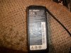
problem is more the 16V output of the PS... you may want to regulate or drop it to probably 14.7 volt?? am not sure on that voltage. how much is needed to keep that battery charged?
Nothing stop it from overcharging/overvoltage ruining the battery at 16volt?,
I guess someone could use some serie diode to create a voltage drop(to about 14.7Volt??) or ALOT better a zener diode and use a power transistor so you don't have to source a high wattage diode and resistor and it vill be voltage regulated and can easilly include current sensing/protection. Thats a big change in the design, but can be done with very little component.
Another way is using a voltage regulator and power transistor. so its at the correct voltage(whatever the input voltage is), and the current is also regulated.
Much more simple, part are harder to source when building from scratch. But at this point, probably less hassle to buy one..
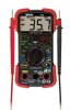
EDIT: if you want to measure the maximum output current of your PS,
Just use a big wattage low value resistor between + and - and measure the voltage drop accross it and use the ohm law.
But be carefull, it should have a short circuit protection/over current.. but maby not, so you dont want to ruin it.
Measuring the maximum output current will probably prove to be useless since you want to design a circuit that will not overload the 4.5amp limit of your PS in all case anyway.