Tuning With An Air/Fuel Logger

2Loose

reliable source of info
Tuning A Blown Olds Motor w/ Dual Mighty Demons with an Innovate LM-2 Air/Fuel Logger....

My latest project is an old style 60's era '55 Chevy "gasser" project. Complete with an early Ford F1 truck front axle, a stick shift, a stiff clutch, a built up '67 Olds 425 motor, a 6/71 blower, a heavy duty Ford 9" rear end with a Detroit Locker, and a pair of Mighty Demon 650's.

I built up the 425 Olds motor specifically for a stick shift blown street/strip operation with a 6/71 and dual carbs. Found a used pair of Mighty Demon 650's set up for a roots blower with remote vacuum sensors for the power valves.

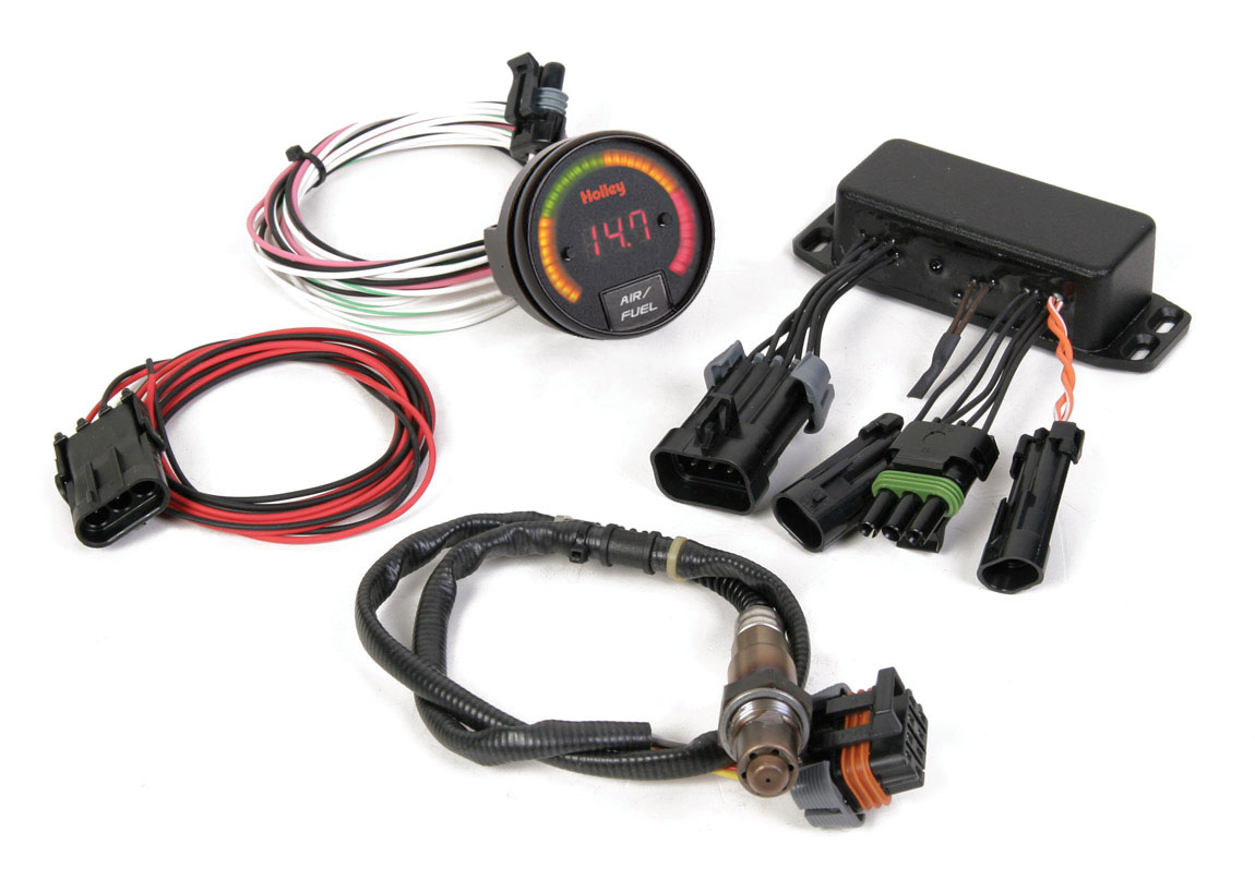
My old LM-1 A/F logger went up in smoke before I could get it on this motor for tuning, so sent it in for an upgrade to the LM-2. Using basic tuning techniques I got it running pretty good, but I want to do a better job. Just got my new LM-2 yesterday, got the software in the laptop, and am ready to do some logging and see just where I am at.

Thought I might run a thread here on what I find and how I adjust it. Anybody wants to tune in with comments, you're more than welcome, as I trip on through this learning event....

At this point the 8:1 pistons and 1:1 blower drive are pulling 15 inches at idle, 900-1000 rpm, and giving me 5 lbs at full boost. I'm running progressive linkage on the secondaries. 72/75 primary/secondary jets. #4 power valves primary only. Idle fuel screws at 3/4 out. Don't know and have not addressed what accel pump cams or squirters are in there yet.

Messed with the timing quite a bit. Using an MSD 6AL with the blower timing retard add-on, and the dash timing control add-on. We found out fairly quickly that this motor seems to like a fair amount of advance in the ignition timing. I'm using heavy springs on the mech. advance with 20 deg advance available, coming in all the way fairly late, about 3000 rpm. Initial setting at idle with no vacuum advance is 18, giving a total of 38 deg at 3000. I am using the vacuum advance at idle, it is 10 deg, so giving 28 at idle, which the motor seems to like. So from idle at 28, it backs off to 18, then advances to 38 full advance at 3000, as long as I am not into boost. Driving it on the street it very seldom gets into boost, is making so much power without the boost that I just never get that far into it on the street.

When going into boost I get detonation, so added 2 deg of retard per lb of boost, making the 5 lb full boost timing at 3000 backed off 10 deg to 28 deg. Not sure that is the best setting for now, but the plugs look pretty good, kind of a dark cola brown, and the exhaust pipe is a light gray color, and I don't think I can hear any detonation. I'm not sure how well adding a detonation sensor would work, as I have heard that the roots blower noise tends to mask that and can give false information.

As I mentioned above, I do have the adjustable timing control mounted on the dash. I have it set at 10 on the dash with the 38 full in at 3000. I have the option to advance timing up to an additional six, or to retard it, up to a max of ten. So far I have only advanced or retarded it a couple of degrees while driving but haven't been able to see much difference. So for now I just leave it at 10, which is the 38 setting on the distributor. I hope that all made sense!

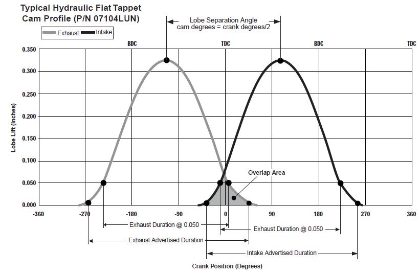
At 1/2 turn out on idle screws it idled more smoothly, but when driving would die off when taking my foot off the gas and hitting the clutch at stop signs. Upping the idle screws to 3/4 turn stopped that, but now it can occasionally get into a surging idle condition that can build until it goes so far down at idle on the low end of the surging that it dies off. I feel I ought to be able to tune out that "typical blower surging" that so many people think is normal for a roots blown motor. It's what I consider a slightly aggressive street cam, hydraulic roller lifters, but fairly tame really when I look at the specs (230/236 duration at .050, .507/.516 lift, with fairly steep ramps due to the roller lifters).

Part of that die off problem is the really light (12 lbs) aluminum flywheel I put in. It revs up and drops back down really, really quickly when I hit the throttle. It's like the carbs can't "catch" it fast enough to recover when it comes back down from a throttle jab, and it slows down too much and dies.

On startup it hits on the first fire, instantaneously, hot or cold.

Am down with a bad cold today, so had time to do research on the LM-2 and carb tuning, and thought I'd post this thread. As I get some logs will post what I find.
Aloha from Maui,
2Loose Willy

viewtopic.php?f=50&t=9250&p=33361#p33361

LINK: If you are interested, I have been running some build pages on this project.
 
Since I posted that first bit, I've been driving it on the street quite a bit, readjusted the dash control to 8 deg, making the idle at 16 base, plus 10 vac. adv. to 26 idle, still getting 15 to 17 inches vac. at idle, and mech. adv. of 20 to 36 total now, all in at about 3500, and minus ten at full 5 psi boost to 26 deg. at full boost. Seems to be running pretty good.

Took it to the track, passed tech. inspection with the "new" '48 ford truck front axle (not cut, not welded, like the first one, a '59 F100 axle they objected to....), on my first test and tune run, had a little trouble getting the line lock to come on, didn't break the beam, but was slow getting off the line, and damn near bogged it trying for a softer start in 2nd gear, hit only 3rd and 4th, rode the stutter box through the lights, outcome was 110 at 15 seconds. My thought? OK, there's an easy 125 at 10.xx seconds in this car when I finally get a clean start and shift to fifth. The car ran straight and clean, an easy drive. Low gear in this DN 4+1 is 3.28, with the 3.50 rear that is 11.48 overall, pretty deep gears, so on my second t&t run thought I'd just see how well it would hook using low gear.

The line lock worked well on the second approach, smoked the tires very well in the wet box, got smoke inside the car for the first time, gonna hafta check out where that's gettin in, dry hopped it to the line and staged, popped the clutch at about 3000 and brought up the front end pretty well, 2+ ft maybe with the blower building boost and tore off the front u-joint!!! :roll:

I have a Strange Engineering chrome moly driveshaft in there with 1350 u-joint/yokes in the rear, but had a 1350 by 1330 cross in the front with a stock th400 yoke in the tranny, I tore off the 1330 sides on the cross and one of the ears on the th400 tranny yoke! Am rebuilding it now with 1350 yokes and cross on the front end of the driveshaft.

Rear end is a Currie 9+ 35 spline setup I got from a drag racer on Oahu, as the track there is shut down, lot of stuff for sale cheap on Oahu. Tires are 12" wide (tread) BF Goodrich G-Force T/A Drag Radials, 325/50R15's, on 12" rims, DOT legal, drive 'em to the track, ran 'em at 20 lbs and they hooked up real good!!! :mrgreen: :mrgreen:

Ladder bars, panhard bar, QA-1's set max stiffness, the setup seemed to work very well, at least I know I am making power and it is hooking!

With the car towed back to the shop and up on jackstands, finally got the A/F logger to work, there were a few demons in both the software and the hardware that I had to chase and cure before I finally got it to log and to read the log on the laptop. Idle and rev-ups are still pretty fat, 10.5 to 11 at idle, want to get it up to 14's for idle and cruise, and fatten it up a little to high 13's as I bring the primary jets into action. Mid 13's for pv add-in and secondarys. That's my goal for tuning.

Once I get the parts and repair the driveshaft, I will take it out on the road and log some events and see how it looks, then start to do some real fine tuning. First goal is to get the idle/cruise circuits into the low 14's with all 8 idle screws somewhere between 2 and 3 turns out, now they are turned in so tight it is a very delicate tune between 1/2 and 3/4 turns out, my opinion is the idle circuit air and fuel bleeds need some work to cure this.

Here's some good reads for tuning carbs with an A/F logger:
http://www.innovatemotorsports.com/reso ... ileage.php
http://www.innovatemotorsports.com/reso ... g-hero.php
http://www.innovatemotorsports.com/resources/Stan1.php

Here's a quote at the Innovate Motorsports website that inspired me:
"A carbureted engine can produce just as much horsepower as a fuel-injected engine. The trick is tuning. Probably the main advantage of fuel injection is its "tune-ability." With an LM-1 air/fuel ratio meter, and a little knowledge, any carburetor is tuneable."

Other links are here at the Innovate site:
http://www.innovatemotorsports.com/reso ... entral.php

Anyone else who has tuned carbs with an A/F logger like the Innovate unit, please add your experiences here, I think this is valuable information, and I have found very little of it on the internet.

Much Aloha to all....
Willy
 
FUEL METERING
http://www.max-boost.co.uk/max-boost/in ... tering.htm

http://www.holley.com/TechService/Libra ... lInjection

http://www.innovatemotorsports.com/products/MTS.php

THE COMBUSTION PROCESS BURNS A MIXTURE OF AIR AND FUEL. THIS AIR AND FUEL MIXTURE IS REFERRED TO AS THE A/F RATIO. AS THE RELATIVE AMOUNT OF FUEL IN THE MIXTURE DECREASES ( A LEANER MIXTURE ) THE A/F RATIO VALUE BECOMES LARGER. AS THE PROPORTION OF FUEL BECOMES GREATER ( A RICHER MIXTURE ) THE A/F RATIO VALUE BECOMES SMALLER.

THE A/F RATIO OF AN ENGINE MAY BE MEASURED IN MANY WAYS, BUT THE MOST REPRESENTATIVE AND ACCURATE METHODS USE HIGHLY SPECIALIZED EXHAUST GAS ANALYZERS. THE A/F RATIO INFORMATION IS THE KEY TO ESTABLISHING AN APPROPRIATE FUEL METERING CALIBRATION FOR A GIVEN ENGINE COMBUSTION. ANYONE ATTEMPTING TO OPTIMIZE AN ENGINE A/F RATIO SHOULD PURCHASE AND UTILIZE AN A/F RATIO MIXTURE METER. WHETHER YOU ARE TUNING A CARBURETOR, FUEL INJECTION OR FORCED INDUCTION AND USING UNLEADED FUEL, THERE ARE MANY TO CHOOSE FROM, THE "WIDE BAND" VERSION IS THE PREFERRED VERSION. DO NOT DISCOUNT THE "NARROW BAND" VERSION, EITHER VERSION IS FAR MORE ACCURATE THAN "I THINK IT'S LEAN" OR "IT FEELS RICH", WITHOUT ACCURATE INFORMATION YOU ARE WASTING TIME, MONEY AND POSSIBLY THE ENGINE.

A FULLY WARMED UP ENGINE WITH AN A/F RATIO AS RICH AS 6.0-1 AND AS LEAN AS 22.0-1, THESE ARE THE GENERAL RICH AND LEAN COMBUSTION LIMITS, BUT DURING ACTUAL DRIVING SITUATIONS THE ACTUAL A/F RATIO NEEDED DURING VARIOUS OPERATING CONDITIONS WILL BE VERY CLOSE TO THE MID-POINT OF THESE EXTREMES.

A/F RATIO COMMENT
bullet

9.0:1 BLACK SMOKE (NO POWER)
bullet

11.5:1 RICH BEST TORQUE @ WOT
bullet

12.2:1 SAFE BEST POWER @ WOT
bullet

13.3:1 LEAN BEST TORQUE @ WOT
bullet

14.6:1 STOCHIMETRIC AFR ( CHEMICALLY CORRECT )
bullet

15.5:1 LEAN CRUISE
bullet

16.5:1 BEST FUEL ECONOMY (EXCEPT FOR HONDA MOTOR COMPANY)
bullet

18.0:1 CARBURETED LEAN LIMIT (EXCEPT FOR HONDA MOTOR COMPANY)
bullet

22.0:1 EFI LEAN LIMIT

GENERALLY ENGINES OF DIFFERENT BASIC DESIGNS HAVE THE SAME A/F RATIO REQUIREMENTS. THESE CALIBRATION NEEDS ARE TYPICALLY A FUNCTION OF OPERATION MODE, ENGINE TEMPERATURE, ENGINE SPEED, AND LOAD. GENERALLY A PRODUCTION BASED HIGH PERFORMANCE ENGINE WILL HAVE A/F RATIO VALUES IN A RANGE FROM 12.0:1 TO 16.0:1.

COLD ENGINE

THE COMBUSTION PROCESS REQUIRES VAPORIZED FUEL. MOST OF THE VAPORIZATION OCCURS AFTER THE AIR AND FUEL DROPLETS HAVE MOVED PAST THE INTAKE VALVE, BUT A LARGE PORTION MUST OCCUR BEFORE THE INTAKE VALVE OPEN. IN A COLD ENGINE THE AIR, FUEL AND ALL THE COMPONENTS CONTACTED BY THE FUEL ARE AT TEMPERATURES THAT DO NOT PROMOTE VAPORIZATION, SO ADDITIONAL FUEL MUST BE ADDED SO THAT THE PERCENTAGE THAT DOES VAPORIZE WILL SUPPORT COMBUSTION. THE AMOUNT OF THIS ADDITIONAL FUEL (COLD ENRICHMENT) DEPENDS ON THE TEMPERATURE. IF THE STARTING CLIMATE IS VERY COLD (-20F) THE A/F RATIO MAY NEED TO BE 4.0:1, AS THE ENGINE WARMS UP, THE A/F RATIO MUST BE LEANED TO NORMAL VALUES.

IDLE

THE A/F RATIO FOR A STABLE IDLE IS DETERMINED PRIMARILY BY THE CAMSHAFT PROFILE. A LONG DURATION CAMSHAFT WITH BIG VALVE OVERLAP CAUSES THE INLET CHARGE TO BECOME DILUTED BY EXHAUST GASES, THIS DILUTED CHARGE BURNS VERY SLOWLY AND MAY REQUIRE A LOT OF SPARK ADVANCE. ALSO THE COMBUSTION BECOMES ERRATIC, SO A RICH A/F RATIO IS REQUIRED TO REDUCE THE CYCLIC VARIATION (LOPING IDLE) WHEN TUNING. THE A/F RATIO MAY NEED TO BE 11.5:1 OR RICHER WITH A REALLY SERIOUS RACE CAMSHAFT PROFILE. WITH A SHORT DURATION CAMSHAFT PROFILE THE A/F RATIO DOES NOT NEED TO BE AS RICH FOR A STABLE IDLE AND MAY BE AS LEAN AS 14.7:1 WHERE EMISSIONS NEED TO BE A MINIMUM.

LOW SPEED AND LIGHT THROTTLE

THE CONDITIONS THAT AFFECT A/F RATIOS AT IDLE ALSO AFFECT THE FUEL CALIBRATIONS AT OFF-IDLE OPERATING CONDITIONS WHERE ENGINE RPM IS LOW AND THE LOAD IS LIGHT (LOW INLET DENSITY AND HIGH MANIFOLD VACUUM). AGAIN THE LONGER VALVE DURATION / OVERLAP, THE RICHER THE A/F RATIO WILL NEED TO BE FOR SURGE-FREE OPERATION. IN THE IMMEDIATE OFF-IDLE RANGE THE A/F RATIO MAY NEED TO BE AS RICH AS THE IDLE, SOMEWHERE AROUND 12.5:1 TO 13.0:1 IS COMMON, THEN GRADUALLY BECOMING LEANER WITH AN INCREASE IN SPEED OR LOAD. WITH A VERY MILD CAMSHAFT PROFILE, THE ENGINE MAY TOLERATE A/F RATIOS IN THE 14.0 TO 15.0:1 RANGE FOR THE SAME OPERATING CONDITIONS.

MINIMUM SPEEDS AND LOADS

AS ENGINE RPM INCREASES THE THROTTLE IS OPENED, THE EFFECT VALVE DURATION AND OVERLAP BEGIN TO DIMINISH. THERE IS LESS INLET CHARGE DILUTION, SO A LEANER A/F RATIO MAY BE USED WITHOUT ANY SURGES OR DRIVABILITY PROBLEMS. A/F RATIOS FROM 14.0 TO 15.5:1 ARE THE NORM. TYPICALLY THE BEST ECONOMY A/F RATIO IS FROM 15.5 TO 16.5 WITH A "STREETABLE" HIGH PERFORMANCE ENGINE COMBINATION, BUT WILL REQUIRE ADDITIONAL SPARK ADVANCE TO COMPENSATE FOR THE SLOW BURN RATES OF LEAN MIXTURES.

HEAVY LOAD AT PART THROTTLE

AS LOAD ON THE ENGINE INCREASES FROM ADDING MORE THROTTLE OPENING (HIGH INLET CHARGE DENSITY / LOW MANIFOLD VACUUM) THE A/F RATIO NEEDS TO BE ENRICHED TO PRODUCE MORE POWER AND REDUCE THE DRIVABILITY ISSUES BECAUSE OF LEAN A/F RATIOS AT HIGH LOADS. THE A/F RATIO SHOULD BE SOMEWHERE BETWEEN THE CRUISE AND WOT A/F RATIO VALUES, GENERALLY AROUND 14.5 TO 13.0:1 DEPENDING ON LOAD AND SPEED.

WIDE OPEN THROTTLE

ALL 4-CYLE GASOLINE ENGINES HAVE AROUND THE SAME A/F RATIO NEEDS AT WOT, WHERE THE GOAL IS TO PRODUCE THE MAXIMUM TORQUE / POWER FROM A GIVEN ENGINE COMBINATION. THE LEANEST A/F RATION THAT PRODUCES MAXIMUM TORQUE / POWER IS REFERRED TO AS "LEAN BEST TORQUE" WHICH IS USUALLY AROUND 13.3:1 A/F RATIO. THE RICHEST IS A A/F RATIO OF 11.5:1 "RICH BEST TORQUE". THE DIFFERENCE BETWEEN "LEAN BEST TORQUE" AND "RICH BEST TORQUE" CAN BE CLOSER AT HIGH ENGINE SPEEDS, SO THE BEST TARGET A/F RATIO FOR WOT USAGE IS BETWEEN 12.0 TO 12.5:1 A/F RATIO, THIS INSURES THE BEST PERFORMANCE AT WOT POWER UNDER ALL CIRCUMSTANCES.

SPARK ADVANCE REQUIREMENTS

THE CHARGE OF THE AIR / FUEL IS BURNED BY A FLAME-FRONT BEGINNING AT THE SPARK PLUG. THE FLAME STARTS A KERNEL WITH A RATHER SLOW RATE OF EXPANSION, BUT ONCE A SMALL PERCENTAGE OF THE CHARGE IS IGNITED, THE COMBUSTION PROCESS ACCELERATES AT A FASTER RATE. DUE TO THE VERY SLOW INITIAL REACTION RATES, IGNITION MUST OCCUR "BEFORE TOP DEAD CENTER" IF MAXIMUM EFFECT IS TO BE UTILIZED. THIS IS THE "ADVANCE" IN IGNITION AND IS MEASURED IN DEGREES OF CRANKSHAFT ROTATION. THE BEST ADVANCE USUALLY PRODUCES THE BEST TORQUE WHEN MAXIMUM CYLINDER PRESSURE IS ACHIEVED AT AROUND 15 DEGREES "AFTER TOP DEAD CENTER". DEPENDING ON DESIGN AND OPERATING CONDITIONS, THE SPARK ADVANCE CAN BE FROM LESS THAN 5 DEGREES UP TO MORE THAN 30 DEGREES FOR A HIGH PERFORMANCE / RACE ENGINE, AND 0 DEGREES UP TO MORE THAN 50 DEGREES FOR A STOCK PRODUCTION ENGINE WITH EMISSION COMPONENTS IN PLACE AND FUNCTIONAL.

THOSE OF US IN ENGINE DEVELOPMENT STRIVE TO CALIBRATE SPARK ADVANCE TO VALUES REFERRED TO AS " MINIMUM BEST TORQUE", THIS IS THE MINIMUM SPARK ADVANCE THAT WILL PRODUCE THE MAXIMUM TORQUE AT A GIVEN OPERATING CONDITION OF SPEED AND LOAD OF A GIVEN ENGINE COMBINATION. IN MOST CASES THE SPARK ADVANCE CURVE CAN BE ADVANCED SEVERAL ADDITIONAL DEGREES BEYOND "MINIMUM BEST TORQUE" BEFORE TORQUE BEGINS TO DROP OFF. IF "KNOCK" OCCURS BEFORE "MINIMUM BEST TORQUE" ADVANCE CAN BE DETERMINED. THE ADVANCE IS REFERRED TO AS "KNOCK" LIMITED. THE FUEL OCTANE, CAMSHAFT PROFILE AND OR THE ENGINE'S STATIC COMPRESSION RATIO WILL NEED TO BE ADDRESSED BEFORE MAXIMUM OUT-PUT CAN BE ACHIEVED.

THE VARIABLES THAT INFLUENCE THE SPARK ADVANCE REQUIREMENT INCLUDE THE BASE ENGINE DESIGN, THE SPECIFIC COMPONENTS OF THE PARTICULAR ENGINE ( CAMSHAFT, COMPRESSION, PISTON AND CYLINDER HEAD CONFIGURATION), THE INTENDED FUEL TO BE USED AND THE OPERATING CONDITIONS (RPM / LOAD / TEMPERATURES). THE SPARK ADVANCE GENERALLY INCREASES WITH ENGINE RPM UP TO A POINT WHERE IT WILL "PEAK" AND IN SOME CASES WILL DECREASE SLIGHTLY WITH FURTHER INCREASE OF RPM. ADVANCE REQUIREMENTS DECREASES WITH LOAD AND THE MINIMUM ADVANCE AT ANY GIVEN ENGINE SPEED IS AT WOT.

THE ADVANCE REQUIREMENTS OF AN ENGINE OF THE SAME DESIGN BUT DIFFERENT COMPONENTS ARE DICTATED MORE BY CAMSHAFT PROFILE, INCLUDING COMPRESSION. WITH A RADICAL CAMSHAFT PROFILE, THE WOT ADVANCE CURVE CAN BE VERY AGGRESSIVE AND REACH MAXIMUM ADVANCE AT A LOWER RPM BECAUSE OF THE POOR VOLUMETRIC EFFICIENCY AT LOW RPM, AND A VERY SLOW COMBUSTION RATE AND ITS HIGH RESISTANCE TO "KNOCK". PART THROTTLE ADVANCE ON ENGINES WITH LARGE CAMS CAN ALSO BE AGGRESSIVE BECAUSE OF THE REDUCED FLAME SPEED CAUSED FROM A SIGNIFICANT EXHAUST DILUTION OF THE INLET CHARGE FROM A CAMSHAFT WITH A LOT OF OVERLAP.
 
holleytunekit.jpg

HOLLEYS GOT A NEW TOY
Want to closely monitor Air/Fuel ratios on your carbureted or EFI vehicle? Holley has just the product for you. Holley is proud to introduce the Holley Wide Band O2 Controller with gauge.

http://www.summitracing.com/parts/fst-1 ... dia/images

A wide band oxygen sensor is the ultimate addition to any carbureted or EFI vehicle. It will accurately measure any air/fuel ratio between 10:1 and 18:1. This allows the engine tuner to read the air/fuel ratio in real time for extremely accurate tuning.

The 534–201 kit is intended for the consumer who wants to be able to accurately measure air/fuel ratios so the perfect tune up can be obtained. The 534–201 can also be upgraded later for use with an NTK sensor by simply reconnecting a jumper loop and purchasing the NTK sensor (P/N 534–194).

The Holley Wide Band O2 gauge features a 3–digit numeric display along with a 40 segment bar graph. With the ultra–high intensity light emitting diodes you will be able to see your Air/Fuel ratio even under direct sunlight.

The P/N 534–201 is designed to operate in street or race environments and will withstand heat, dirt, and vibration. The Holley Wide Band O2 gauge will fit in a standard 2–1/16” gauge pod.


Features

Controller Features: Small weather-sealed unit for convenient mounting
Easy Installation
Accurately measures A/F ratio between 10:1 and 18:1
Will accommodate a Bosch or NTK sensor
Includes Bosch LSU4 Sensor
Aides in tuning for maximum power and fuel economy
Gauge Features: Features a 3-digit numeric display and 40 segment multicolor bar graph for a quick read
Ultra-high intensity light emitting diodes for easy viewing even in direct sunlight
Standard 2-1/16” diameter for ease of mounting in a standard gauge pod
Built for race environments to withstand heat, dirt, and vibration
Connects to vehicle light switch to dim the gauge during night time viewing


Technical Information
Instructions for Part# 534-201

Shipping Dimensions
L 7.750 in. x W 5.250 in. x H 3.250 in.
Weight 2.000 lb.

one factor I seldom seen mentioned is the fact that fuel must be atomized and mixed with air in a vapor form to burn effectively, and that oxygen sensors measure the remaining un-used oxygen in the exhaust gases, NOT the REMAINING FUEL CONTENT and the difference is important as your tail pipe could be dripping raw fuel while the oxygen sensor reads a LEAN REMAINING HIGH OXYGEN CONTENT in the exhaust gases, being measured by the oxygen sensor data, if the fuel was poorly atomized and far less that 100% of the fuel flow passing thru the cylinders is being burnt efficiently.
a highly effective exhaust header scavenging the cylinder matched to a cam with significant over lap can quite easily promote that result if the fuel is not being efficiently atomized, especially in a fairly cool combustion chamber.

4cyl1a.jpg


4cyl2.jpg

4cyl3.jpg

engbal5.gif

exhaustpressure.jpg


EXFLOWZ4.jpg

Stoich.gif

o2grph.gif


AFR_Torque.gif

volumetric.gif

GLOWING RED HEADERS

http://www.hotrod.com/articles/innovate-air-fuel-ratio-meter/


GLOWING RED HEADERS

think it through ...thats USUALLY the result of a good deal more HEAT exiting the engine in the form of HOT exhaust gasses,exiting the cylinder and entering the headers..
hot exhaust gasses result from either overly lean fuel/air ratios
OR
a retarded ignition timing, that delays the burn of the compressed gases, and allows still burning fuel /air mix to exit the exhaust port.
OR
cam timing that is causing very effective cylinder scavenging that allows some of the fuel/air mix to enter the headers after passing through the cylinder , as inertia drags it out following the previous exhaust gases ,before the exhaust valve closes.
OR
very rarely miss firing injectors throwing excessive fuel
honestly a bit of basic engineering and thinking about a cause and effect relationship and a bit of testing can go a long way toward isolating a logical search for any problem.
it should also be obvious that as the rpms increase so does the volume of exhaust gases and thus the heat transferred to the exhaust, at idle your more than likely seeing less than 500 pulses of hot exhaust entering the headers per minute , at 6000 rpm thats 3000 pulses of hot exhaust entering the headers per minute

pistonposition2.jpg

cycl51.png


0900c.gif

Re: C4 sensor info

you really need a old computer, an ADL cable and software to read the info and of course YOU NEED a shop manual for YOUR YEAR CORVETTE, and a MULTI METER
reading links may seem like a waste of time , but having a shop manual, a decent up-to-date, scan tool and a multi meter and a good understanding of what your testing and why your testing it helps a great deal
like the old saying how do you eat an elephant ?......one little bite at a time! :D

all the answers are readily available, theres known testing procedures and listed test results you can expect, and procedures listed in the shop manual for isolating and testing components, you don,t need to be a genius, you just need to be logical and persistent and not afraid to learn new things while getting your hands dirty at times, don,t get overwhelmed , break everything down too easy individual problems and tests, verify and test all the sensors,and test for factors like consistent fuel pressure, known temps,expected voltage or ohms resistance, and vacuum readings and don,t randomly start replacing parts as that gets expensive and its rarely the most efficient way to eliminate problems(unless you get really lucky) with modern computer diagnostic software you,ll have some advantages but think logically, most automotive problems still concern, loose electrical connectors, defective sensors, lack of compression, fuel delivery issues ,fuel pressure, vacuum, temperature or electrical issues.


http://www.helminc.com/helm

1996_Corvette.jpg

image_6238.jpg


Measured Value
Engine Coolant Temperature Sensor. 185 Ohms @ 210F, 3400 Ohms @ 68F, 7,500 Ohms @ 39 F.
Engine Oil Temperature Sensor. 185 Ohms @ 210 F, 3400 Ohms @ 68 F, 7,500 Ohms @39 F.
Oil Pressure Sender/Switch. 1 Ohms @ 0 PSI, 43 Ohms @ 30 PSI, 86 Ohms @ 60 PSI.
Fuel Quantity Sender. 0 Ohms @ Empty, 45 Ohms @ 1/2 Full, 90 Ohms @ Full.
MAT (Manifold Absolute Temperature Sensor). 185 Ohms @ 210 F, 3400 Ohms @ 70 F, 15,000 Ohms @ 40 F.
Outside Temperature Sensor. 4400 Ohms @ 60 F, 2200 Ohms @ 85 F.
In Car Temp Temperature Sensor. 4400 Ohms @ 60 F, 2200 Ohms @ 85 F.
MAF (Mass Air Flow) Sensor. .4 Volts @ idle, 5 Volts @ Full Throttle.
Oxygen (O2) Sensor. .1 Volt Lean Mixture, .9 Volt Rich Mixture.
TPS (Throttle Position Sensor). .54 Volts Idle, ~ 5 Volts Full Throttle.

Sensor Locations

Sensor


Location
Engine Coolant Temperature Sensor. Front of engine, below Throttle Body.
Engine Oil Temperature Sensor. Left rear of engine, just above the oil filter.
Oil Pressure Sender/Switch. Top, left hand rear of engine.
Fuel Quantity Sender. Top of fuel tank, beneath filler pipe escutcheon panel.
MAT (Manifold Absolute Temperature Sensor). Underside of manifold air plenum at rear.
Outside Temperature Sensor. Right side of engine, top right corner of radiator.
In Car Temp Temperature Sensor. Coupe: above left seat near interior courtesy light, Convertible: center of cargo compartment lid.
MAF (Mass Air Flow) Sensor. Front of engine ahead of throttle body.
Oxygen (O2) Sensor. Left side of engine, in exhaust pipe.
TPS (Throttle Position Sensor). Right side of throttle body at the front.


http://garage.grumpysperformance.co...lay-switch-locations-and-info.728/#post-54562

http://garage.grumpysperformance.com/index.php?threads/odbii-scanners.9697/#post-36100

http://garage.grumpysperformance.com/index.php?threads/code-scanners-software.3096/#post-18612
 
Last edited by a moderator:
Back
Top