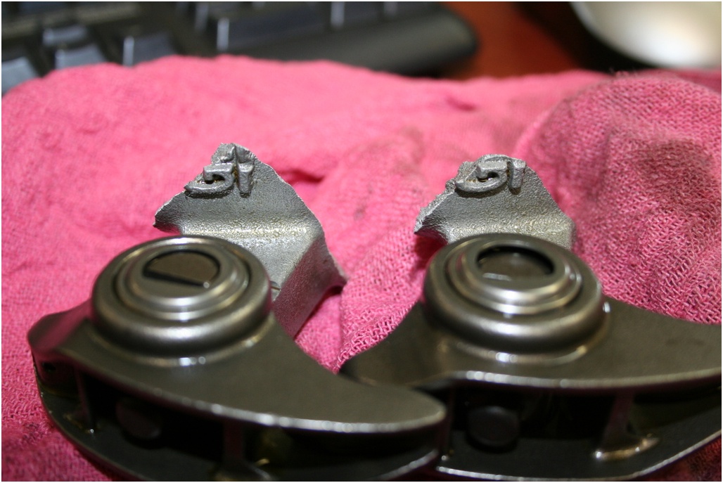
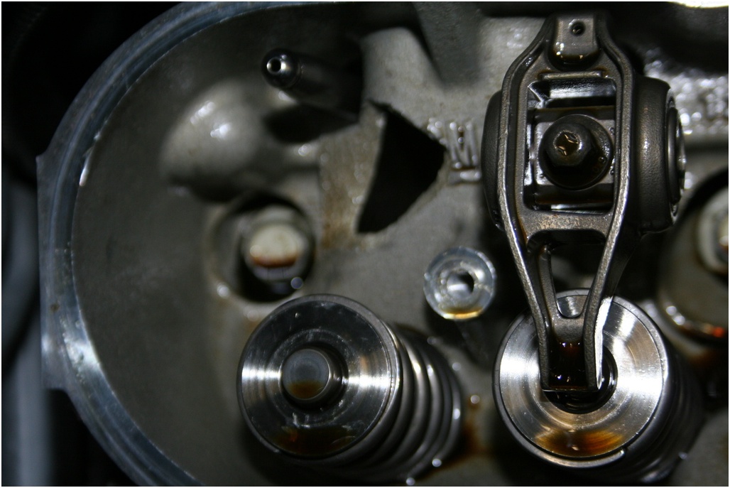
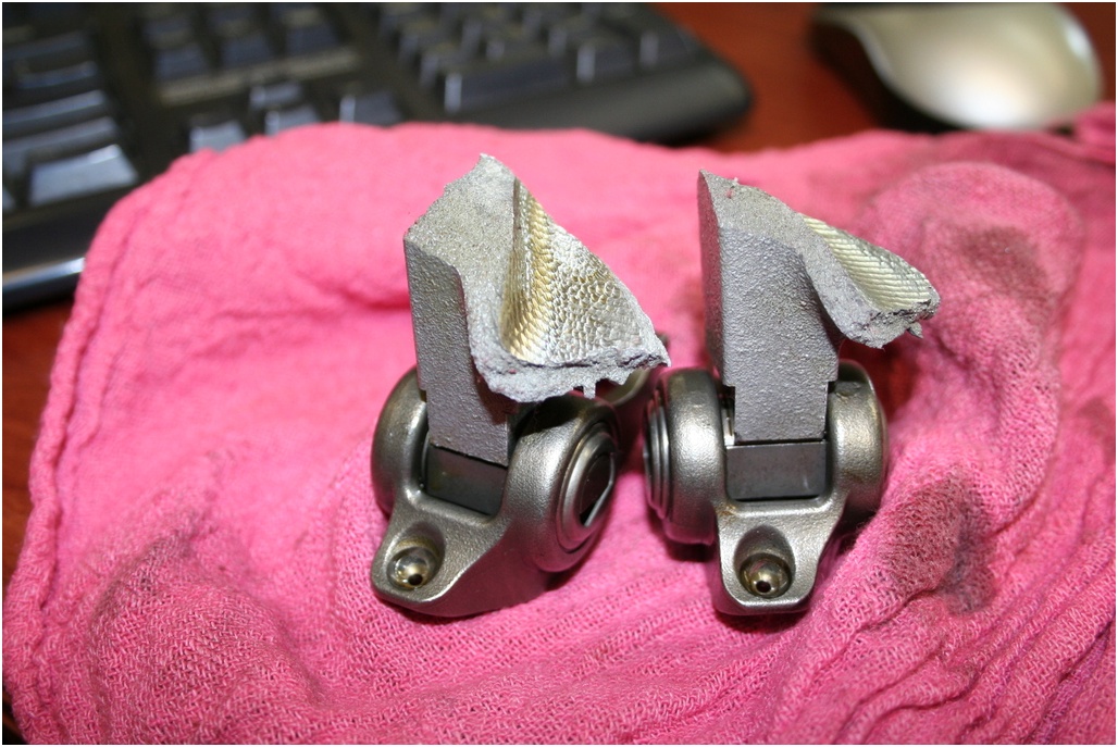
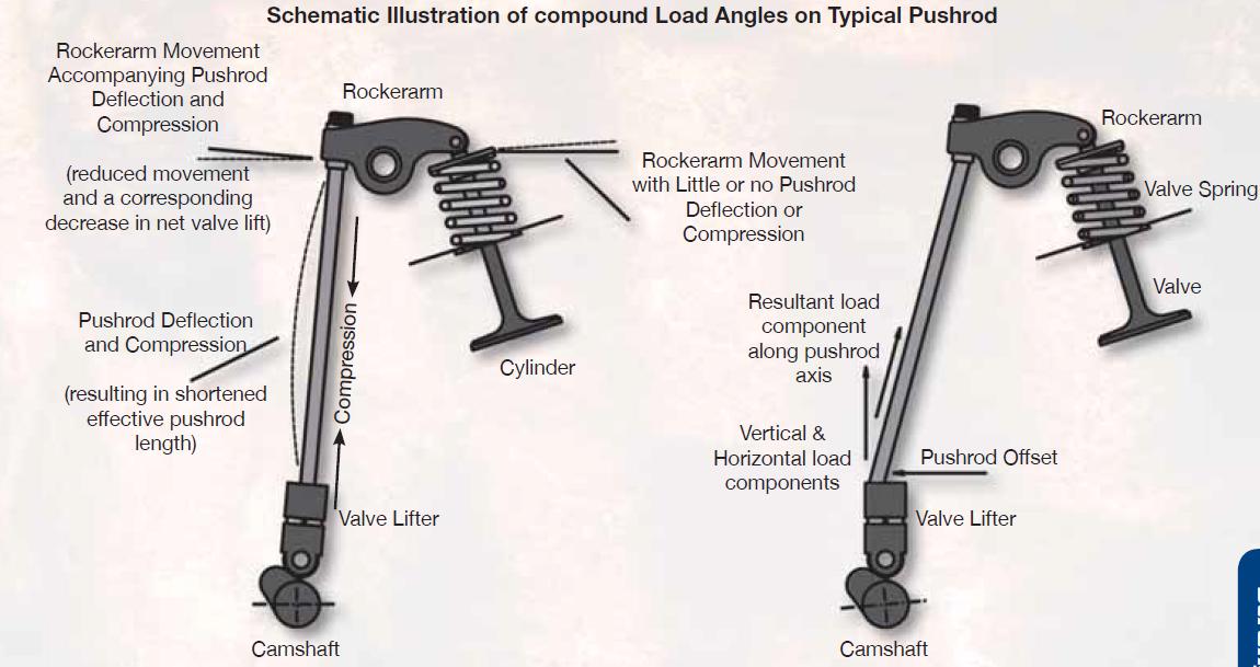
KEEP in mind the main idea here is to keep BOTH the rocker arm pushing strait down the center line of the valve to minimize friction and valve guide wear,and to keep the pushrod length at the correct dimension to minimize friction and match the intended angle of operation designed into the valve train, and to do that the basic geometry and clearances, and geometry in that valve train must be correct...you may need too use the correct adjustable guide plates when you find the push-rod alignment is in need of minor tweaking to get the clearance and geometry correct,
don,t forget as many guys do, that swapping to a higher ratio rocker changes the push-rod rocker geometry,and clearances, the heads and rockers used obviously effect the required clearance, but you'll usually want at least 60 thousands clearance on the push rods to slot measurements and you'll want to rotate the engine thru two complete revolutions while verifying that clearance, while watching the push-rod geometry as it changes as the rockers move thru their arcs and may require a different length push-rods.
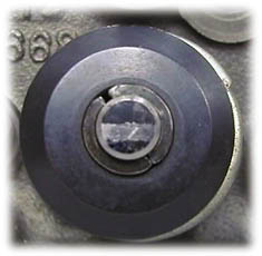
Pushrod Too Long: Notice how the pattern is wide, and shifted to the exhaust side of the valve tip.

Pushrod Too Short: Notice how the pattern is wide, and shifted to the intake side of the valve tip.
Pushrod Length Correct: Notice how the pattern is narrow and is centered on the valve tip.
if your rocker geometry, does not appear to be correct ,start at the basics
http://www.summitracing.com/parts/PRO-66789/
http://www.summitracing.com/parts/TFS-9001/
verify your correct geometry first
http://www.thedirtforum.com/pushrodlengths.htm
http://www.compcams.com/catalog/278.html
http://www.carcraft.com/techarticles/11 ... index.html
heres useful links and info below
http://www.compcams.com/information/Products/Pushrods/
http://www.trendperform.com/
http://www.popularhotrodding.com/engine ... ables.html
http://www.mantonpushrods.com/
http://www.aa1car.com/library/2004/eb30431.htm
http://www.cranecams.com/?show=technicalhelp
http://www.circletrack.com/techarticles ... index.html
http://www.compcams.com/Technical/FAQ/V ... ometry.asp
http://www.grapeaperacing.com/GrapeApeR ... etrain.pdf
YOULL NEED TO CAREFULLY CHECK YOUR PARTICULAR ENGINE!
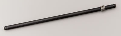
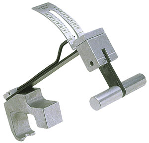
heres a simple way to get close to the correct length
BUY ONE OF THESE
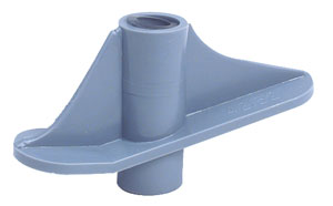

http://www.jegs.com/cgi-bin/ncommerce3/ProductDisplay?prrfnbr=3567&prmenbr=361
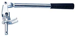
after making sure the valve springs are correctly installed you drop the checker in place on the rocker stud and install your adjustable pushrod
adjust the length to fit and measure the resulting length if its within twenty thousands of the stock length its fine for most applications, if its more than 30 thousands long or short get the closest length set available
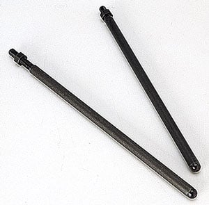
<b>btw, if your one of the people that still does not own an adjustable push rod! you can easily make your own by cutting a stock pushrod in 1/2 (2 pieces), removing 1 inch from the total length an then with about 2 " of a 4 inch section of 3/16 or 1/4" thread rod installed and (in one section epoxy it in place leaving about 2" sticking out thread two nuts onto the thread rod and slip on the other end of the cut pushrod,(no epoxy) use the two nuts to adjust to stock length and let the epoxy hardened in the one section[/color] now you can easily measure and order custom push rods useing the pushrod checker and adjustable push rod as tools
AND YEAH IT ONLY WORKS WITH THE CYLINDER HEADS ON AND THE INTAKE REMOVED BECAUSE THE HOLE IN THE CYLINDER HEAD that GUIDEs THE PUSH ROD WON,T ALLOW THE NUTS ON THE ADJUSTABLE PUSHROD TO PASS THRU, UNLESS YOU PLACE THE CUT ABOUT 1" from the UPPER END OF THE ADJUSTABLE TEST PUSHROD BUT I prefer to place the adjusting nuts centered as I like to watch for all clearances with the intake manifold removed while manually checking as I turn the engine over by hand durring assembly, and at that point, while checking all the clearances, I use test springs which apply very little load on the push rod</b>

http://www.jegs.com/cgi-bin/ncommerce3/ProductDisplay?prrfnbr=3272&prmenbr=361
HERES OTHER TOOLS YOU MIGHT NEED
SOMETHING TO READ
http://www.compcams.com/information/Products/Pushrods/
CCA-7705 5.800 in. to 9.800 in. adjustment range, Master pushrod length checker 4 piece kit ... $78.69
http://store.summitracing.com/egnsearch ... &x=36&y=11
don,t forget as many guys do, that swapping to a higher ratio rocker changes the push-rod rocker geometry,and clearances, the heads and rockers used obviously effect the required clearance, but you'll usually want at least 60 thousands clearance on the push rods to slot measurements and you'll want to rotate the engine thru two complete revolutions while verifying that clearance, while watching the push-rod geometry as it changes as the rockers move thru their arcs and may require a different length push-rods.
Pushrod Too Long: Notice how the pattern is wide, and shifted to the exhaust side of the valve tip.
Pushrod Too Short: Notice how the pattern is wide, and shifted to the intake side of the valve tip.
Pushrod Length Correct: Notice how the pattern is narrow and is centered on the valve tip.
if your rocker geometry, does not appear to be correct ,start at the basics
http://www.summitracing.com/parts/PRO-66789/
http://www.summitracing.com/parts/TFS-9001/
verify your correct geometry first
http://www.thedirtforum.com/pushrodlengths.htm
http://www.compcams.com/catalog/278.html
http://www.carcraft.com/techarticles/11 ... index.html
heres useful links and info below
http://www.compcams.com/information/Products/Pushrods/
http://www.trendperform.com/
http://www.popularhotrodding.com/engine ... ables.html
http://www.mantonpushrods.com/
http://www.aa1car.com/library/2004/eb30431.htm
http://www.cranecams.com/?show=technicalhelp
http://www.circletrack.com/techarticles ... index.html
http://www.compcams.com/Technical/FAQ/V ... ometry.asp
http://www.grapeaperacing.com/GrapeApeR ... etrain.pdf
YOULL NEED TO CAREFULLY CHECK YOUR PARTICULAR ENGINE!
heres a simple way to get close to the correct length
BUY ONE OF THESE
http://www.jegs.com/cgi-bin/ncommerce3/ProductDisplay?prrfnbr=3567&prmenbr=361
after making sure the valve springs are correctly installed you drop the checker in place on the rocker stud and install your adjustable pushrod
adjust the length to fit and measure the resulting length if its within twenty thousands of the stock length its fine for most applications, if its more than 30 thousands long or short get the closest length set available
<b>btw, if your one of the people that still does not own an adjustable push rod! you can easily make your own by cutting a stock pushrod in 1/2 (2 pieces), removing 1 inch from the total length an then with about 2 " of a 4 inch section of 3/16 or 1/4" thread rod installed and (in one section epoxy it in place leaving about 2" sticking out thread two nuts onto the thread rod and slip on the other end of the cut pushrod,(no epoxy) use the two nuts to adjust to stock length and let the epoxy hardened in the one section[/color] now you can easily measure and order custom push rods useing the pushrod checker and adjustable push rod as tools
AND YEAH IT ONLY WORKS WITH THE CYLINDER HEADS ON AND THE INTAKE REMOVED BECAUSE THE HOLE IN THE CYLINDER HEAD that GUIDEs THE PUSH ROD WON,T ALLOW THE NUTS ON THE ADJUSTABLE PUSHROD TO PASS THRU, UNLESS YOU PLACE THE CUT ABOUT 1" from the UPPER END OF THE ADJUSTABLE TEST PUSHROD BUT I prefer to place the adjusting nuts centered as I like to watch for all clearances with the intake manifold removed while manually checking as I turn the engine over by hand durring assembly, and at that point, while checking all the clearances, I use test springs which apply very little load on the push rod</b>
http://www.jegs.com/cgi-bin/ncommerce3/ProductDisplay?prrfnbr=3272&prmenbr=361
HERES OTHER TOOLS YOU MIGHT NEED
SOMETHING TO READ
http://www.compcams.com/information/Products/Pushrods/
CCA-7705 5.800 in. to 9.800 in. adjustment range, Master pushrod length checker 4 piece kit ... $78.69
http://store.summitracing.com/egnsearch ... &x=36&y=11
Last edited by a moderator: