Weird wiring glitch 84 C4

Stick the Corners

Active Member
I wish I had something more fun to talk about, but need some information about tracking down a wiring glitch. The weird problem my 84 C4 has consists of failure of my left front sided turn signal lights including the signal side light and the emergency front left flashers. But when the parking light switch is turned on, that left same parking bulb, used for the flashers also, does go on. Only when the headlights are turned on, does the left side white cornering lamp go on WHEN THE LEFT TURN SIGNAL LEVER ON THE COLUMN IS PULLED DOWN. Other interesting features include the lack of fog lamp on left side only ( when rocker switch turned on in conjunction with headlight switch going on), and the horn constantly blasting steady after replacing the bad horn relay( which for sanity I disconnected.I guess I could reinstall that relay and button up my dash if I remove the wire to each horn.)The rear brake, turn signal,and emergency flashers seem to work normally, except the rear signal bulb on the left does not flash, unsurprisingly, like there was a blown bulb filament on the left front. All the bulbs have unbroken filaments and test positive for continuity. The craziness of it all suggests that I’m dealing with a dead ground and aberrant current flow looking for a good ground, but am open to suggestions.

I have replaced the emergency flasher module in the dash, to no avail, and am trying not to disassemble the dash further to replace the turn signal flasher module hidden on the right.

Just to help get me on the right path, I have the following questions:
1)Since the right turn signal works perfectly, does that rule out a problem with the the dash turn signal module affecting the left side?
2)Since the left turn signal lever turns on the left side cornering lamp (when headlights on) in conjunction with the rear lamp, even if it does not flash, does that prove the steering column signal lever switch is not defective?

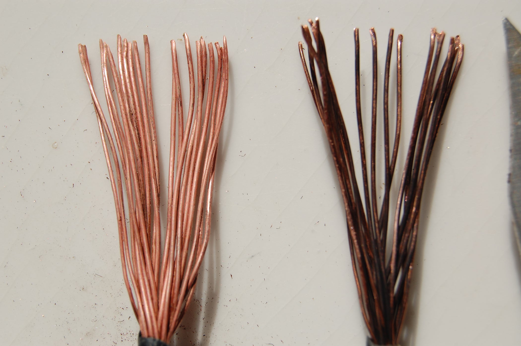
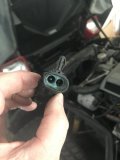
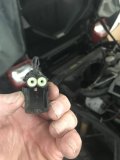
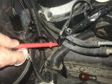
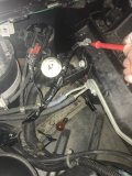
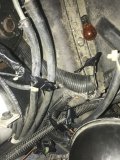
I thought I found a possible grounding short as I noted a lot of corrosion on a female connector( which had been left unconnected for years to keep the under hood lights from coming on.( see photos 1,2 and 3). If one looks at the ground diagram, it would seem that a short there could cause many problems with most of the issues cited above. However, when I pulled the connector apart, no improvement in the issues occurred. Unfortunately, I did not realize you had a link about pulling the leads out properly, so I just pulled the wires out sans leads. Hopefully, will do better on install.
I now either need a new female( not sure what to look for on the internet that will exactly fit the male connector from the hood) or the parts to disassemble the old and replace with new hardware to rewire after trying to clean all the corrosion.
3) Can anyone help with suggestions here?
Note: I do see Grumpy’s link here https://ceautoelectricsupply.com/product/2-position-weatherpack-connector-kit/
,but is this the correct connector for my 84 C4?

Again, after looking at the ground diagram, G107 is on the left radiator support.
4)Is that the ground in my photo?(5th photo)

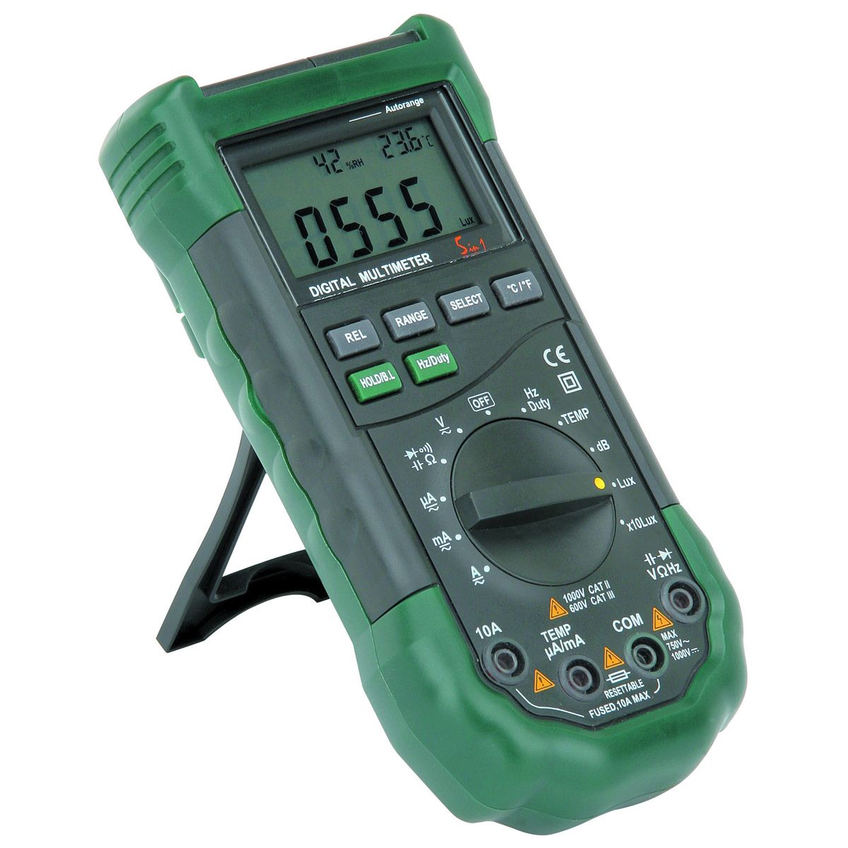
I cleaned up that one and noted no extraneous voltage there (nor to the engine exhaust manifold)when checking with the HF cheap multimeter, and attached a direct negative from battery ground to that, but no change in symptoms.

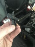
Next, after following that ground up, there is what appears to to be a connector (not on the ground diagram) that I was trying to pull apart to see if the short was higher up in the harness, but it is unclear whether that should be separable by squeezing the plastic leg, or separating it further, and then pulling apart. (See photo 4th and 6th)
5)Guidance on this point is requested.

6)I wonder if using a signal generator ( the cheap one from harbor freight) connected to fuse box on this circuit, can help me track down where the circuit is discontinuous with the ground in the front engine bay. I’m trying not to put pin holes in the wiring to test trying to find a voltage drop(although I see your link for Permatex liquid copper)

Here are some voltages at the various receptacles.
I tested the voltage at each pole of parking light/turn signal/emergency flasher receptacle on left and right sides under different “power on configurations.”

Emerg flasher powered on:
Left
.4v one pole
.37 other pole
0-.01v spring side leg

Right
8v
.4v
0-.01v

Turn signal
Left
.15v
.11v
.01-.02v

Right
10.63v
.23v
.01-02v

Parking lights alone
Left
10.75v
11.93v
0

Right
10.82v
11.93v
0

Fog lamp receptacle with bulb in place
Left (not lit)
11.57v
.02v

Right (lit)
11.49v
.05v

Thanks again for your help. I’ll apologize in advance for not finding one of your many links that answer questions.
 

Attachments

  • 5ED9D8D5-93EA-4FC8-A7DC-44133ECDD09C.jpeg
    5ED9D8D5-93EA-4FC8-A7DC-44133ECDD09C.jpeg
    80.6 KB · Views: 1
  • D5CC41F1-7FE7-49CA-8205-CE036B53CB8B.jpeg
    D5CC41F1-7FE7-49CA-8205-CE036B53CB8B.jpeg
    82.9 KB · Views: 1
  • E22F5CFF-4726-414C-9958-7F40737CA7BF.jpeg
    E22F5CFF-4726-414C-9958-7F40737CA7BF.jpeg
    79 KB · Views: 1
  • 86283D88-4079-4498-A6A5-8B74C80DB883.jpeg
    86283D88-4079-4498-A6A5-8B74C80DB883.jpeg
    196.1 KB · Views: 1
  • B442BA6A-2FCC-462C-84D7-00F63A623210.jpeg
    B442BA6A-2FCC-462C-84D7-00F63A623210.jpeg
    177.1 KB · Views: 1
  • 52C09849-2355-413F-A89B-C963994CFCEC.jpeg
    52C09849-2355-413F-A89B-C963994CFCEC.jpeg
    220.8 KB · Views: 1
I really hate to bring this up, but when ANYONE purchases "a new to them" corvette, its almost MANDATORY
your forced to purchase a factory shop manual for your exact year corvette .
in either book form or the CD you can download each page from.
it's very common to have electrical issues with c4 corvettes your dealing with a car that's over 35 years old and that probably spend decades exposed to moist air , rain, snow etc, like most of us you'll be forced to test and replace electrical connectors , bulbs, grounds fuses and fuse panels etc.
ID also replace any suspect light sockets and bulbs, and yeah there's some potential for the steering column, signal light controls to be worn or defective.
I wish I could be there to help you isolate and test, and you could help me out on a few items on my 1996 corvette
(getting under it with two recently replaced knees is a challenge)

and of course a multi meter, with test leads that are designed to pierce insulation, without permanently damaging wires
51I90G8zs7L.jpg


31JYJr9qvgL._AC_.jpg
31435mI8gqL._AC_.jpg
image_12926.jpg

bsk-1070_xl.jpg


Last edited:
I really hate to bring this up, but when ANYONE purchases "a new to them" corvette, its almost MANDATORY
your forced to purchase a factory shop manual for your exact year corvette .
in either book form or the CD you can download each page from.
it's very common to have electrical issues with c4 corvettes your dealing with a car that's over 35 years old and that probably spend decades exposed to moist air , rain, snow etc, like most of us you'll be forced to test and replace electrical connectors , bulbs, grounds fuses and fuse panels etc.
ID also replace any suspect light sockets and bulbs, and yeah there's some potential for the steering column, signal light controls to be worn or defective.
I wish I could be there to help you isolate and test, and you could help me out on a few items on my 1996 corvette
(getting under it with two recently replaced knees is a challenge)

and of course a multi meter, with test leads that are designed to pierce insulation, without permanently damaging wires
51I90G8zs7L.jpg


31JYJr9qvgL._AC_.jpg
31435mI8gqL._AC_.jpg
image_12926.jpg

bsk-1070_xl.jpg


Grumpy,
Thanks for the links you have provided.

After eliminating the ground side, my left front signal/hazzard problem was on the feed side. With the help of a shop manual, the common pathway went through the steering column and through the hazzard and turn signal switches. All the steering column wiring, minus the cruise control, were connected to a common connector. That connector is where the turn /hazards output exited as well as where the feed power entered the steering column.
The left turn signal voltage output was good on switch side while back probing, but bad on the output side, and opening that connector showed a lot of corrosion on that output to my faulty left front signal lamps. See photo for the contacts on that connector. This is likely the problem.

So a few questions follow:
When proving the rest of the circuit to the bulbs, I shunted the feed side from the turn signal flasher to the corroded connector circuit and the previously failed bulbs lit in this circuit now, but no flashing. Just to see what happens to shunting the previously intact flashing circuit on the right front, that also lit, but again no flashing. Why no flashing to either side though is a bit of a puzzle, but both sides behave the same so I think that proves the corroded connector is the only fault on that left front circuit. The only missing loads when shunting in this way are the indicator bulbs and wiring switch contact points.

Next is how to fix the corrosion. I have CRC QD electronic cleaner, but what is the best way to clean those female-side contacts (and the flat male-side also).
Is the only way to spray the cleaner into the connectors while I’m upside down and while I wear goggles and a mask to prevent ingestion/inhalation. I think there is a way to remove those connectors individually from the body, but not sure how without causing further damage, and I prefer not causing more trouble for myself.
So what procedure would you advise?

Lastly, although the link for the shop manual from Summit got me the Bishko reprint that thankfully has the wiring diagrams, unfortunately those diagrams are black and white causing some circuits to be barely visible, in the case of light blue, and invisible in the case of yellow wiring. Also some of the continuing circuit information in the extremes of the pages are missing or cut off.
I guess I will need to get the electrical supplement in color.

And by the way, if I was local to you, I would be happy to help you troubleshoot your 1996 as I often will just watch wrenching to learn stuff, and my arthritic hands may be a better match than your prosthetic knee joints.
1687053723634.jpeg
See the 4th contact up counting from bottom. 3rd looks like it could use a bit of cleaning too.
 
you should start by replacing defective pigtail connectors and gang plug connectors
a proper year shop manuals a huge help!
yes repairing a 40 year old corvette's wiring can be a P.I.T.A. but its doable and parts are available

but it takes research ideally a factory shop manual, and a multimeter and persistence
thank you for posting clear pictures, that helps
don't ignore sub linked info :like:
https://www.ebay.com/itm/275629204785 (im not sure this is what you need but do some research)
do a google/internet search for electrical connectors/pig tails for 1984 (what ever year your dealing with ) corvette


finding that elusive connector or pigtail that was damaged or melted can be a P.I.T.A. but these links may help
do a couple different internet searches like

c4 corvette electrical connectors
or
replacement electrical pigtails for c4 corvette

1984 corvette eletrical wiring diagram - Google Search


Vette2Vette

We have over 125 car parts from 1984-2004 in our 25,000 square foot indoor facility, with additional corvettes and parts arriving all the time. We offer new, used, rebuilt and reproduction parts.
www.vette2vette.com
www.vette2vette.com


http://www.crateenginedepot.com/pdfs/Pigtails.pdf

https://www.acdelco.com/parts/wires-cables

https://www.wiringproducts.com/general-motors-engine-connectors

1984 corvette eletrical wiring diagram - Google Search
http://terminalsupplyco.com/Store/Default.aspx?CAT=SF060030

https://www.bwdbrand.com/media/2827/bw11211-illustrated-connector-guide.pdf

https://www.underhoodservice.com/acdelco-releases-newly-integrated-pigtail-catalog/

https://findpigtails.com/

https://www.amazon.com/gm-pigtail/s?k=gm+pigtail

the threads have links youll need


http://garage.grumpysperformance.co...-auto-elecrtrical-connectors.3105/#post-68805

http://garage.grumpysperformance.co...trical-wiring-for-a-tbucket.10038/#post-39056

http://garage.grumpysperformance.co...vious-owner-butchered-wiring.3439/#post-19529

http://garage.grumpysperformance.com/index.php?threads/lots-of-wiring-info-diagrams.317/#post-84479

http://garage.grumpysperformance.com/index.php?threads/testing-an-alternator.3222/#post-46703

http://garage.grumpysperformance.co...urrent-flow-grounds-and-more.3504/#post-33363

http://garage.grumpysperformance.co...r-auto-elecrtrical-connectors.3090/#post-8220

http://garage.grumpysperformance.com/index.php?threads/heat-shrink-tubing.1443/#post-28050
 
Last edited:
While the vinegar/salt -then baking soda/water cleaning may be great, is it suitable for a connectors without depinning the affected wires?

If OK for the whole connector with wires, I would wonder if there is a concern about retained moisture in the connectors. How long would one need to wait for adequate drying before reconnection. I don’t have an air compressor to blow it out. Possibly, just finishing off the process by spraying the CRC electronic cleaner, if it is miscible with water, would help it dry better by evaporation.

With regard to depinning, how does one find out what tool is needed to de-pin this particular connector, and how to do it? I’ve looked at the video https://www.wiringspecialties.com/video-tutorials/connector-diy/

, and this connector was not one commented about. They make it look awfully easy.

Do I need the set of tools from https://www.wiringspecialties.com/cotepi.html , or some others including Delphi tools or the Lisle tool https://www.amazon.com/Lisle-57750-Wire-Terminal-Tool/dp/B007WQQHA2/ref=asc_df_B007WQQHA2?tag=bngsmtphsnus-20&linkCode=df0&hvadid=80882941400083&hvnetw=s&hvqmt=e&hvbmt=be&hvdev=m&hvlocint=&hvlocphy=&hvtargid=pla-4584482468295897&psc=1#immersive-view_1687225077940 from that other video https://www.amazon.com/Lisle-57750-Wire-Terminal-Tool/dp/B007WQQHA2/ref=asc_df_B007WQQHA2?tag=bngsmtphsnus-20&linkCode=df0&hvadid=80882941400083&hvnetw=s&hvqmt=e&hvbmt=be&hvdev=m&hvlocint=&hvlocphy=&hvtargid=pla-4584482468295897&psc=1#video-immersive-view_1687224955080?

Lastly, the WeatherPack 2 connector I destroyed, I think it technically is the male side metal piece with a female shroud , leading to the under hood lights, can be repaired by me by getting 2 new inserts, soldering them to the remaining wires and simply inserting them into the cleaned up connector body, or a new body.

But, as many of us C4 owners have disconnected that connector on purpose to prevent battery drain, since I’m going through this repair effort, is there a simple switch I should add in circuit, like this https://wiringproducts.com/products/red-led-oval-rocker-16-amp-12v-on-off-1-pc or another design that is better for on/off. Maybe it’s better to get the after market switched wiring harness, or maybe just switch to low current LEDs and be done with it.
 
a good soak/spray of WD 40 removes moisture (vinegar very effectively)
you also have the option of just replacing the damaged pin connectors leaving the rest in the gang plugs,
and replacing them by cutting the wire and replacing with a single connector male/female plug on both the cut wires your now reconnecting.
personally Id suggest you use heat shrink tube and solder wires you cut


Not trying to be a wise guy, but things have gotten more complicated than I remembered. There are now 37 kinds or variations of WD40 including two used for contacts, electrical parts respectively. Obviously some variations would not be appropriate.

I’m betting that your recommendation for final step drying of my connector probably involves using the classic WD40 multipurpose.
 
It was difficult finding replacement pins and connectors for my 84 Corvette through junk yards and posted links and other searches. I realized that many of the Corvette components and wiring connectors were used by a great number of other GM vehicles and some AMC models over a large number of years. While many are not used in current vehicles, there are enough around making these things available, if you know where to look. So, I found a great source for classical wiring stuff going forward. These were great guys to talk with also.

 
Last edited:
Things are coming along as I have now successfully depinned two obviously corroded / corroding pins in that multi gang connector. It certainly helped to have the right Delphi tools and advice from Darren at Haywire Inc. I now have new replacement pins as well but will try first the above vinegar/ salt method of anti corrosion.

Now it seems that some of the other Gremlins were not related to the turn signal issue. It turned out that one of the fog bulbs was burned out after checking the bulb correctly, this time.

The horn issue is where I need some further advice. I discovered that the horn relay was not functioning, but when I replaced it, the horns began blaring without pressing the horn switch. After disconnecting the leads to both horns, it became apparent that the relay was clicking repetitively, especially with slight rotation of the steering wheel. I also noticed that if I compressed the telescoping spring, that the relays were now controllable with the switch. Unfortunately , after reconnecting the horns, and after a short local drive, the horns began to blare again spontaneously inspite of the button and horn lead wire being removed.. After again disconnecting the horn leads directly, I discovered the relay was again non functional.

I believe that the culprit is in the steering column, possible a broken spring or horn contact retainer that is shorting the current path.
In the future, I will remove the steering wheel and go deeper to diagnose. My plan is to purchase in advance a new horn button lead wire, a new horn contact retainer, which appears to be an insulator, and an new leader tower, and relay.
The main problem appears to be getting a “steering wheel contact spring,” which at the moment appears unobtainium. It supposedly is common to 1984-89 vettes. I have not found the junk yards very helpful when it comes to very low ticket items like these. Nothing shows up on eBay. The part that is available is a slightly different design on 1982 and older vettes where the spring is connected to a plate. It almost seems as if purchasing that, I could disconnect the plate and do some jury rig bending of the spring. Anyone with ideas?
 
After spending time maintaining my daily driver, I got around to completing some tasks on the C4. Happy to report the left signal problem is fixed, which makes the car inspectable again in NY, although my horn will be addressed next. The under hood light corrosion issue is now fixed with soldered new connector pins which were reinserted into the cleaned up plastic connector body.

Little by little getting things done, learning a lot, increasing my useful tool collection, and onward.
 
glad to hear theres progress made!
any pictures of the work you have done?
 
glad to hear theres progress made!
any pictures of the work you have done?
Lol. Not sure a photo of an electrical connector attached to its mate, or a photo of the under hood lights on, or a video of the left front turn signal working properly is worthwhile. The same reasoning would apply for an audio/video of my horn eventually working when I press the horn button instead of it going off on its own, for that matter. But, when something more significant and telegenic gets accomplished, sure.
 
My horn is fixed and now functioning properly.
If anyone wants a detailed case study of what I found and my hypothesis of what likely happened, read on below. Otherwise, all the electrical problems that I found initially are solved, except I have not yet purchased matching LED, HID, or original halogen replacement fog lights. Also, after fixing the under-hood lights, I discovered that they do not go off even when the hood is closed, thus I need 2 new mercury switches that rest on top of each bulb. And while I’m at it, I’m going to get LED replacements, and get 2 each of new male and female weather pack connectors to make my own manual switch for each side using some wiring and 2 switches.

Now to the horn case study: Prior to removing the steering wheel, aside from the horn blasting uncontrollably when the relay was not burned out, turning the steering caused a very springy scratchy feel and sound all the time when moved, telescoped or compressed.
Also, while I thought the relay was burnt out, it again was noticed to rapidly click with any steering wheel movement. (I had disconnected the spade connectors to each horn to prevent the loud noise).

When the steering wheel came off, the horn button contact spring seemed to be loose, but I couldn’t be sure I didn’t dislocate it on my inexpert removal. Upon inspection of that spring, it appeared intact, but compared to the new used one recently purchased, one can notice a slightly elongated appearance of my original spring and its slight pulled out of round continuity of the small diameter end compared to the new used other.
1690831940883.jpeg
The larger loop of the spring was able to be replaced by me in the underside of the steering wheel plastic locking structure, which also appeared without damage. Looking further, after removing the 2 insulating thick nylon washers which sandwiched a tubular insulator that surround the central structure, the horn contact retainer (plastic) was exposed and appeared intact.
1690832398048.jpeg
However, when I tried to remove it, it cracked by my inelegant removal, or maybe it had been weakened somehow.

1690832071308.jpeg
1690832188555.jpeg
Examining how the horn worked while using a voltmeter, if the spring touched any park of the shaft while also contacting any of the 3 electrically exposed platforms that were left purposefully exposed by the plastic contact retainer, the horn/relay would be triggered. So my hypothesis is that my spring, which was left in a maximally telescoped position for a long while, had become slightly malformed and dislocated from its seated position in the underside of the steering wheel where it was free to contact the shaft where no insulation exists, especially when telescoping out.
1690832507668.jpeg
The smaller end may have gotten stuck on the plastic contact retainer at some point and weakened it, as well as distorting the spring.
1690832682870.jpeg
The plastic contact retainer was replaced, the new used spring was seated. While the plastic button lead tower piece did not appear grossly defective, it was replaced with a new tower that was very slightly different, but not effectively so. The new one also eliminated some slop that existed in the older one where the locking opening had enlarged from wear.
1690832802115.jpeg
1690832855455.jpeg

This is where the connecting button wire/spring lead) inserted. Other than easily disconnecting, the other issues were the main culprits in causing the uncontrollable horn. Although my connecting wire/spring lead was probably ok, it too was replaced.
 
Back
Top