What Can You Learn From A Parts Washer ?

Indycars

Administrator
Staff member
I can see some of the very same principles that I read about being demonstrated in these pictures about the air/fuel flow thru and engine. I have several more pics and some observation that I would like to add tomorrow, but I could just not wait, this is just too cool!!!

Can you add anything, it doesn't have to be right or wrong, but what do you see ???


Attachments

  • Connected_1999.jpg
    Connected_1999.jpg
    44.1 KB · Views: 132
  • Connected_2008.jpg
    Connected_2008.jpg
    65.1 KB · Views: 132
  • Connected_2011.jpg
    Connected_2011.jpg
    58.5 KB · Views: 132
GREAT PICTURES!
the first thing that comes to mind is that in most fuel injected engines the injectors are mounted fairly close to the intake manifold port exits and the angle of the injector spray pattern is seldom optimal, and usually placed to close to the valve and the fuel fogged into the port entrance in the heads at less that the ideal angle or distance.
If you paid attention you know DART CYLINDER HEADSmade a big deal about changes in the port design of the platinum plus head line to increase WET FLOW and while the port flow increases measured on a flow bench were not all that much better that the previous cylinder head versions the power produced tended to show increases in almost every comparison
fuel_injector_info.jpg


Spray-pattern.jpg

partly clogged injectors tend to reduce power and increase emissions

111019125145.jpg

this diagram showing the injector angle and placement is far more common that the rather ideal placement and angle shown in the first picture, notice how the injectors spray into the port runner floor, vs the idealized angle thats rarely if ever used due to packaging and clearance concerns in assembling real engines

manvalves.jpg


thats also one of the reasons the 9,13,and 18 degree heads tend to make more hp than the stock 23 degree heads , the flow past the valves more consistent and higher, as a greater portion of the flow has to make less of a change in direction as it enters the chamber, just as the open chamber heads tend to increase flow rates over the older closed chamber head designs

p113792_image_large.jpg


wet_flow1.jpg

dry flow changed little
wet_flow2.jpg

power produced improved with wet flow taken into account
AND WHY GUYS ANGLE MILL HEADS
angle1milling.jpg

angle2milling.jpg


RELATED THREADS

http://www.carcraft.com/techarticles/11 ... ewall.html

http://www.superchevy.com/technical/eng ... ewall.html

viewtopic.php?f=53&t=5199&p=15129#p15129

viewtopic.php?f=55&t=5503&p=18605&hilit=injector#p18605

viewtopic.php?f=50&t=268&p=18435&hilit=injector#p18435

viewtopic.php?f=52&t=3143&p=8387&hilit=multi+angle+valve+jobs#p8387

viewtopic.php?f=55&t=3953&p=10554&hilit=injector#p10554
 

In the picture below you can tell there is a lot of chaotic movement of the fluid particles. It is possible that some
of these are just two different particles, one behind the other and going in different directions.


We can estimate the velocity of the particles by using a few things that we know, such as:

1 - The distance of the valve margin. ( I didn't think to measure this, but typically they are ~ .060")
2 - The particle pointed out by the yellow arrow must have traveled ~ .080" when compared to the valve margin.
3 - Camera shutter speed at 1/125 sec or .008 sec.

The distance traveled by the particle would be correct if it is traveling perpendicular to the camera view. If it's not,
then it could only be longer in reality. Therefore the estimated distance would be a minimum distance and the velocity
could be even higher.

At best, all this is just an estimate of course.


Attachments

  • Chaos_2002.jpg
    Chaos_2002.jpg
    43.6 KB · Views: 115
  • Velocity_2008.jpg
    Velocity_2008.jpg
    63.5 KB · Views: 115
-Wet Flow Technology for Cylinder Heads


1/2/2010
David Hughes

Engine power technology has a new area of research that will help pro-stockers as well as RV's. Wet flow technology has to do with the air and fuel mixture that flows thru the intake ports. This is one step beyond the normal dry air-flow testing that has been the focus of engine builders for the past 60 years.

For all these years engine builders have worked with flow of "dry" air thru the intake system, and power has increased in great part because of it. However, the true medium flowing thru the ports is a mixture of air and liquid fuel. This A/F (air/fuel) mixture acts differently and responds differently to ports shapes and modifications than the wet A/F mixture. This situation has lead to the seeming contradictory situations where small, low flowing ports produce more power than larger high, flowing ports. This fact flew in the face of the rule of More, if some (air flow) is good More (air flow) must be better! Now the cylinder head ads that had listed massive air flow numbers started changing their heads to "high velocity". The higher velocity was a better answer, but the velocity needed to be harnessed, as not all high velocity heads produce good power. What the higher velocity did was atomize the fuel much better and that resulted in a more burnable mixture in the combustion chamber. Shazam! More power out of the same engine.

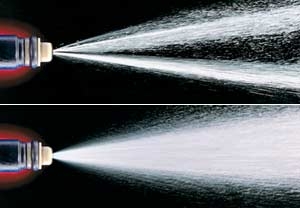
The finer the fuel droplets are (better atomized) in the combustion chamber the faster and more completely they burn. This creates more power out of the same amount of fuel and less emissions because there is less raw and unburnt gas running out of the exhaust.

Until recently designing the intake system for proper atomization has been a rather clumsy procedure of trial and error. The burn pattern (carbon residue) in the combustion chamber was "read" and changes in the intake system were made to change the pattern. The burn pattern is controlled in great part by how well the fuel is atomized as it enters the combustion chamber.

In the past clear plastic cylinder heads were built and modeled after existing heads. An air and colored fluid mixture was flowed thru them to visualize what was happing in the port. In some testing, the inside of the ports were lined with tiny pressure sensors to detect the airflow movements while the engine was running. All of this was an effort to improve the mixture reaching the combustion chamber.

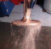
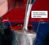
Now, the legendary, Joe Mondello who could easily be considered the father if not the grandfather of Americas cylinder head porting industry has addressed this problem. Joe has developed a wet flow system that allows viewing of the A/F mixture as it enters the combustion chamber. His patented wet flow bench blows a mixture of air and a liquid dye with a similar viscosity of gasoline thru the intake system into the combustion chamber. When operational the air/liquid mixture can be viewed, studied and modified.

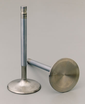
Changes to the port, valve, seat, chamber, and etc. can quickly made and retested similar to a dry flow bench operation. What we are looking for is a finely atomized A/F mixture that flows out of the valve and seat area in a pattern that will increase its burn ability. Wet flow testing can also show fuel puddling or fuel washing, in action, in the chamber.

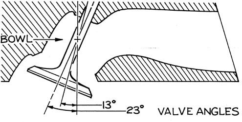
The wet flow technology is in its infancy, so it is not yet known how or what can actually be read in the flow patterns. Some of the things that have been discovered is that the long known "most critical area of the port", the seats area, seems to effect the wet flow the most. This indicates that in some cases the CFM numbers may be affected, probably in a negative way. This begs the question of which is the most important, wet or dry flow? Time will tell but early testing has shown early wet flow improvements translate into net power gains even though the dry flow numbers decreased. In the end it will be another compromise, we just need to learn how much of one to "trade-off" for the other.

One interesting discovery was that in some cases the spark plug ground strap could create a puddling situation. Simply re-indexing the plug eliminated the puddle problem and power increased.

This wet flow technology and the potential power improvements are very exciting with lots of discoveries to be made. What at first may be considered a drawback could actually prove to be a blessing in disguise. How will heads be rated or classified? The clumsy old way of rating them by cubic feet per minute {CFM} will no longer mean anything. However, as we have all found out the CFM numbers can be very misleading. The larger airflow numbers do not always translate into more power. This will be yet another example of the folly of "the biggest is always the best" type of thinking, and the advertising that preys on that ignorance.
 

My experience didn't allow me to see that 176 MPH was NOT a reasonable number. I made a mistake in the
conversion of units, so therefore below is the corrected graphic. At least I hope it's the correct graphic. :oops:

The number is not nearly as impressive and I'm sure that was also part of my problem in that I wanted
a big number. But alas the principles are still valid.


Attachments

  • Velocity_2008.jpg
    Velocity_2008.jpg
    63.5 KB · Views: 106
port speeds generally run in the 200fps-300fps range but there are ways to calculate port speeds, keep in mind that intake valve can easily be opening and closing 55 times a second or more at peak rpms and flow rates are never even over the whole port cross sectional area

http://www.wallaceracing.com/runnertorquecalc.php

http://www.superchevy.com/technical/eng ... ewall.html

http://www.rbracing-rsr.com/runnertorquecalc.html

viewtopic.php?f=52&t=462

viewtopic.php?f=52&t=322

viewtopic.php?f=52&t=1070&start=10

viewtopic.php?f=99&t=6461

viewtopic.php?f=52&t=6414
 
Back
Top