http://www.amosauto.com/Articles/Gm/Tech/na-psi-hp
NA + PSI = HP
A solid foundation, plus proven power-adder, equals longevity and performance.
By Doug Flynn - September 17, 2012 10:46 AM
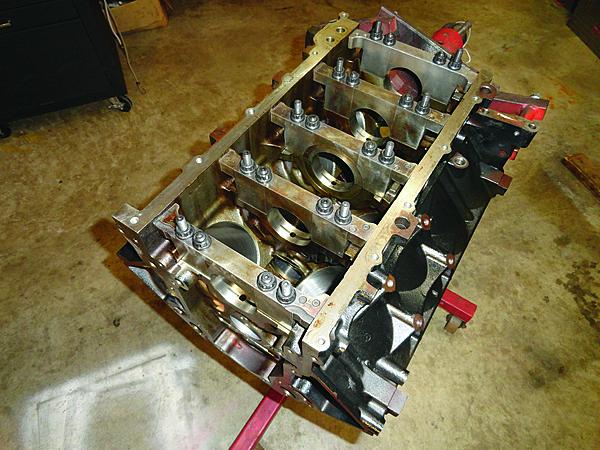
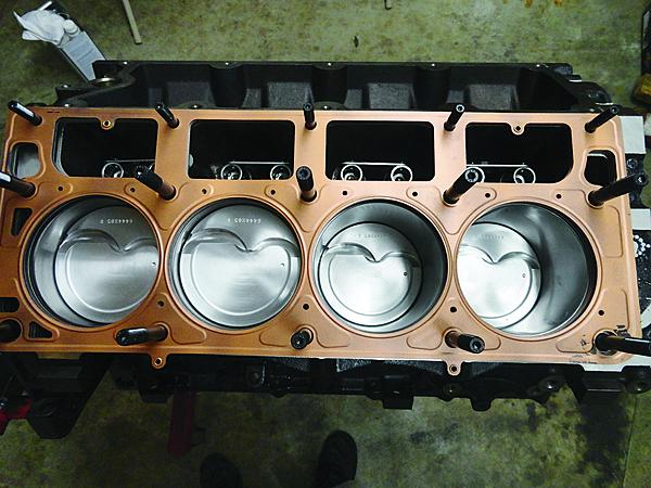
Factory LS blocks feature six-bolt main caps (two cross-bolted). Combine the iron 6L block with ARP studs and you have one stout foundation. The block was lined honed, decked, and bored to 4.006-inch.

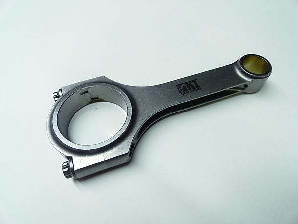
K1 Technologies H-beam rods, measuring 6.125 inches long with ARP 2000 series cap screws, will stand up to any punishment this engine will dish out.
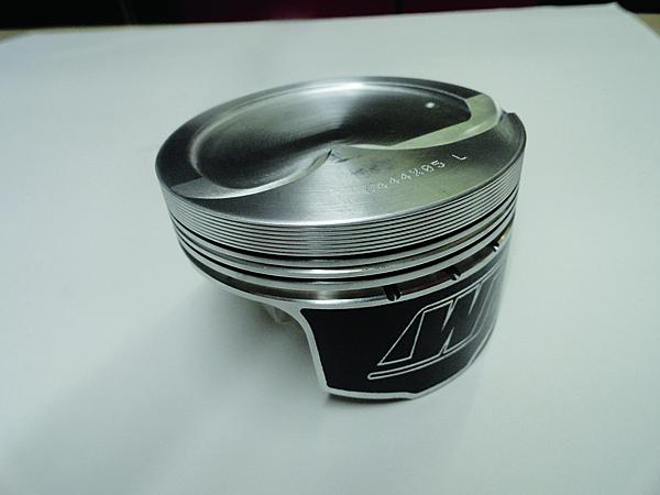
The 2618 alloy Wiseco pistons feature coated skirts, 1.2/1.2/3mm rings, and an 11cc dish for a static compression ratio of 8.8:1. The compression height is 1.300 inches, which keeps the top ring out of chamber heat. The chrome moly pins are retained with Spirolox.
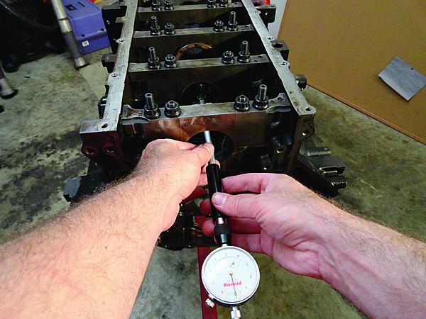
To measure main, rod, piston-to-bore and other clearances, I use a method that factors out any calibration error of the various gauges and allows the use of reasonably-priced measuring equipment. First, measure the bore with a dial bore gauge. This takes a light touch and can’t be done hastily.
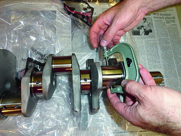
Next, measure the journal or piston and lock the micrometer. Again, you must develop a repeatable “feel”.
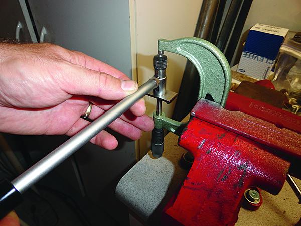
Finally, insert the dial bore gauge in the locked micrometer. Subtract this reading from what the bore measured and you have your clearance. Always measure at least twice, and if you can repeat within .0001-inch, call it good.
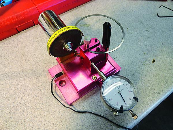
We file-fit the rings using this motorized filer. Speaking of rings, they consist of a tough nitride steel top ring, a Napier faced design second, and a standard tension oil ring.
Always use a torque wrench in combination with a stretch gauge to fasten rod bolts. Using stretch is the only way to know that a rod bolt has the proper preload necessary. Torque alone does not assure that and can vary, due to many factors.
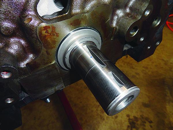
The 3.622-inch stroke K1 Technologies 4340 crank, rods, and Wiseco pistons will make for a cost-effective and stout bottom end. I changed the reluctor wheel from the original 24x to a newer style 58x. The 58x design has better signal integrity at higher engine speeds.
The K1 Technologies crank comes machined for a keyway for the harmonic balancer, something a factory crank does not have.

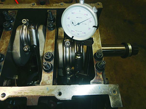
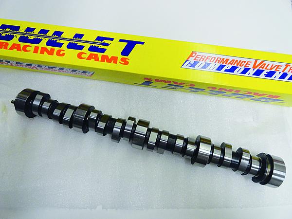
The Straub Technologies-spec’d Bullet cam came in with 230/228 degrees at .050-inch, .544/.537-inch lift on a 112 lobe separation angle, installed at a 112 degree intake centerline. It degreed dead on the money.
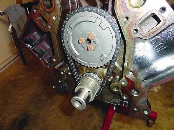
The LS2 three-bolt cam timing gear has four raised areas on it. The camshaft position sensor uses these to identify camshaft position. This is required when using a 58x crank.
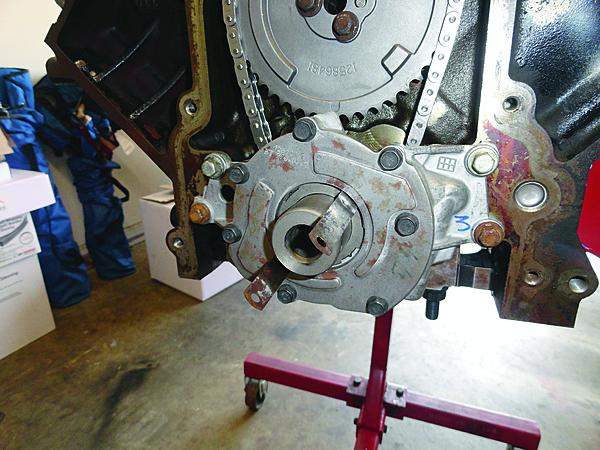
LS engines feature a gerotor-type oil pump driven off the front of the crankshaft. We used two .002-inch feeler gauges to keep the gear centered as we torqued the pump.
The ARP head studs and Cometic MLS gaskets will have no trouble keeping serious cylinder pressures were they belong.
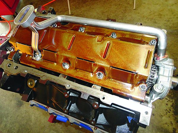
Holley supplies a matching pick-up for their cast aluminum oil pan. The factory GM windage tray is an effective piece and was retained.
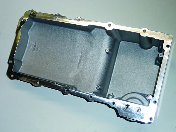
The Holley cast aluminum LS oil pan uses the factory oil filter, has an oil pick-up baffle (not installed), and fits most any chassis for an affordable price. Most factory LS oil pans have a sump design that won’t fit most muscle car chassis.
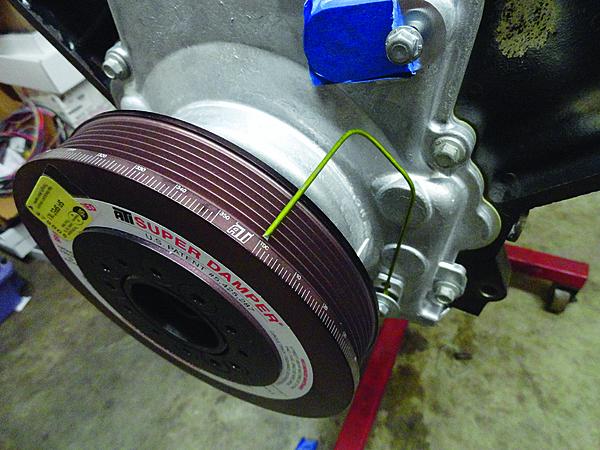
LS engines don’t come with a timing pointer. ALWAYS install a temporary one to make sure the ignition timing is correct when the engine is first started.
Image 1 of 18
2
We didn’t want a “one hit wonder” and insisted that the engine make at least 500 quarter-mile passes before we needed to go back inside the engine.
GM “LS” engines are all the rage these days with near-stock engines claiming big power whether naturally aspirated or boosted.
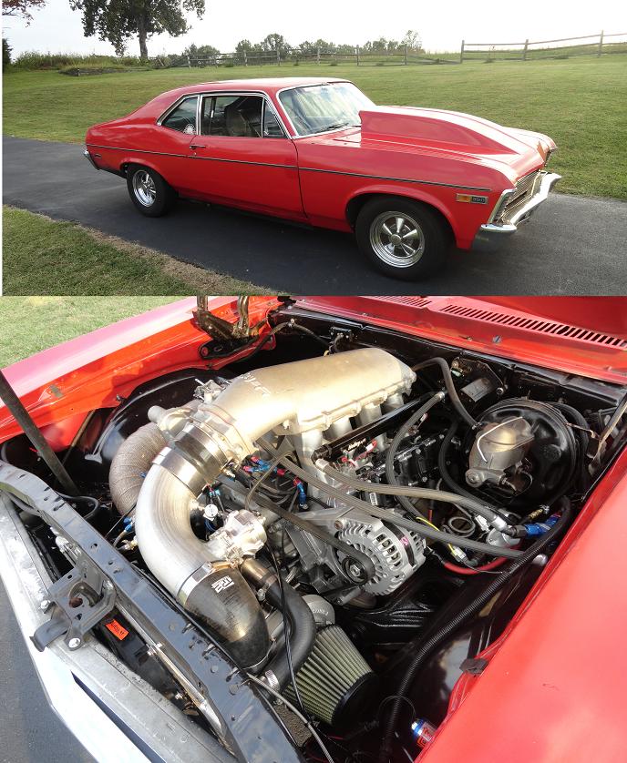
To see what all the hype was about, we decided to build one to replace the pump gas 491ci big block in a 1972 Nova street/strip car. Running 10.30s on motor and 9.50s with a small amount of nitrous is fast for a car without a trailer, but it really isn’t something you’d want to drive every day.
The goals for the project were set: Build an LS engine to be a reliable and streetable daily driver capable of deep nine-second time slips while being competitive in Hot Rod’s Drag Week event.
After determining that it would require 800 to 900 hp to meet our performance goals, the first step was to find a suitable core candidate. A search produced a complete 6.0L iron block engine with a spun main bearing for cheap (free to be exact!), so all we had to do was research which stock parts to keep, and which would need upgrading to provide exceptional reliability along with all that power.
At first, we thought about a typical, cost-effective LS build with forged pistons, good rings, upgraded rod and head bolts and a turbo thrown on top. Although there are plenty of people making that magic 1,000hp number with those pieces, we didn’t want a “one hit wonder” and insisted that the engine make at least 500 quarter-mile passes before we needed to go back inside the engine. With thoughts of just one weak link ruining the reliability and being costly in the long run, a large amount of cost-effective aftermarket parts made their way inside.
You’ve heard it before, it doesn’t matter whether the best parts are used, the most important part of any engine build is having proper machine work done. The School of Automotive Machinists (S.A.M.) in Houston, Texas, is very familiar with high horsepower LS builds, as demonstrated by their low eight-second/170 mph ’99 Camaro SS that uses a naturally aspirated LS engine and a stick transmission. So, off went the short block components and cylinder heads so they could perform their magic on them.
The S.A.M. students determined the need for a new rear main cap due to the spun bearing. And since we were updating to ARP main studs (which require a line hone job to do it right anyhow), everything worked out fine. To ensure zero water seepage, the stout Cometic head gaskets required the decks to be machined perfectly flat with a surface finish finer than 55 Ra. Next, the cylinders were bored and then honed using torque plates with their Sunnen equipment to provide .006-inch piston-to-wall clearance on the 4.005-inch pistons.
After doing hours of research, it seemed our 900hp goal was at the edge of what the factory crankshaft could handle over time. Not relishing the thought of running over it at 140-plus mph, we looked to the aftermarket. Normally, this is when you would just move up to a longer 4.000-inch stroke for a final engine size of 402 to 410ci, but when adding boost, cubes don’t always win!
Longevity dictates other considerations for a forced induction engine and a shorter stroke can help. This helps by allowing for a piston design that keeps the ring pack further from the hot crown area without the need for oil ring supports. A shorter stroke also benefits ring stability and skirt wear by limiting how far the piston extends from the bottom of the bore at BDC.
With the decision made to retain the stock 3.662-inch stroke, I found one-stop shopping with a K1 Technologies’ rotating assembly with strength that will far exceed the expected power levels, while ensuring everything will fit and balance easily. In addition to the forged 4340 crank, the kit includes 6.125-inch long K1 H-beam connecting rods fitted with ARP 2000 rod bolts. Clevite bearings were used throughout with the coated mains set to .0022-inch clearance and the uncoated rods given a little extra safety clearance of .0027-inch. The center main bearing controls thrust and was sanded to achieve the desired .006-inch of crank end play.
Since piston and ring choice is critical with any forced induction package, K1’s sister division, Wiseco, provided the forged 2618 material pistons and 1.2/1.2/3.0mm rings with coated skirts. The nitride steel compression ring, combined with a Napier design second ring and a standard tension oil ring pack will endure all our abuse, and provide long term durability. The short-block finalized at 365ci with an 8.8:1 compression ratio and more built-in durability than I’ll ever need.
Camshaft selection is one of the most important choices of any engine build, and with a turbocharger, it’s vital. We contacted Chris Straub at Straub Technologies to spec a cam because Chris specializes in designing complete valvetrain packages for a specific combination, using his own computer simulation software as well as historical data.
Our requirements were: it had to be VERY easy on the valvetrain, with great street manners, make peak power around 6,500 to 6,700 rpm, work well with 10 to 18 psi of boost and, oh yeah, spool the turbo near instantaneously. A tall order, even for an LS-based foundation. He came up with specs of 230/228 degrees of duration at .050-inch valve lift, .544/.537-inch intake and exhaust lift, on a 112 degree LSA, installed straight up on a 112 degree ICL. These specifications result in only five degrees of overlap at .050-inch lift, which really helps a street turbo application spool up at lower engine speeds. Bullet Cams made the camshaft using Chris’ specs.
The only tricky part so far in this build was learning about LS timing chains. We originally purchased a stock LS2 GM timing set, since it has a great reputation for street applications. Upon installation, there was more chain slack than we are accustomed to and with further research, learned the factory fix was to install a tensioner to stop “chain whipping”. However, we found that the 6.0L (like most truck blocks) was not drilled and tapped for this arrangement.
Had we discovered this little tidbit before final cleaning and assembly, we could have drilled and tapped it, of course. Now paranoid about the possibility of chain failure without the tensioner, we discovered the most durable single row chain available was from the GM “C5R” racing program. Although it didn’t result in less slack, it is reportedly impossible to break, it fit well and degreed in perfectly. (Note to self: next time the engine is apart, machine it for the tensioner.)
The bottom end was buttoned up with a GM LS3 oil pump (snafu #2 to be discussed next time). At least there were no surprises with the Holley cast aluminum retrofit oil pan and pick-up assembly. It is designed to retrofit LS engines in almost any chassis. The SFI-approved ATI balancer was purchased from Mike Lewis Racing Engines. The balancer was honed to the required .0008-inch press fit. LS engines are not equipped with a factory “timing pointer” like older engines, as the ignition timing is “fixed” and can’t be adjusted on factory engines. It is always best to install at least a temporary pointer and make sure the timing is correct, so when the engine is fired, there are no surprises.
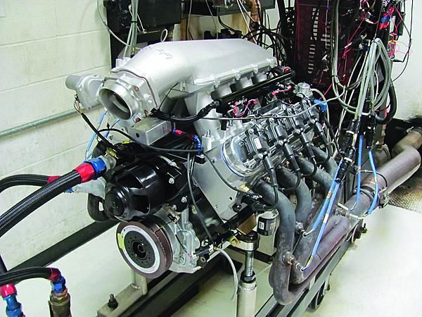
Next, we’ll install the top end of the engine as well as the turbo. We’ll dyno the engine naturally aspirated and then crank up the boost with the turbo.
NA + PSI = HP
A solid foundation, plus proven power-adder, equals longevity and performance.
By Doug Flynn - September 17, 2012 10:46 AM
Factory LS blocks feature six-bolt main caps (two cross-bolted). Combine the iron 6L block with ARP studs and you have one stout foundation. The block was lined honed, decked, and bored to 4.006-inch.
K1 Technologies H-beam rods, measuring 6.125 inches long with ARP 2000 series cap screws, will stand up to any punishment this engine will dish out.
The 2618 alloy Wiseco pistons feature coated skirts, 1.2/1.2/3mm rings, and an 11cc dish for a static compression ratio of 8.8:1. The compression height is 1.300 inches, which keeps the top ring out of chamber heat. The chrome moly pins are retained with Spirolox.
To measure main, rod, piston-to-bore and other clearances, I use a method that factors out any calibration error of the various gauges and allows the use of reasonably-priced measuring equipment. First, measure the bore with a dial bore gauge. This takes a light touch and can’t be done hastily.
Next, measure the journal or piston and lock the micrometer. Again, you must develop a repeatable “feel”.
Finally, insert the dial bore gauge in the locked micrometer. Subtract this reading from what the bore measured and you have your clearance. Always measure at least twice, and if you can repeat within .0001-inch, call it good.
We file-fit the rings using this motorized filer. Speaking of rings, they consist of a tough nitride steel top ring, a Napier faced design second, and a standard tension oil ring.
Always use a torque wrench in combination with a stretch gauge to fasten rod bolts. Using stretch is the only way to know that a rod bolt has the proper preload necessary. Torque alone does not assure that and can vary, due to many factors.
The 3.622-inch stroke K1 Technologies 4340 crank, rods, and Wiseco pistons will make for a cost-effective and stout bottom end. I changed the reluctor wheel from the original 24x to a newer style 58x. The 58x design has better signal integrity at higher engine speeds.
The K1 Technologies crank comes machined for a keyway for the harmonic balancer, something a factory crank does not have.
The Straub Technologies-spec’d Bullet cam came in with 230/228 degrees at .050-inch, .544/.537-inch lift on a 112 lobe separation angle, installed at a 112 degree intake centerline. It degreed dead on the money.
The LS2 three-bolt cam timing gear has four raised areas on it. The camshaft position sensor uses these to identify camshaft position. This is required when using a 58x crank.
LS engines feature a gerotor-type oil pump driven off the front of the crankshaft. We used two .002-inch feeler gauges to keep the gear centered as we torqued the pump.
The ARP head studs and Cometic MLS gaskets will have no trouble keeping serious cylinder pressures were they belong.
Holley supplies a matching pick-up for their cast aluminum oil pan. The factory GM windage tray is an effective piece and was retained.
The Holley cast aluminum LS oil pan uses the factory oil filter, has an oil pick-up baffle (not installed), and fits most any chassis for an affordable price. Most factory LS oil pans have a sump design that won’t fit most muscle car chassis.
LS engines don’t come with a timing pointer. ALWAYS install a temporary one to make sure the ignition timing is correct when the engine is first started.
Image 1 of 18
2
We didn’t want a “one hit wonder” and insisted that the engine make at least 500 quarter-mile passes before we needed to go back inside the engine.
GM “LS” engines are all the rage these days with near-stock engines claiming big power whether naturally aspirated or boosted.
To see what all the hype was about, we decided to build one to replace the pump gas 491ci big block in a 1972 Nova street/strip car. Running 10.30s on motor and 9.50s with a small amount of nitrous is fast for a car without a trailer, but it really isn’t something you’d want to drive every day.
The goals for the project were set: Build an LS engine to be a reliable and streetable daily driver capable of deep nine-second time slips while being competitive in Hot Rod’s Drag Week event.
After determining that it would require 800 to 900 hp to meet our performance goals, the first step was to find a suitable core candidate. A search produced a complete 6.0L iron block engine with a spun main bearing for cheap (free to be exact!), so all we had to do was research which stock parts to keep, and which would need upgrading to provide exceptional reliability along with all that power.
At first, we thought about a typical, cost-effective LS build with forged pistons, good rings, upgraded rod and head bolts and a turbo thrown on top. Although there are plenty of people making that magic 1,000hp number with those pieces, we didn’t want a “one hit wonder” and insisted that the engine make at least 500 quarter-mile passes before we needed to go back inside the engine. With thoughts of just one weak link ruining the reliability and being costly in the long run, a large amount of cost-effective aftermarket parts made their way inside.
You’ve heard it before, it doesn’t matter whether the best parts are used, the most important part of any engine build is having proper machine work done. The School of Automotive Machinists (S.A.M.) in Houston, Texas, is very familiar with high horsepower LS builds, as demonstrated by their low eight-second/170 mph ’99 Camaro SS that uses a naturally aspirated LS engine and a stick transmission. So, off went the short block components and cylinder heads so they could perform their magic on them.
The S.A.M. students determined the need for a new rear main cap due to the spun bearing. And since we were updating to ARP main studs (which require a line hone job to do it right anyhow), everything worked out fine. To ensure zero water seepage, the stout Cometic head gaskets required the decks to be machined perfectly flat with a surface finish finer than 55 Ra. Next, the cylinders were bored and then honed using torque plates with their Sunnen equipment to provide .006-inch piston-to-wall clearance on the 4.005-inch pistons.
After doing hours of research, it seemed our 900hp goal was at the edge of what the factory crankshaft could handle over time. Not relishing the thought of running over it at 140-plus mph, we looked to the aftermarket. Normally, this is when you would just move up to a longer 4.000-inch stroke for a final engine size of 402 to 410ci, but when adding boost, cubes don’t always win!
Longevity dictates other considerations for a forced induction engine and a shorter stroke can help. This helps by allowing for a piston design that keeps the ring pack further from the hot crown area without the need for oil ring supports. A shorter stroke also benefits ring stability and skirt wear by limiting how far the piston extends from the bottom of the bore at BDC.
With the decision made to retain the stock 3.662-inch stroke, I found one-stop shopping with a K1 Technologies’ rotating assembly with strength that will far exceed the expected power levels, while ensuring everything will fit and balance easily. In addition to the forged 4340 crank, the kit includes 6.125-inch long K1 H-beam connecting rods fitted with ARP 2000 rod bolts. Clevite bearings were used throughout with the coated mains set to .0022-inch clearance and the uncoated rods given a little extra safety clearance of .0027-inch. The center main bearing controls thrust and was sanded to achieve the desired .006-inch of crank end play.
Since piston and ring choice is critical with any forced induction package, K1’s sister division, Wiseco, provided the forged 2618 material pistons and 1.2/1.2/3.0mm rings with coated skirts. The nitride steel compression ring, combined with a Napier design second ring and a standard tension oil ring pack will endure all our abuse, and provide long term durability. The short-block finalized at 365ci with an 8.8:1 compression ratio and more built-in durability than I’ll ever need.
Camshaft selection is one of the most important choices of any engine build, and with a turbocharger, it’s vital. We contacted Chris Straub at Straub Technologies to spec a cam because Chris specializes in designing complete valvetrain packages for a specific combination, using his own computer simulation software as well as historical data.
Our requirements were: it had to be VERY easy on the valvetrain, with great street manners, make peak power around 6,500 to 6,700 rpm, work well with 10 to 18 psi of boost and, oh yeah, spool the turbo near instantaneously. A tall order, even for an LS-based foundation. He came up with specs of 230/228 degrees of duration at .050-inch valve lift, .544/.537-inch intake and exhaust lift, on a 112 degree LSA, installed straight up on a 112 degree ICL. These specifications result in only five degrees of overlap at .050-inch lift, which really helps a street turbo application spool up at lower engine speeds. Bullet Cams made the camshaft using Chris’ specs.
The only tricky part so far in this build was learning about LS timing chains. We originally purchased a stock LS2 GM timing set, since it has a great reputation for street applications. Upon installation, there was more chain slack than we are accustomed to and with further research, learned the factory fix was to install a tensioner to stop “chain whipping”. However, we found that the 6.0L (like most truck blocks) was not drilled and tapped for this arrangement.
Had we discovered this little tidbit before final cleaning and assembly, we could have drilled and tapped it, of course. Now paranoid about the possibility of chain failure without the tensioner, we discovered the most durable single row chain available was from the GM “C5R” racing program. Although it didn’t result in less slack, it is reportedly impossible to break, it fit well and degreed in perfectly. (Note to self: next time the engine is apart, machine it for the tensioner.)
The bottom end was buttoned up with a GM LS3 oil pump (snafu #2 to be discussed next time). At least there were no surprises with the Holley cast aluminum retrofit oil pan and pick-up assembly. It is designed to retrofit LS engines in almost any chassis. The SFI-approved ATI balancer was purchased from Mike Lewis Racing Engines. The balancer was honed to the required .0008-inch press fit. LS engines are not equipped with a factory “timing pointer” like older engines, as the ignition timing is “fixed” and can’t be adjusted on factory engines. It is always best to install at least a temporary pointer and make sure the timing is correct, so when the engine is fired, there are no surprises.
Next, we’ll install the top end of the engine as well as the turbo. We’ll dyno the engine naturally aspirated and then crank up the boost with the turbo.
 , due to changing to a full cage, 4L80E, and other items. Weighs 3850 with me in it. It's a pig.