How to Build Racing Engines: Engine Bearings Guide
APRIL 6, 2015 BY
MUSCLE CAR DIY
Virtually all modern engines use bearing shell inserts for the crankshaft, rods, and camshaft. Mains and rods use a split bearing with upper and lower half-shells. Cam bearings are mostly single-piece, ring-style inserts that are pressed in place with an interference fit in each housing bore. Most bearing inserts have a thick metal backing made of aluminum or steel to maintain their shape.
 This Tech Tip is From the Full Book, COMPETITION ENGINE BUILDING. For a comprehensive guide on this entire subject you can visit this link:
LEARN MORE ABOUT THIS BOOK HERE
SHARE THIS ARTICLE: Please feel free to share this article on Facebook, in Forums, or with any Clubs you participate in. You can copy and paste this link to share:
https://musclecardiy.com/performance/how-to-build-racing-engines-engine-bearings-guide/
The inserts are coated with copper or Babbitt material, which usually consists of copper, tin, and antimony depending on the application. Bearing Babbitt is relatively soft. This allows it to embed small particles of dirt and debris and prevent them from damaging the journal surface. In a race engine, embedability is often sacrificed in favor of high-fatigue strength and the ability to carry higher loads—the idea being that race engines have highly filtered oil that is changed frequently.
Lower main bearings must have full load-carrying capacity. Grooved bearings should never be used on the lower half of the bearing shell. Again, maintaining the load-carrying capacity of the hydrodynamic wedge via proper clearances and oil pressure is the primary goal. Rod bearings are not grooved because they are fully loaded all the way around.
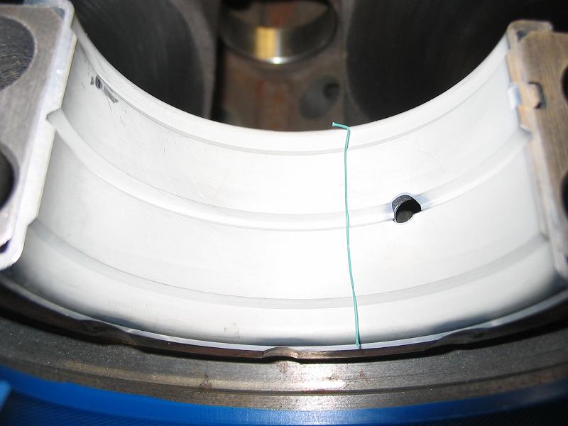
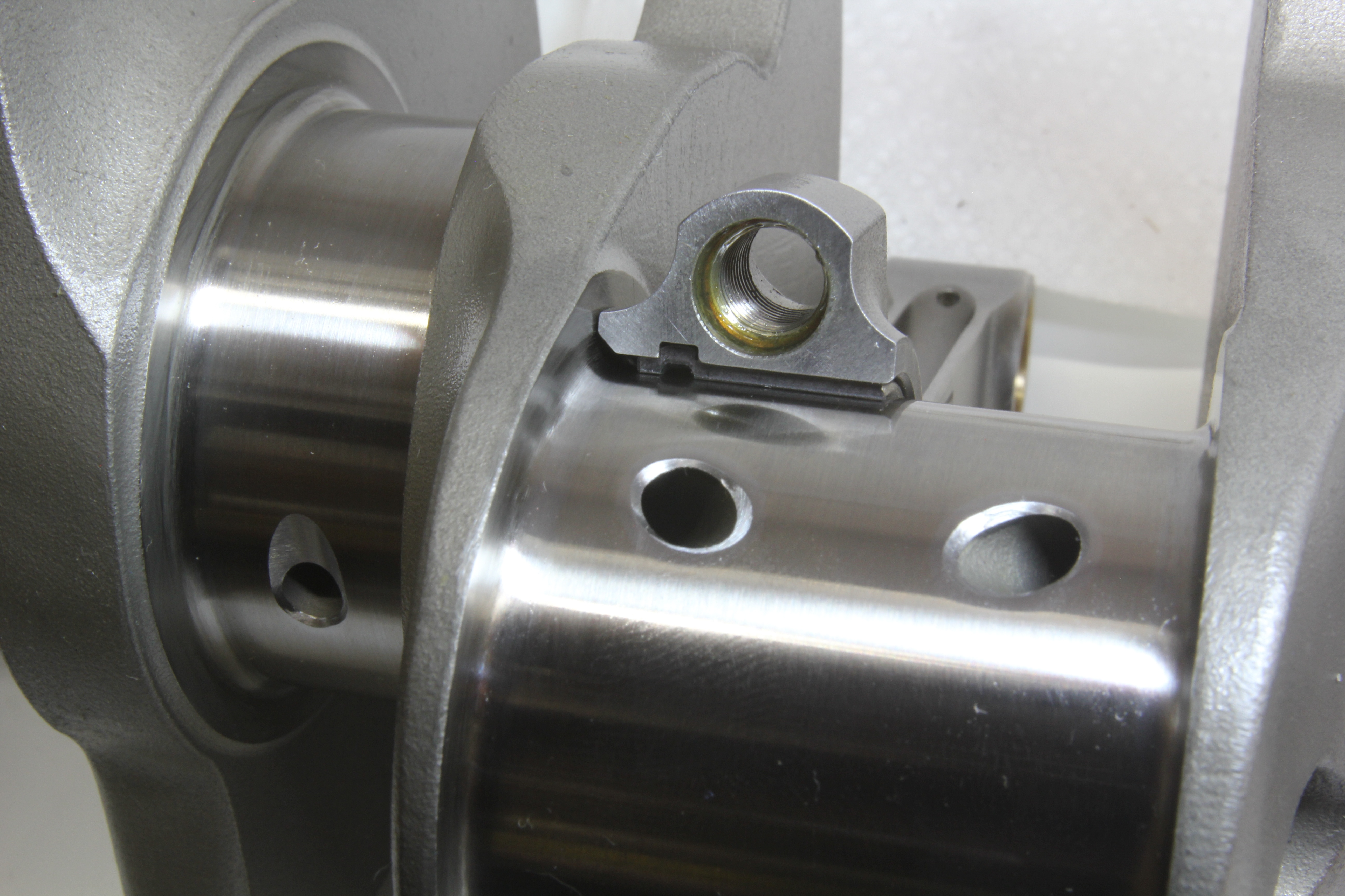
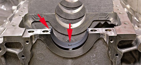
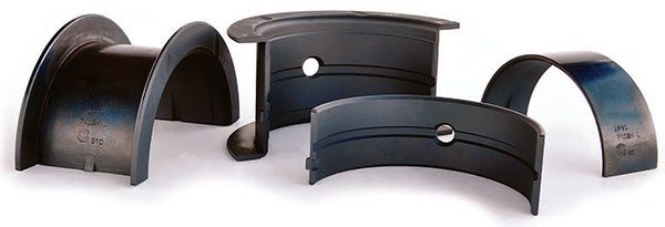
Note how this Calico main bearing extends slightly beyond the hous¬ing bore. This is the bearing crush that helps the tang lock the bear¬ing in the housing bore. Both bear¬ing shells have a small amount of crush built into them. When torque is applied to the main cap bolts the shells crush against each other forcing them firmly against the housing bore.
Arrows indicate the oiling hole and groove in the upper main bearing shell and the locator tang used to position each half shell in the bearing housing bore. This Calico coated main bearing illustrates bearing spread or the spring effect that holds the bearings in place during assembly.
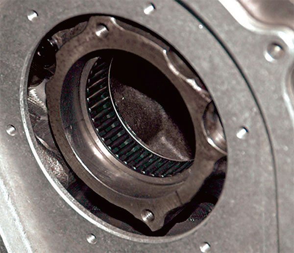
Roller cam bearings are used primarily to reduce friction and lower the total volume of engine oil flow. This lessens the load on the oil pump and helps to reduce windage in the crankcase.
Tri-metal bearings are the preferred bearing for all race applications except perhaps the extremely high-load environment of blown fuel and alcohol engines where short-duration applications require a softer Babbitt material to absorb shock loads. Tri-metal bearings consist of a hard steel shell to provide conformability and load-bearing capacity. The shells are then coated with copper, lead, and tin to provide the desired characteristics. The bearing shell surface is first treated with a copper micro-structure that incorporates minute pockets. This matrix is then covered with an overlay of a tin-copper mix or lead-indium.
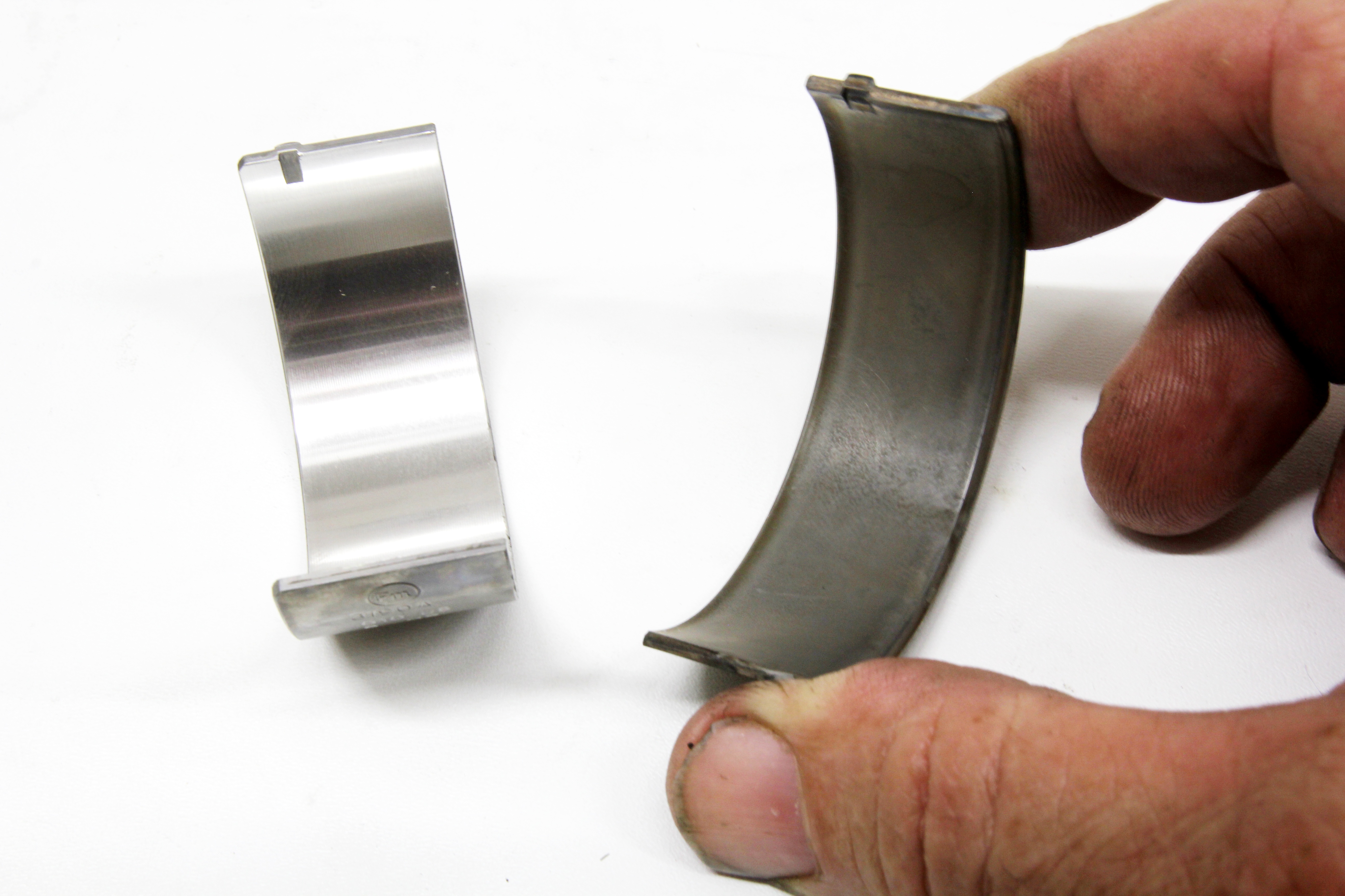
Examine a bearing shell closely and note that it fits snugly in the housing bore with a noticeable amount of tension (called spread) and extends beyond the parting line of the bore. This small degree of tension and oversize on both shells provides bearing crush to increase the contact friction between the bearing back and the housing bore and help the bearing tang lock the bearing in place so it can’t spin. This is called conformability.
In the case of aluminum rods, high thermal expansion causes the rod to relax its grip on the bearing even with adequate bearing crush. The solution is a dowel-pinned bearing. All aluminum rods come pre-fitted with a fixed dowel in the rod cap. All race bearing manufacturers make rod bearings with the dowel hole pre-drilled.
Characteristics of Engine Bearings
The physical characteristics of engine bearings vary with the application, but it is important to recognize and take advantage of the primary characteristics associated with all engine bearings.
Crush
This refers to the characteristic that forces or crushes the bearing into its housing bore. This is done to assist the bearing tang in preventing the bearing from spinning. Race engines with higher loads require bearings with more crush. Bearing manufacturers are very precise in their tolerances, making it incumbent upon the engine builder to check and adjust bearing crush. This is done primarily by precise machining of the bearing housing bores to exact specifications. In the range of journal sizes for most racing engines, the target bearing crush is typically about .015 to .016 inch for rod bearings and .019 inch for main bearings.
Eccentricity
Bearing inserts do not maintain uniform thickness throughout their circumference. They are thickest at the center of the bearing and taper toward the parting lines, creating a very slight eccentric oval shape. This is necessary to accommodate bore distortion under extremely high load conditions. While very slight, these minimal dimensional changes must be spot on to prevent undesirable engine damage.
Spread
Bearing shells also incorporate a slight degree of spread, which in effect spring loads or preloads each insert against the housing bore to lock it in place. Spread is incorporated as an assembly aid to hold the bearings in place during engine assembly. A small amount of effort is required to force the bearing inset into place during assembly.
Parting-Line Relief
Bearing inserts are slightly thinned beginning approximately .375 inch from each parting line to prevent the bearing from bulging inward and contacting the bearing journal when the bearing is crushed in its housing bore. This prevents unwanted contact when the big end distorts and tends to pinch the bearing upon piston reversal (at TDC). This is why you cannot measure bearing clearances in the vicinity of the parting lines.
Chamfer
Most race engine bearings are pre-chamfered on the edge facing the crank throw to accommodate large journal fillet radii. This does not excuse the competent engine builder from checking each insert in place to ensure that the chamfer provides adequate clearance.
Oiling Grooves
Most main bearings are grooved on the upper half only, leaving the full load-carrying capacity available on the ungrooved bottom half. It is important to remember that any groove or journal chamfer introduces an interruption in the hydrodynamic oil wedge causing a partial collapse. This is critical since the wedge’s greatest load-carrying ability is near the center of the bearing and tapers off toward each side due to oil leakage from the bearing. Manufacturers do not recommend extending grooves into the lower bearing inserts. The oil groove in the upper insert provides the oil supply for the rod bearings. Also, the insert with the oil feed hole must go in the block and not in the main bearing cap.
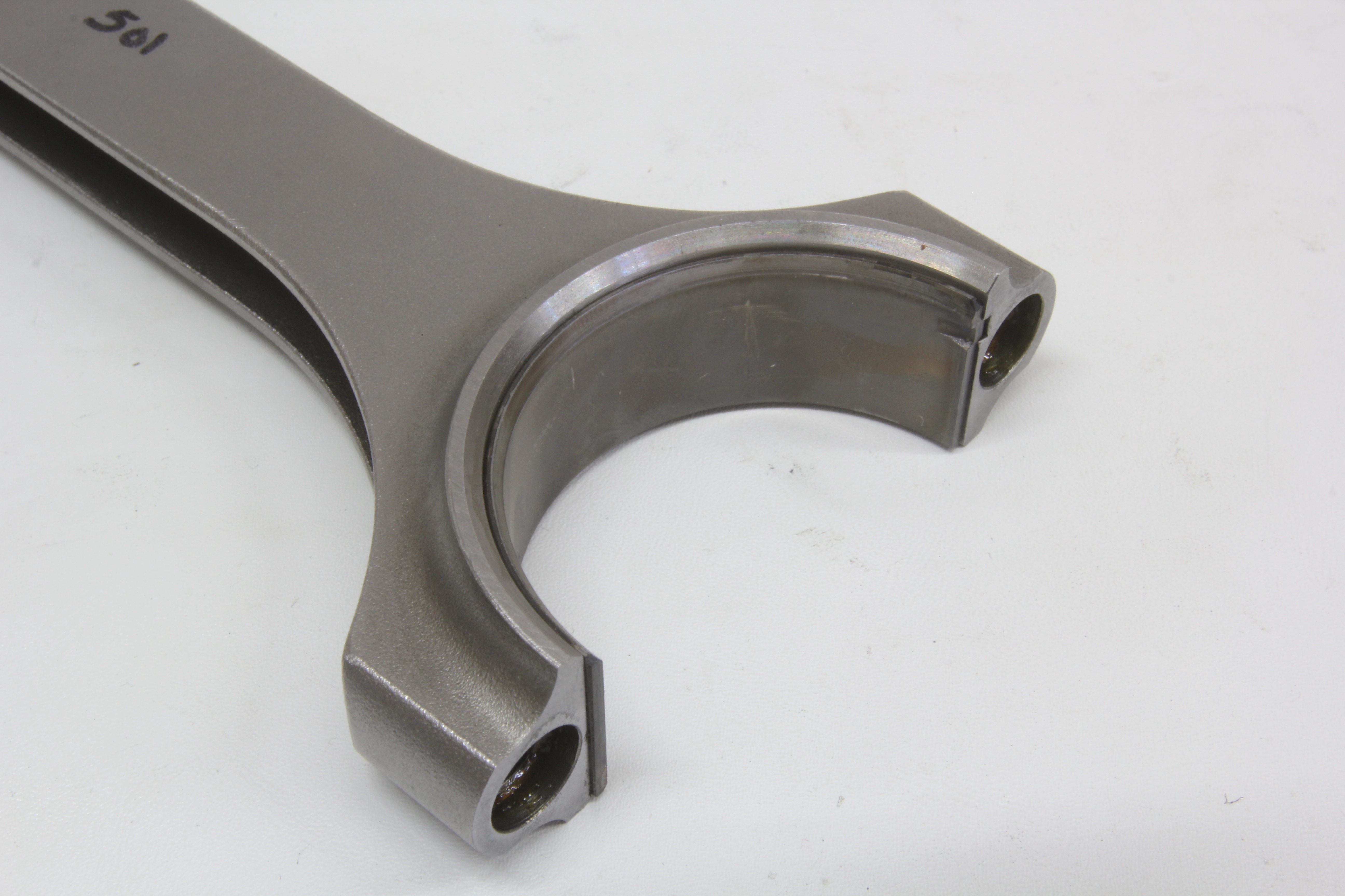
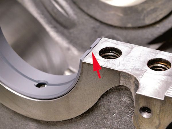
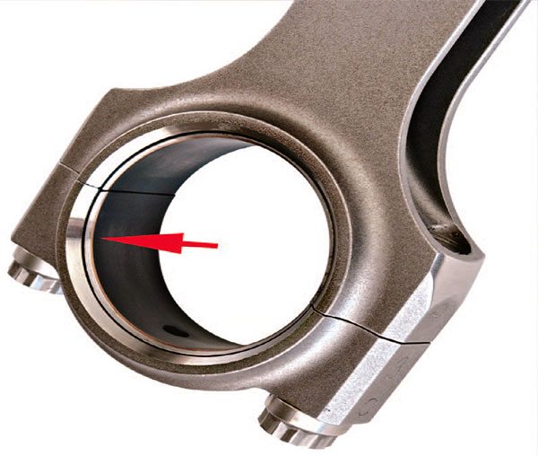
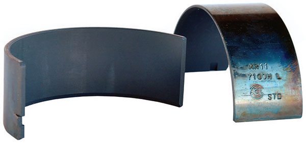
The bearing chamfer on rod bearings prevents contact with the fillet radius on the rod journal. Note how the bear¬ing shell chamfer closely matches the chamfer on the connecting rod.
Size
Engine bearings come in standard, undersize, or oversize depending on the journal size. Unlike street engines, most true racing engines rarely incorporate crankshafts with journals that have been turned down from standard size. Manufacturers do, however, provide special .001-inch-plus-one inserts that can be used to fine-tune clearances. Builders often use a standard shell on one side and a .001-over shell on the other to adjust the clearance by a few tenths.
Tang Depth
One important clearance that many builders overlook because they assume it is correct is bearing tang depth. If incorrect, it can prevent the bearing from properly seating in the housing bore and ultimately lead to insufficient clearance and probable engine damage. While this is normally not an issue with high-quality aftermarket racing connecting rods, it is nonetheless part of the essential “check everything twice” philosophy that top engine builders practice.
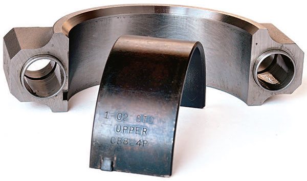
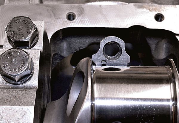
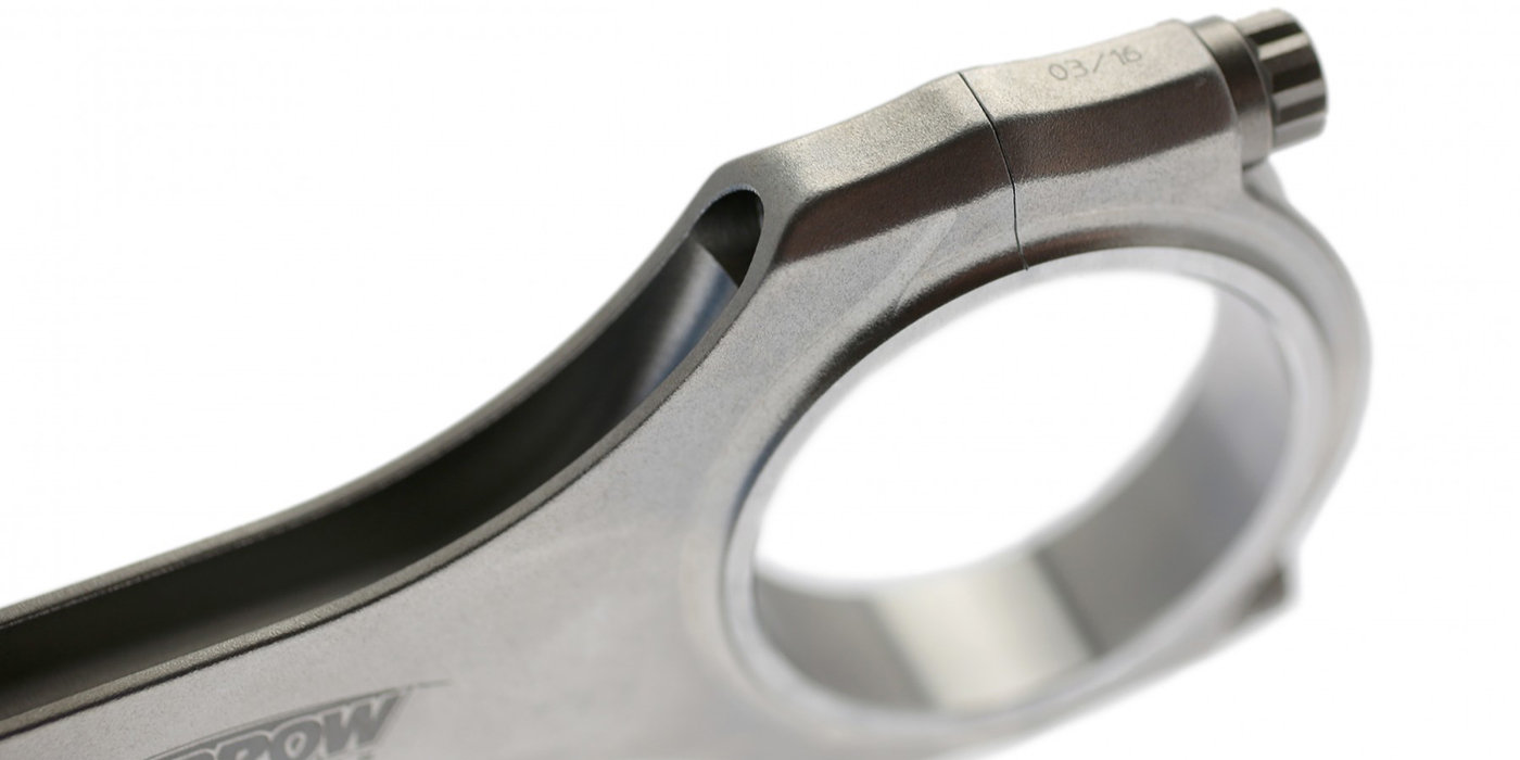
This bearing has been run in the adjacent Carrillo rod cap. Note the even surface contact pattern between the back of the bearing insert and the rod cap bore with no sign of movement.
Coatings
Bearing coatings have become commonplace in many racing engines. They reduce friction and improve heat transfer, which generally permits tighter clearances, but they are not a cure-all for bearing issues. They possess better survivability characteristics that can help save a bearing during brief periods of low oil pressure. While they do support tighter clearances, they are not a substitute for the minimum safe clearance. All good engine builders know that being a little loose is better than being a little tight, especially when it helps you finish a race that might otherwise end prematurely due to engine failure.
Polishing
All bearing manufacturers recommend installing bearings without modifications other than perhaps increasing the chamfer if it is found to be insufficient. Some builders still insist on polishing their bearings with a variety of materials from newsprint to the more common Scotch-Brite pad.
Some suggest that the coating applied by the manufacturer comes off and wads up in small chunks. If that is the case it probably has more to do with insufficient clearance than a problem with the coating, which manufacturers have spent untold sums on perfecting. Interestingly, you won’t see many builders polishing bearings with high-tech coatings, which seem to be more readily accepted.
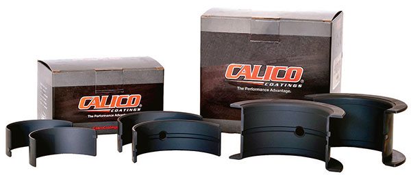
Coated bearings like these from Calico Coatings are favored because they reduce friction, permit tighter clearances, and increase survivability in the event of a temporary low oil pressure event.
Another trick practiced by some builders is polishing the backs of the bearings to theoretically improve the contact surface between the bearing and the housing bore. This may or may not provide some benefit, but it is undoubtedly less harmful than polishing the actual bearing surface where the coating is designed to help wit h initial fire-up and break-in.
Roller Cam Bearings
Many race engines incorporate roller cam bearings to reduce friction, but they are not necessary in every case. Standard cam bearings are employed in many successful race engines with great success. Roller bearings require a block designed or machined to accept them and their chief advantage is their high load-carrying ability with valvespring pressures that approach or exceed 1,000 pounds.
Because the rollers are splash oiled off the spinning crankshaft they do not require pressurized oiling. When the bearings are press fit in the block they cover the oil feed holes for the camshaft, reducing oil flow volume through the engine with less oil through the pump, hence less drag. That said, some builders shy away from rollers because of the havoc they wreak when they fail. In many cases they install larger diameter Babbitt bearings with good results. It all depends on the combination and how hard you stress the cam.
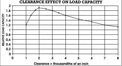
Clearances
Consistency is the cardinal rule of bearing clearances. Always set clearances the same way and with the same equipment. Engine bearings and the journals they run on are also temperature sensitive with regard to size. Clearances are used to accommodate thermal growth, but the components themselves should always be set at a consistent temperature for best results. If you’re working in a cold shop, don’t check clearances with bearings you just retrieved from a warm storage room.
The same goes for measuring equipment. Bearings, crankshafts, rods, and micrometers are manufactured from various steels that expand and contract differently according to temperature. Micrometers are designed to be used at a standardized temperature of 68 degrees F. For best results, all components and measuring equipment should be close to the same temperature.
Main Bearings
Main bearing preparation and installation must be preceded by proper housing bore dimensional preparation and careful deburring of the main caps and housing bored edges. No bearing should be fitted prior to checking for proper tang depth.
Rod Bearings
Quality racing rod bearings are very consistent in their manufacture. An issue with clearances is that it is almost always related to inconsistent journal sizes or housing bore diameters. All engine builders have preferences when it comes to checking rod bearing clearances. The procedure is critical because we are taking about tenths of a thousandth of an inch.
Many builders skip the procedure of measuring the rod housing bore diameters, but this is the first place where something can go wrong. Measuring the housing bores and writing them down is useful later when clearance issues crop up and you are trying to determine which bearings can be swapped to a different housing bore to achieve the proper clearance. Measuring and recording the housing bores is the mark of an experienced quality engine builder. Those figures may also be useful later if a bearing issue arises and you are trying to determine what caused it.
Many builders like to set their dial bore gauge to the rod journal size and read the clearance on the dial indicator. This is fine if the rod journals are consistent. Others prefer to set the dial bore gauge to a common journal diameter and calculate the clearances. This allows them to measure all the rod bearing inside diameters based on one setting.
With racing engines you can never take too much time or care so it’s best to work slowly and measure each journal and bearing independently. Write the journal number and the clearance on the back of the bearing shell to avoid mixing them up. If the bearing shells are identical, also mark which one is the top half and which is the bottom half. It is not uncommon for a tight housing bore diameter and a slightly oversized rod journal to stack the tolerance beyond the target rod bearing clearance.
The common cure for clearance issues is most often the use of undersize or oversize bearings that are offered in +.001 or -.001 with an X-suffix on the part number. An example would be the Clevite series available in -9, -10, and -11 (or 10X) and -10, -20, and -21, which allow you to set precision clearances even on cranks that have been ground .010- and .020-inch undersize. These sizes can even be mixed with standard-size shells to home in on exact clearances. For example, you can combine one standard-size half-shell with a plus-one or minus-one half-shell to reach a specific clearance.
In theory, and most often in practice, mixing half-shells increases or decreases the clearance by .0005 inch. When you do this it is best to use the thicker bearing on the upper half of the rod where it can supply additional load-carrying capacity. Note also that bearings are purposely made thinner at the parting line to accommodate the pinch effect of the housing bore when the rod stretches as the piston reverses direction at TDC.
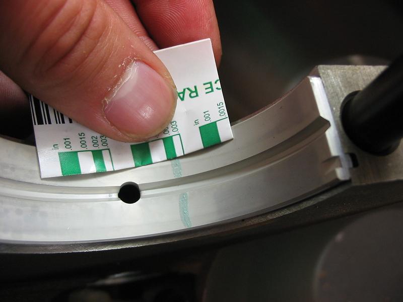
Never measure bearing clearances near the parting line. They are always off. Always measure them 90 degrees from the parting line and in line with the beam of the rod.
Bearing Failures
Bearing issues are a clear sign that something is dimensionally incorrect, overstressed, or exposed to excessive heat and/or dirty oil. Most bearing problems can be traced to improper machining, incorrect clearances, or sloppy assembly techniques. Evaluating bearings upon disassembly is an important step that many engine builders ignore completely, yet it can often tell them many things about the engine’s performance even if the bearings look perfect.
You can pretty much divide bearing failures into two primary categories: assembly problems and operational problems. Dirt and foreign material can contaminate the bearing environment in either category, so it is critical to determine the source and to always practice squeaky-clean assembly techniques and engine maintenance practices.
Assembly Problems
The following are the primary causes of bearing problems initiated at the engine assembly stage.
- Incorrect clearances
- Improper bearing crush
- Inadequate lubrication
- Improper fillet radius chamfer
- Improper tang fitment
- Dirt behind the bearing insert
During assembly, small particles of dirt can inadvertently be captured between the bearing back and the housing bore. This debris (which is often hard to detect) resides behind the bearing, deforming it outward toward the crank journal where loss of clearance can initiate localized overheating and bearing flaking. In severe cases it causes contact distress that typically leads to early failure.
The cure is to closely inspect each housing bore and both sides of the bearing insert prior to installing it. Close examination of the bearing inserts and housing bores using a magnifying glass is a sign of a quality engine builder. Appropriate de-burring with detailed inspection of the bearing tangs and their fitment is essential.
Even within the cleanest environment it is possible for dirt particles to contaminate the bearings during assembly. When small particles of dirt find their way between the bearing insert and the housing bore they initiate a local stress source and often deform the bearing with “high spots” that may contact the crank journal. Similar high spots also occur when dirt embeds itself on the bearing surface. This displaces insert material around the particle causing a buildup of material that may be greater than the available clearance. The results may scratch the journal or foster a condition where more and more material becomes displaced causing the bearing to begin flaking or coming apart.
The best cure is a cleaning regimen that includes thorough washing in hot water and detergents incorporating a strong degreasing agent.
Operational Problems
Checking bearings after a race or after a season of racing is a basic necessity. Under the best conditions with properly machined and lubricated parts, the bearings and the crank journals should experience little to no contact under all operating conditions except in circumstances such as severe overheating, pump failure, or debris in the oiling system. Frequent checks help identify problem areas and suggest the correct fix, which may not necessarily be the most convenient or the least expensive, but is probably absolutely necessary.
An out-of-round bore and/or excessive crush display similar characteristics. When the housing bore is out-of-round, bearings are excessively worn near the parting faces. According to Clevite this problem is often seen in rod bearings exposed to high RPM and high inertial loads where the rod bore becomes oblong, or because of misaligned rod and piston combinations, or rods that are slightly bent.
In the case of main bearings, thermal distortion caused by over-torquing cylinder head and intake manifold bolts when the engine is hot often promotes an out-of-round bore. When the bearing housing bore deflects it forces the parting ends of the bearing closer to the crank reducing necessary oil clearance due to the pinching effect on the crank. With intermittent oiling, metal-to-metal contact occurs and, over time, the bearing fails.
Excessive bearing crush promotes a similar effect if the bearing housing bore is carelessly machined or the bearing cap is over-torqued. According to Clevite, excessive crush condition results in a wear pattern across more than three-quarters of the bearing surface with the worst damage near the parting line. In this case the ends of the bearing inserts at the parting line exhibit excessive wear caused by excessive crushing force that distorts the bearing shell insert.
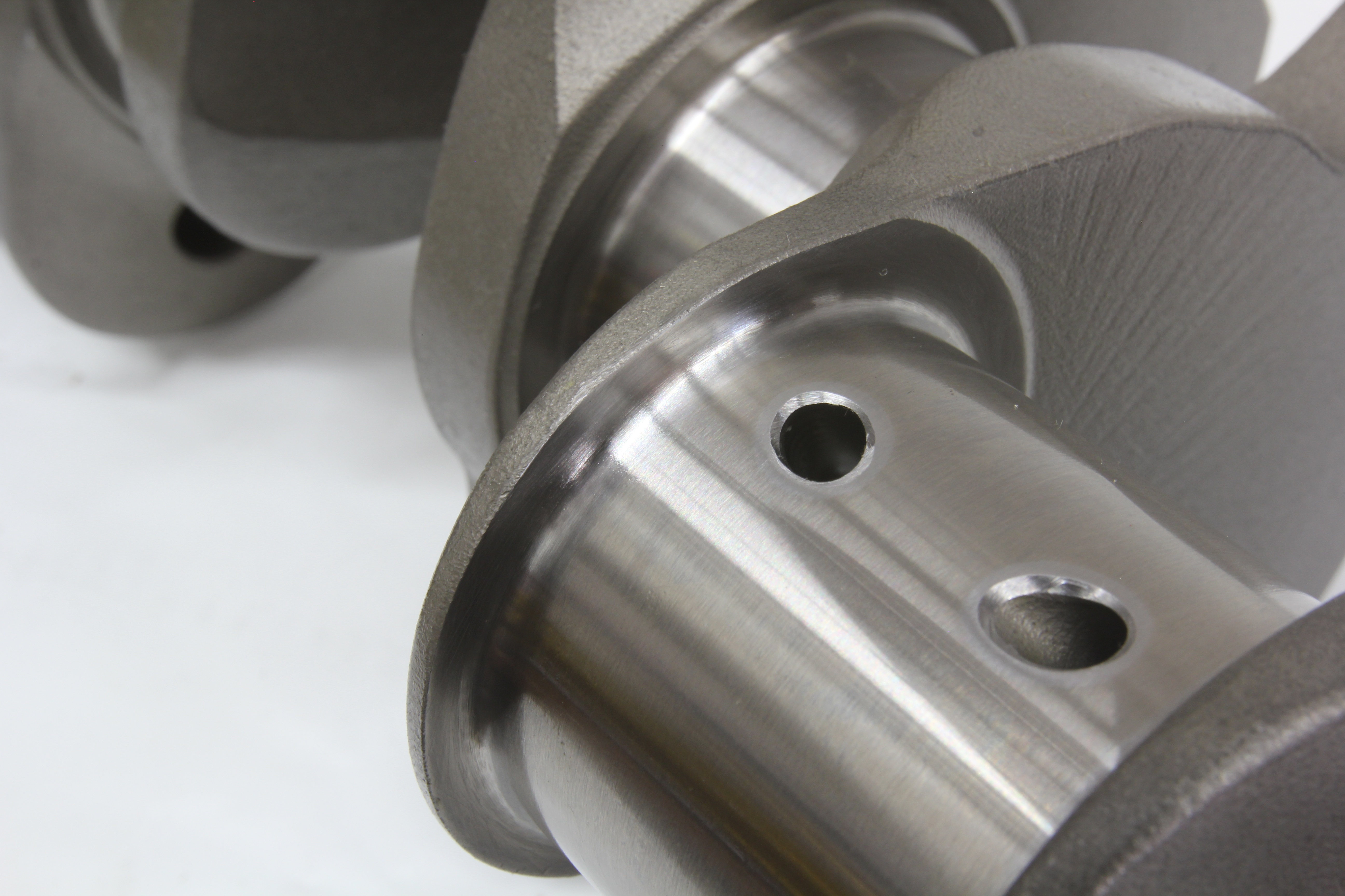
Close-up shows the fillet radius on the crankshaft journal and the bearing chamfer that prevents the bearing from riding against the radius.
Coated rod bearings are particularly desir¬able because of their ability to withstand severe conditions such as detonation, which often pound out and destroy conventional uncoated bearings.
The opposite of this is too little crush where radial pressure from the housing is insufficient to hold the bearing stationary. This allows the bearing to shift in its seat and may even lead to a spun bearing in some cases.
Insufficient crush is generally caused by improperly machined bearing seats, insufficient bolt torque, or poor fitment due to dirt or burrs contaminating the housing bore contact surfaces. Properly machined housing bores are also important for proper heat transfer from the bearing back to the housing bore material. This helps prevent overheating the bearing, which leads to flaking and early failure.
Another common failure mode is fillet ride, a condition seen with many racing crankshafts where the fillet radius is increased to improve strength. If the bearings do not incorporate enough clearance for the fiillet in the form of a suitable chamfer, fillet ride occurs and damage ensues. Manufacturers of high-performance bearings now incorporate a generous chamfer on their racing bearings to eliminate this problem. Nonetheless, every bearing must still be checked and verified.
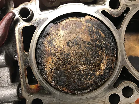
Indications of wiping are also a signal that oiling problems are lurking. This condition often displays a highly polished or worn bearing surface. It is typically caused by insufficient oil pressure and/or oil viscosity or excessive oil temperature. The polishing is generally even across the bearing, but uneven patterns or spots may indicate localized heating due to dirt contamination, bearing misalignment, or possibly an undetected bent rod.
Wiping may not always be severe, but it does indicate the onset of other problems that require attention. Advanced stages of wiping generally indicate oil starvation with the bearing often exhibiting discoloration and very excessive wear. Often this condition is cause by basic problems ranging from insufficient oil clearance to incorrect oil viscosity, blocked oil passages, plugged oil filter, poor sump design, or a partial pump failure.
Clevite advises obtaining oil pressure via cranking prior to ignition switch-on to help extend bearing life because it prevents engine startup until full oil pressure has reached the bearings. This is a good solution, and the use of a racing accumulator to store oil that pressurizes the engines oiling system prior to startup is also advised. The accumulator functions as a pre-oiler.
Many builders also advise preheating the oil supply with a surface heater either on the oil pan itself or on the dry sump storage tank. Heated oil flows to the bearings more quickly to provide immediate startup protection.
Written by John Baechtel and Posted with Permission of CarTechBooks
btw, if you buy an engine you did not assemble and you have the oil pan off,
before you re-install the oil pan, on any reasonably newly rebuilt engine,
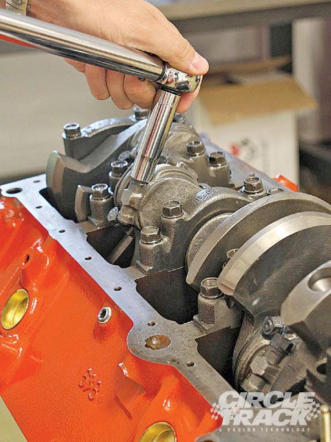
get out your torque wrench and verify the rod bolt torque is consistent,
its not all that rare for someone to forget to go back over the rod bolts torqueing them to a consistent value,
or for a bolt to loosen a bit if it was not properly torqued,
this may prevent future issues you could easily prevent in doing so.
just start tightening a couple and see if they are consistently torqued.
don,t get crazy just verify
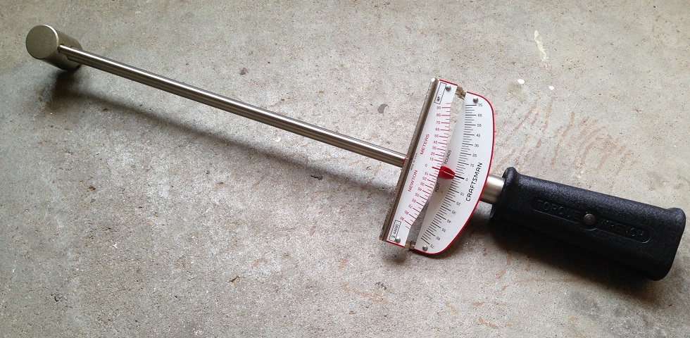
many guys prefer to use a torque beam deflection torque wrench to check that.
you may want to look up the correct torque value for the rods used if you know.
but its likely close to 55 ft lbs, as you check, they should all be consistently torqued to a similar value
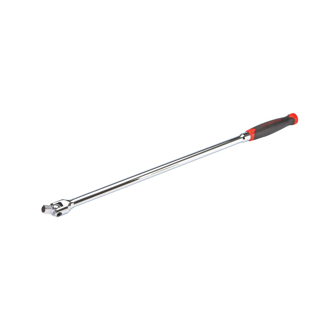
never use a torque wrench as a breaker bar,
BUY A CHEAP BREAKER BAR AND USE IT
Amazing deals on this 1/2In Dr 25In Breaker Bar at Harbor Freight. Quality tools & low prices.

www.harborfreight.com
related threads
(with sub links you also need)
you should read through http://garage.grumpysperformance.co...ng-rod-bolt-stretch-preload.11050/#post-99038
http://garage.grumpysperformance.com/index.php?threads/bearing-clearances.2726/page-2#post-81749
http://garage.grumpysperformance.co...market-4340-connecting-rods.13321/#post-72047
http://garage.grumpysperformance.com/index.php?threads/sbc-spacer-bearings.3058/#post-68193
http://garage.grumpysperformance.com/index.php?threads/rod-bolts-rpm-vs-stress.341/#post-30778
http://garage.grumpysperformance.com/index.php?threads/rod-bolt-mics-stretch-gauges.989/#post-4731
http://garage.grumpysperformance.co...igage-and-checking-clearances.1027/#post-2393
http://garage.grumpysperformance.co...tion-of-crank-durring-short-blk-assembly.852/
http://garage.grumpysperformance.com/index.php?threads/flex-hone.9538/#post-96145
http://garage.grumpysperformance.co...block-cylinder-wall-thickness.976/#post-95567
http://garage.grumpysperformance.co...on-ring-info-youll-need.509/page-2#post-80028
http://garage.grumpysperformance.co...ng-rod-bolt-stretch-preload.11050/#post-99038
http://garage.grumpysperformance.com/index.php?threads/bearing-clearances.2726/page-2#post-81749
http://garage.grumpysperformance.co...market-4340-connecting-rods.13321/#post-72047
http://garage.grumpysperformance.com/index.php?threads/sbc-spacer-bearings.3058/#post-68193
http://garage.grumpysperformance.com/index.php?threads/rod-bolts-rpm-vs-stress.341/#post-30778
http://garage.grumpysperformance.com/index.php?threads/rod-bolt-mics-stretch-gauges.989/#post-4731
http://garage.grumpysperformance.co...igage-and-checking-clearances.1027/#post-2393
http://garage.grumpysperformance.co...tion-of-crank-durring-short-blk-assembly.852/
http://garage.grumpysperformance.com/index.php?threads/flex-hone.9538/#post-96145
http://garage.grumpysperformance.co...block-cylinder-wall-thickness.976/#post-95567
http://garage.grumpysperformance.co...on-ring-info-youll-need.509/page-2#post-80028