Came across this info while doing some research and thought I'd share.
http://www.hobracing.com/tech/tpi_flow.asp
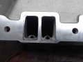
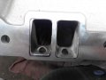
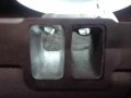
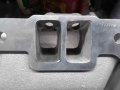
TPI Intakes and runners
The following airflow tests were performed on the University of Northwestern Ohio's SuperFlow SF600 Flow Bench. All CFM values are corrected for airflow at 28 inches of water. Injector flow rates are flowed at 43.5 PSI on an injector flow bench using test fluid with same density as gasoline.
AirFlow
Stock TPI/LT1 48mm Throttle Body w/o airfoil -- 783.0 cfm
Stock TPI/LT1 48mm Throttle Body w/ airfoil -- 821.9 cfm
TPI/LT1 52mm Throttle Body w/o airfoil -- 848.9 cfm
TPI/LT1 52mm Throttle Body w/ airfoil -- 898.8 cfm
Stock 98 Camaro 3800 II Throttle Body -- 554.3 cfm
Stock TPI Bosch MAF sensor w/ screens -- 517.8 cfm
Stock TPI Bosch MAF sensor w/o screens -- 658.4 cfm
Stock 87 GN 3.8L Turbo AC MAF sensor w/ screen -- 584.2 cfm
Stock 86 2.8L AC 5-wire MAF sensor w/ screen -- 576.2 cfm
Stock 96-up AC 3100 V6 MAF sensor w/ screen -- 616.4 cfm
Stock 96-up AC 3100 V6 MAF sensor w/o screen -- 670.7 cfm
Stock 94-up LT1 MAF Sensor w/o screen -- 719.0 cfm
Stock 85-87 Firebird TPI airbox mid piece -- 499.3 cfm
Stock 4.3/5.0/5.7 2bbl TBI complete -- 574.1 cfm (dry)
Stock 4.3/5.0/5.7 2bbl TBI w/o injectors -- 584.7 cfm
Stock 3800 vin L throttle body w/ screen -- 419.1 cfm
Stock 3800 vin L throttle body w/o screen -- 444.8 cfm
4bbl MPFI Holley Throttle Body -- 1287.6 cfm
Another source sent in these flow numbers
Flow and HP ratings for Throttle-bodies:
Flow (cfm) Max. NA HP
Stock 668 300
Stock w/airfoil 710 350
52MM w/airfoil 835 400
54MM (AS&M) 900 450
58MM 1050 500
TPI Intakes and runners flow rates
Stock intake manifold with runner
Stock....................198.72 cfm
ACCEL................213.52 cfm
Extrude/ACCEL....217.11 cfm
Super Ram............220.67 cfm
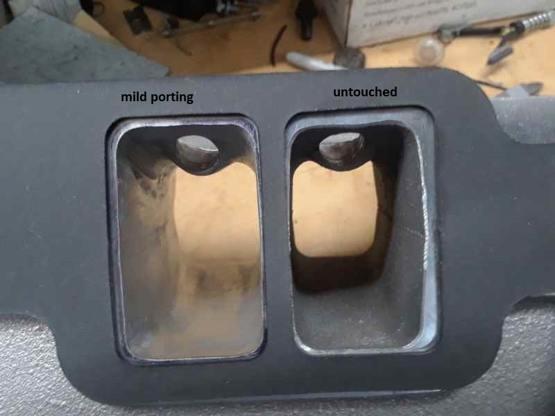
the stock TPI has a hard time flowing 230cfm even with minor port work, look here
most of this info is right off the accel,holley,edelbrock, and TPIS sites, add a little math and the results become much clearer!!!
Intake....... length ....... port in -- out
Stock GM Base--- 6.375"------ 1.47"- 1.96x1.2
TPiS base------ -6.125"------ 1.75"- 2.09x1.28
Accel base----- -6.125"------ 1.75"- 2.09x1.28
Holley base------- 6” runner 2.3”- 1.9”x 1.23 (2.337 sq inches)
Runners
Stock TPI----- -- 7.250"------1.470" round(1.70 sq inchs)
SLP ----------- - 6.625"------1.600" round (2.01 sq inchs)
Accel LTR------- 6.625"------1.615" round (2.05 sq inchs)
TPiS----------- 7.625"------1.660" round (2.168 sq inchs)
Mini ram -----3.5”
LT1 ----------3”
Runners (measured individually)
Stock....................203.17 cfm
ACCEL................242.02 cfm
Extrude/ACCEL...275.83 cfm
Super Ram............289.18 cfm
Intake manifold with 3/8 inch radiused intlet.............................222.45 cfm
Holley stealth ram ………..275cfm
Stock intake manifold with runner
Stock....................198.72 cfm
ACCEL................213.52 cfm
Extrude/ACCEL....217.11 cfm
Super Ram............220.67 cfm
Holley stealth ram …..275cfm
ACCEL Hi-Flow intake manifold with 3/8 inch radiused inlet.........251.51 cfm
ACCEL Hi-Flow intake manifold with runner
Stock....................215.83 cfm
ACCEL................232.53 cfm
Extrude/ACCEL....243.21 cfm
Super Ram............240.24 cfm
Extrude-Honed ACCEL Hi-Flow intake manifold with 3/8 inch radiused inlet ...............275.83 cfm
Extrude-Honed ACCEL Hi-Flow intake manifold with ACCEL runner ..............266.94 cfm
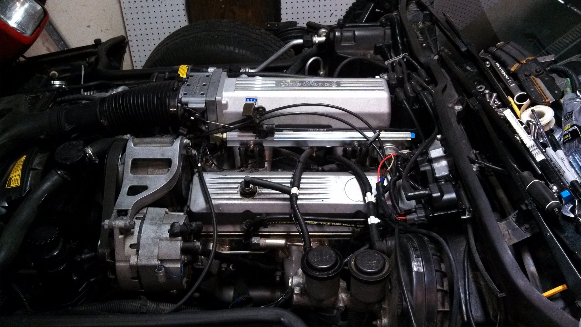
Edelbrock Performer RPM manifold (Stock)..........286.51 cfm
Edelbrock Victor Jr. ............275.24 cfm
HOLLEY STEALTH RAM
the HOLLEY STEALTH RAM FLOWS at 275cfm out of the box, and has the potential when matched to the correct heads and cam to totally out flow most other intakes available,can easily reach 300cfm with minor port work and costs much less
Stock…………………………… 275cfm
Ported…………………………..300cfm
Runner lengths
Stock tpi manifold 8” runners 11.25”, cylinder head 6” total 25.25”
Accel super ram manifold 8” runners 7” cylinder head 6” total 21”
Holley stealth ram manifold 6.26” ” cylinder head 6” total 12.26”
Edelbrock performer RPM runners 6” ” cylinder head 6” total 12”
Edelbrock vic jr , runner length 5.5” ” ” cylinder head 6” total 11.5”
Also interesting TPI mods. Not so sure I agree with the one on bumping up the initial timing.
http://www.hobracing.com/tech/tpi_mods.asp
Basic TPI modifications
Friday, May 23, 2014
READ THIS