1984 crossfire vette won,t run right?

grumpyvette

Administrator
Staff member
Oneslyfox1981 said:
I have a 84 crossfire injection corvette I set the timing and it misses horribly if I advance the timing it idles high but takes gas better but still misses and stalls the computer throws code 51 I have two ECMs I've tried and two different chips still same problem and same code
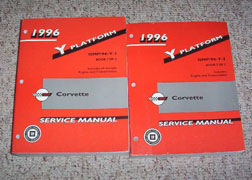
BUY A SHOP MANUAL
51ciVS1FMKL._SX383_BO1,204,203,200_.jpg


http://www.technovelocity.com/chevyhack ... olish.html
Code #12: Normal System No Codes.
Code #13: Oxygen Sensor Circuit:
Code #14: Coolant Sensor Circuit Low.
Code #15: Coolant Sensor Circuit High.
Code #21: Throttle Position Sensor High.
Code #22: Throttle Position Sensor Low
Code #24: Vehicle Speed Sensor.
Code #33: Manifold Absolute Pressure Sensor Signal High.
Code #34: Manifold Absolute Pressure Sensor Signal Low
Code #42: Electronic Spark Timing.
Code #43: Electronic Spark Control..
Code #44: Lean Exhaust Indication.
Code #45: Rich Exhaust Indication.
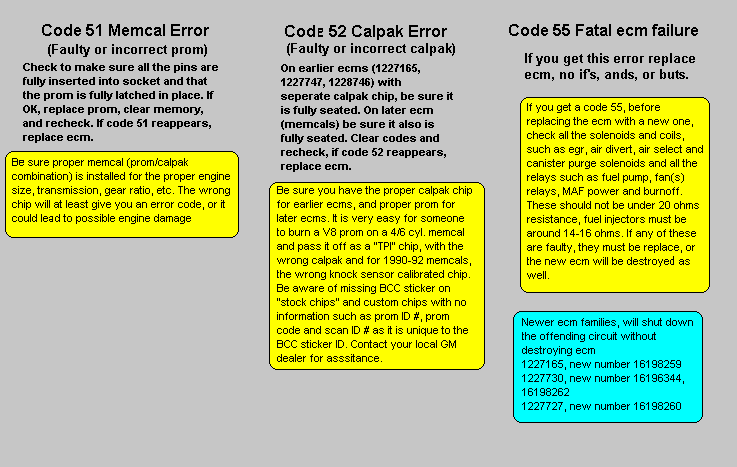
Code #51: PROM Error.
Code #55: Defective ECM.
without testing and verifying what your dealing with your guessing as to the cause,while you might be dealing with a defective chip or loose electrical contact, or broken wire it could also be related to a defective sensor, you really need a SHOP MANUAL, matching your year corvette, not an auto parts store chilton or similar reference book,the chances are very good that either the outer damper ring is loose and the timing marks no longer indicate TRUE TDC or
THAT YOUR TIMING CHAIN HAS A GOOD DEAL OF SLACK, OR MAYBE THE CAM HAS A WORN LOBE,the first thing Id suggest is verifying both TDC on the damper and true TDC match,and testing your fuel pressure, would help.
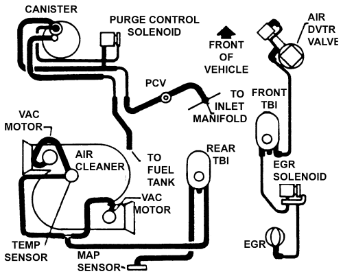
verify the ignition advance and veriify your timing,check for loose or rotten vacuum lines and loose electrical connectors and adjusting your valves and doing a compression check sure would be useful in determining your problems source
remember the shop manual for your year corvette remember you'll YOULL want to read the shop manual for instructions for specific. info that applies, to your car and year
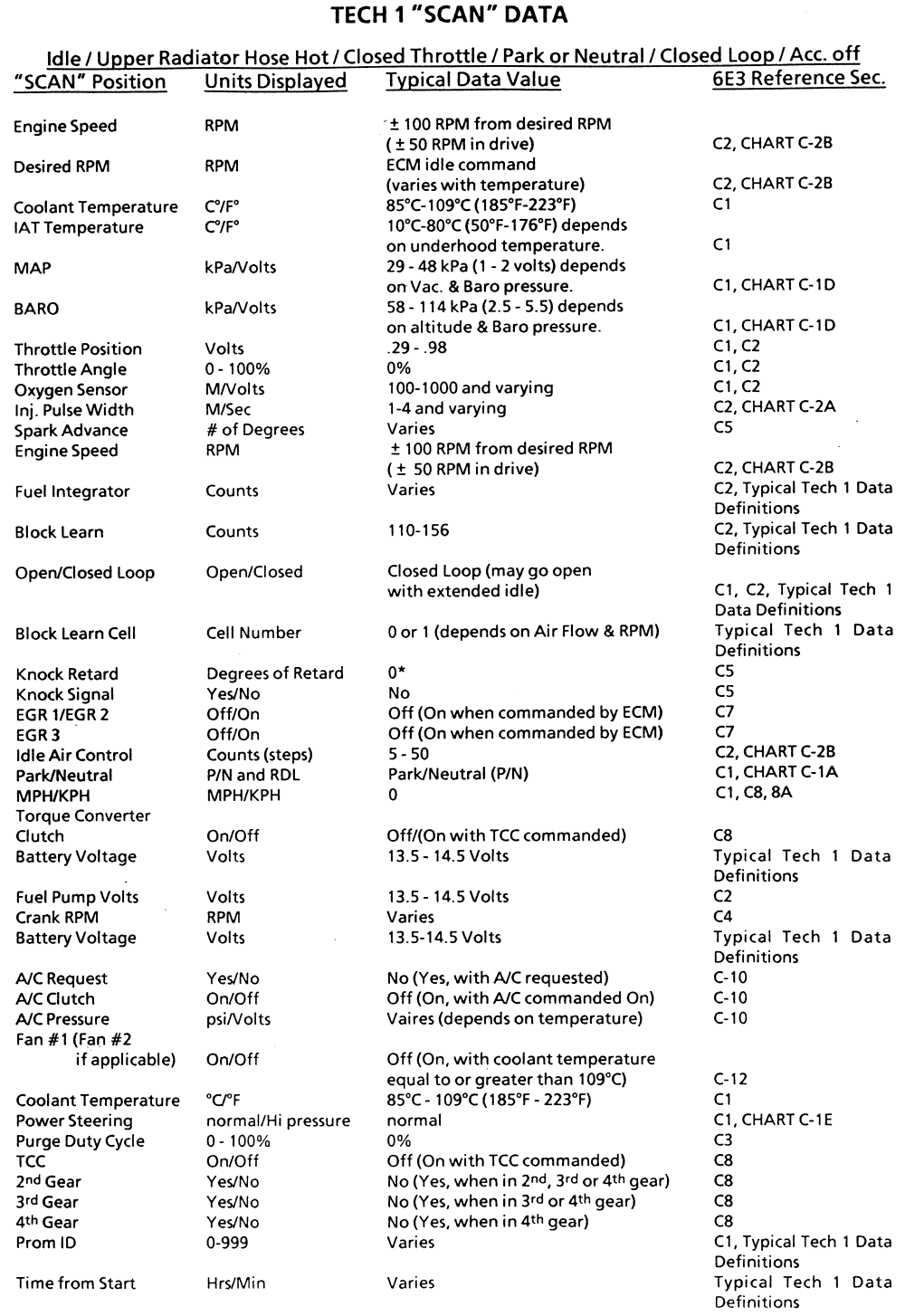
1984data.gif

1984: ECM Codes
Code #12: Normal System No Codes.
Code #13: Oxygen Sensor Circuit.
Code #14: Coolant Sensor Circuit Low.
Code #15: Coolant Sensor Circuit High.
Code #21: Throttle Position Sensor High.
Code #22: Throttle Position Sensor Low.
Code #24: Vehicle Speed Sensor.
Code #33: Manifold Absolute Pressure Sensor Signal High.
Code #34: Manifold Absolute Pressure Sensor Signal Low.
Code #42: Electronic Spark Timing.
Code #43: Electronic Spark Control.
Code #44: Lean Exhaust Indication.
Code #45: Rich Exhaust Indication.
Code #51: PROM Error.
Code #55: Defective ECM.
Code_515255.gif

CROSSFIRE
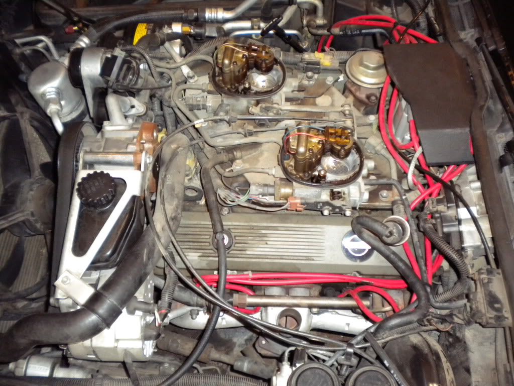
crossfire1.jpg


2010-04-07_152249_vette.gif


will this help?
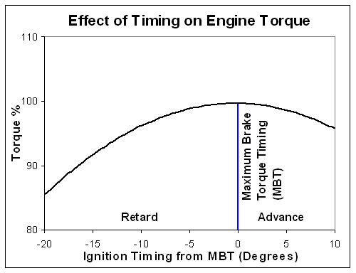
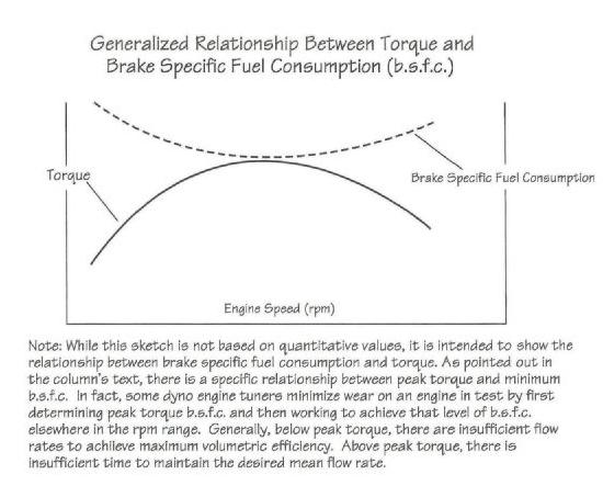
Timing_Torque.gif

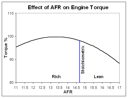
AFR_Torque.gif

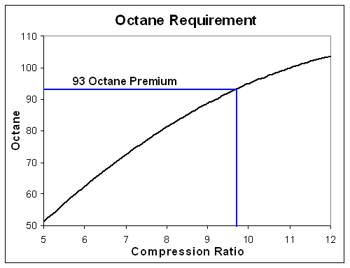
Octane_Requirement.gif

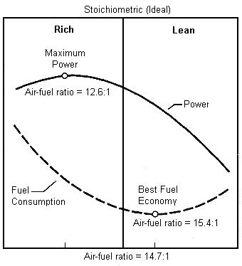
Stoich.gif

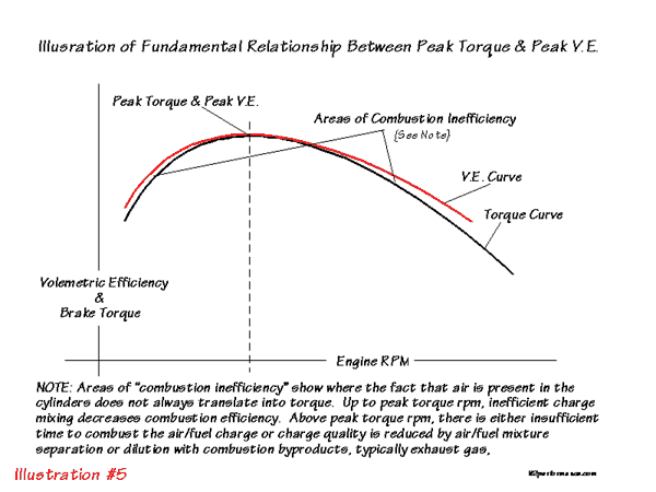
volumetricz.jpg

volumetric.gif

https://www.corvettemods.com/C3-C4-...ke-Manifold--Crossfire-Injection_p_14318.html
rensale.png

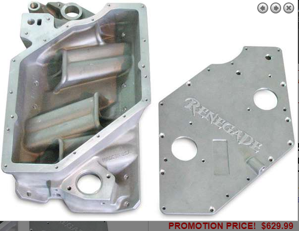
if your thinking of buying a renegade intake upgrade here is a damn impressive limited time sale

this infos bound to be helpful at times
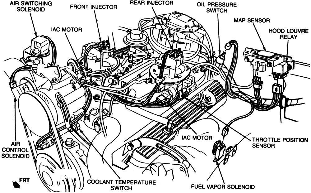
Sensor Locations

Sensor
Location

Engine Coolant Temperature Sensor. Front of engine, below Throttle Body.
Engine Oil Temperature Sensor. Left rear of engine, just above the oil filter.
Oil Pressure Sender/Switch. Top, left hand rear of engine.
Fuel Quantity Sender. Top of fuel tank, beneath filler pipe escutcheon panel.
MAT (Manifold Absolute Temperature Sensor). Underside of manifold air plenum at rear.
Outside Temperature Sensor. Right side of engine, top right corner of radiator.
In Car Temp Temperature Sensor. Coupe: above left seat near interior courtesy light, Convertible: center of cargo compartment lid.
MAF (Mass Air Flow) Sensor. Front of engine ahead of throttle body.
Oxygen (O2) Sensor. Left side of engine, in exhaust pipe.
TPS (Throttle Position Sensor). Right side of throttle body at the front.


Sensor Outputs:

Sensor
Measured Value

Engine Coolant Temperature Sensor. 185 Ohms @ 210F, 3400 Ohms @ 68F, 7,500 Ohms @ 39 F.
Engine Oil Temperature Sensor. 185 Ohms @ 210 F, 3400 Ohms @ 68 F, 7,500 Ohms @39 F.
Oil Pressure Sender/Switch. 1 Ohms @ 0 PSI, 43 Ohms @ 30 PSI, 86 Ohms @ 60 PSI.
Fuel Quantity Sender. 0 Ohms @ Empty, 45 Ohms @ 1/2 Full, 90 Ohms @ Full.
MAT (Manifold Absolute Temperature Sensor). 185 Ohms @ 210 F, 3400 Ohms @ 70 F, 15,000 Ohms @ 40 F.
Outside Temperature Sensor. 4400 Ohms @ 60 F, 2200 Ohms @ 85 F.
In Car Temp Temperature Sensor. 4400 Ohms @ 60 F, 2200 Ohms @ 85 F.
MAF (Mass Air Flow) Sensor. .4 Volts @ idle, 5 Volts @ Full Throttle.
Oxygen (O2) Sensor. .1 Volt Lean Mixture, .9 Volt Rich Mixture.
TPS (Throttle Position Sensor). .54 Volts Idle, ~ 5 Volts Full Throttle.
user_online.gif


RELATED INFO THAT MIGHT HELP


http://www.thecubestudio.com/CrossfireT ... sIndex.htm


http://garage.grumpysperformance.com/index.php?threads/got-a-cross-fire-corvette.640/#post-25767

 
Last edited by a moderator:
Re: 84 vette won,t run right?

toobroketoretire said:
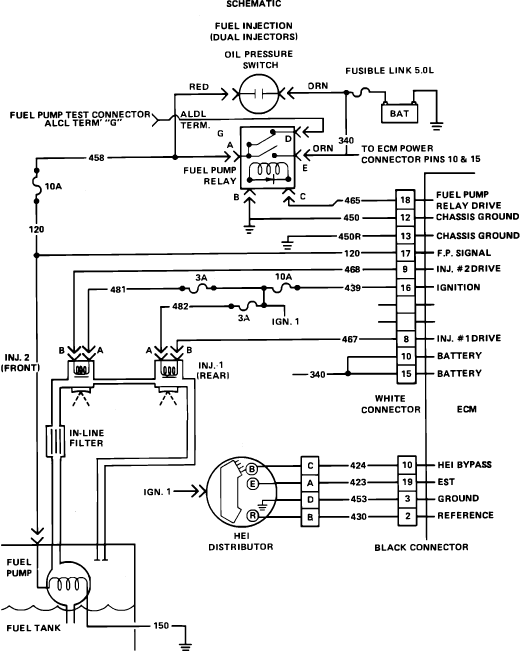
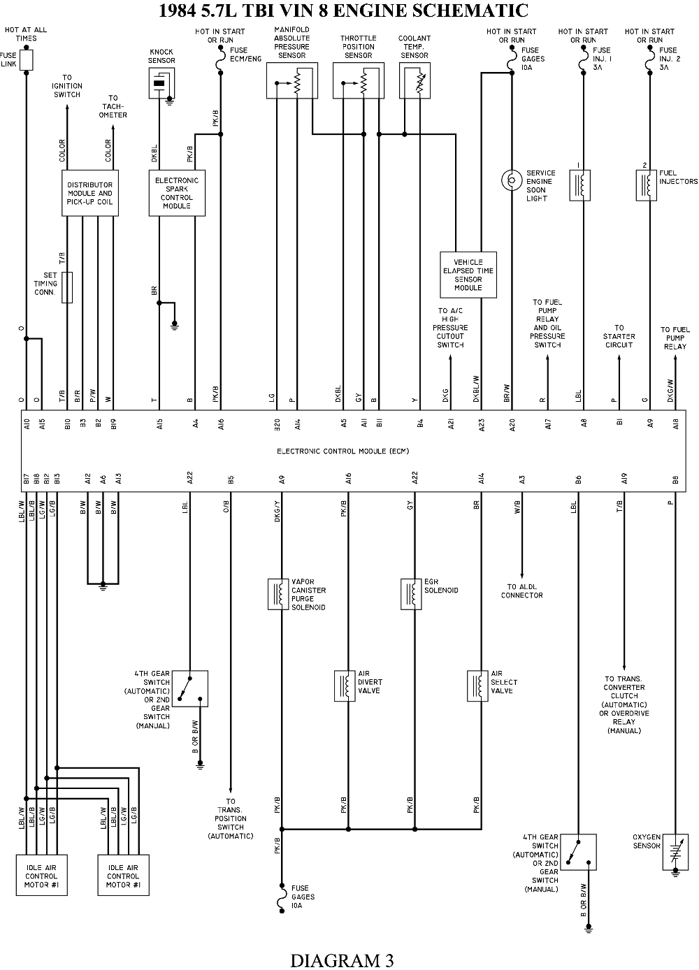
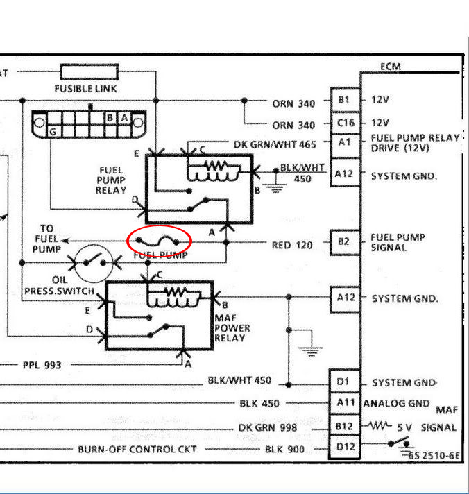
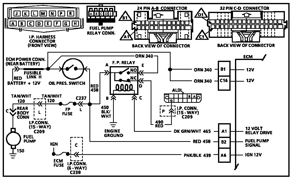
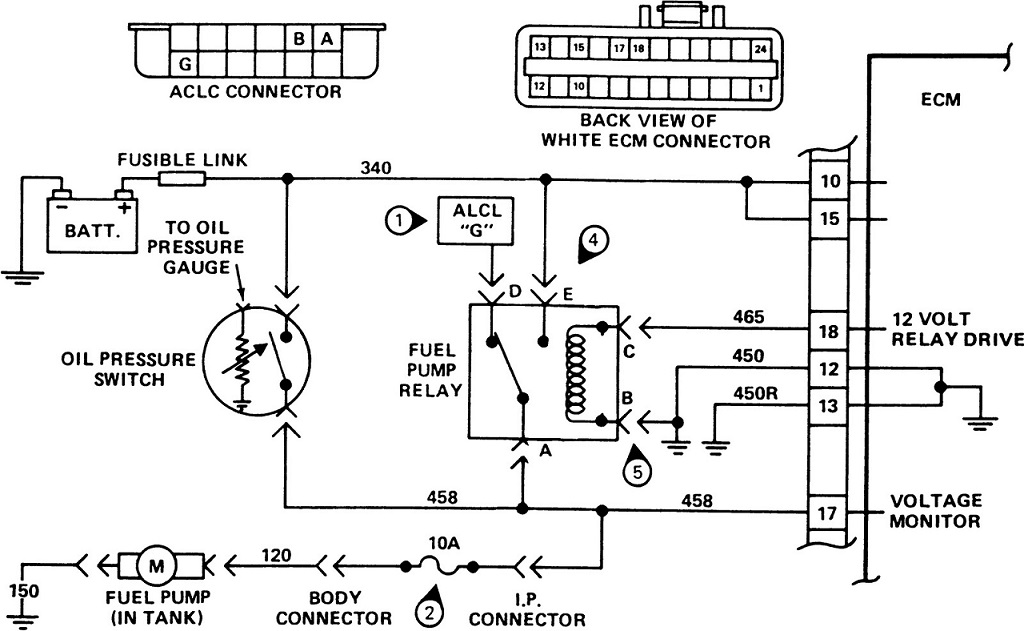
I can tell you most anything you would ever want to know about the Crossfire Injected engine. For starters there is a temperature sensor that is screwed into the front of the intake manifold about 3" to the right of center. That sensor gives the computer the coolant temperature needed to adjust the air/fuel mixture for cold starts. Then on the firewall behind the power brake unit is your MAP sensor. The MAP sensor reads manifold vacuum and sends that information to the computer. Also there is a throttle position switch (TPS) mounted on the left side of the left throttle body. That TPS gives the computer the amount of throttle opening and should be adjusted to .525 volts. Then there is a O2 sensor just ahead of your catalytic converter and that tells the computer how rich or lean your fuel mixture is. As your engine is "fuel injected" you always start it with a closed throttle. The computer will automatically make your engine fast idle when the coolant temperature is low and will gradually slow the engine down as it warms up. There is a 25 micron fuel filter in the inlet line and it's mounted on the right side frame rail right under the passenger's feet. Your electric fuel pump is mounted inside the fuel tank and it will only run for 2 seconds when you turn your key on unless your oil pressure switch reads 5 psi or more pressure. If the pressure is there the fuel pump will continue to run."
READ THRU THESE LINKS CAREFULLY
http://www.secondchancegarage.com/public/186.cfm

viewtopic.php?f=32&t=1401&p=39419&hilit=manual+meter+shop#p39419

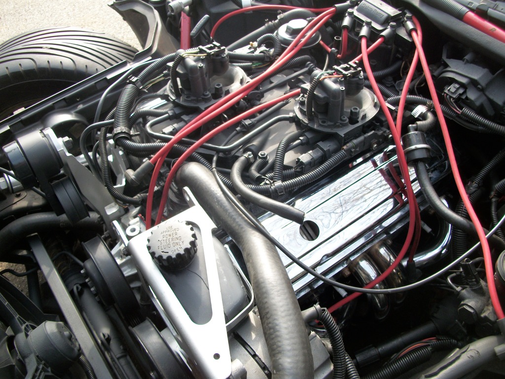
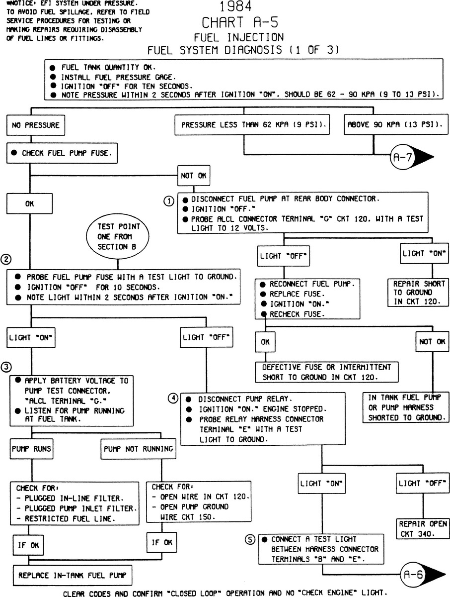
youll want to figure out if your dealing with an ignition related, like the ignition timing is wrong or your not getting a spark or the ignition is not advancing consistently as the rpms increase, or fuel delivery issue, like a lack of fuel pressure (you should see 12psi-14psi on a cross fire TBI system) or volume or a mechanical issue like compression or loss of oil pressure,OR a sensor issue like an O2 or heat sensor giving the CPU error data., or a plugged exhaust, like a catalytic converter thats melted, partly closed as a first step in diagnosing any issue with the car not running correctly.
obviously doing basic testing helps,
so start with a compression test, all cylinders should read within 10%
Id get out a timing light and verify TDC on the damper and then set the timing and check for a consistently smooth advance on the ignition, Id pull and inspect the distributor cap and rotor carefully.
get out a fuel pressure gauge and verify your getting consistent fuel pressure
Id sure use a basic pressure test on the exhaust to verify the catalytic converter was not restrictive, and Id change the fuel filter out if its over 3 month old.
obviously pull trouble codes, check all fuses and sensors. and you darn sure need the factory shop manual for your year corvette.


http://www.helminc.com/helm

1996_Corvette.jpg

image_6238.jpg

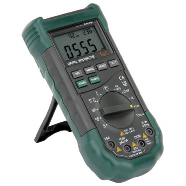
http://www.harborfreight.com/5-in-1-dig ... 98674.html
LOTS OF RELATED INFO IN THESE LINKs
viewtopic.php?f=50&t=9478&p=34812&hilit=noid#p34812

viewtopic.php?f=80&t=728&p=9217&hilit=sensors+camaro#p9217

viewtopic.php?f=70&t=7309&p=24862&hilit=meter+manual+gauge#p24862

http://chevythunder.com/cross_fire_inje ... 821984.htm

http://chevythunder.com/ignition_system ... ration.htm

1984vc1.gif


1984vc2.gif


1984c2.jpg

82crossfire.gif
 
Last edited by a moderator:
http://www.thecubestudio.com/CrossfireT ... sIndex.htm

http://www.thecubestudio.com/CrossfireT ... ancing.htm

http://www.technovelocity.com/chevyhack ... olish.html
http://garage.grumpysperformance.com/index.php?threads/got-a-cross-fire-corvette.640/#post-50502


http://garage.grumpysperformance.com/index.php?threads/ported-crossfire-383.10240/#post-41000

http://garage.grumpysperformance.com/index.php?threads/a-few-cross-fire-tips.303/#post-987

http://garage.grumpysperformance.com/index.php?threads/renegade-intake-for-cross-fires.2796/

http://garage.grumpysperformance.com/index.php?threads/1984-corvette-questions.4918/#post-13583

http://garage.grumpysperformance.com/index.php?threads/1984-crossfire-vette-won-t-run-right.10096/

http://garage.grumpysperformance.com/index.php?threads/bits-of-crossfire-info.1148/#post-2333

http://garage.grumpysperformance.com/index.php?threads/a-few-cross-fire-tips.303/#post-986

the stock 1984 cross fire cylinder heads are pathetically restrictive
more info
just a bit of info on those stock #624 head flow rates

.......intake....exhaust
.100..44..........41cfm
.200..101..........82cfm
.300.155..........125cfm
.400..182..........137cfm
.500..196..........140cfm
READ THRU THE LINKED INFO ABOVE
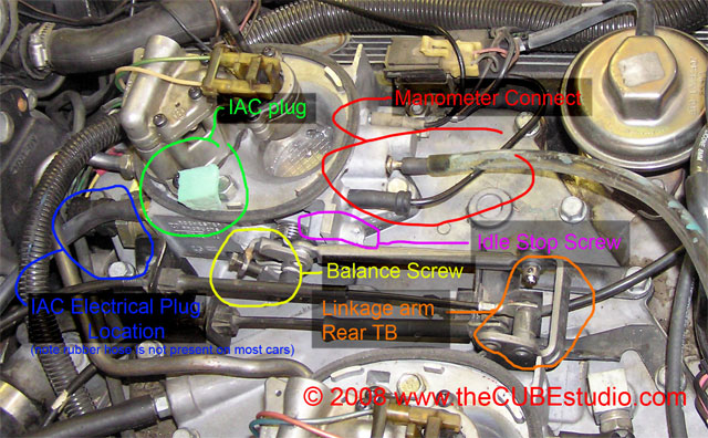
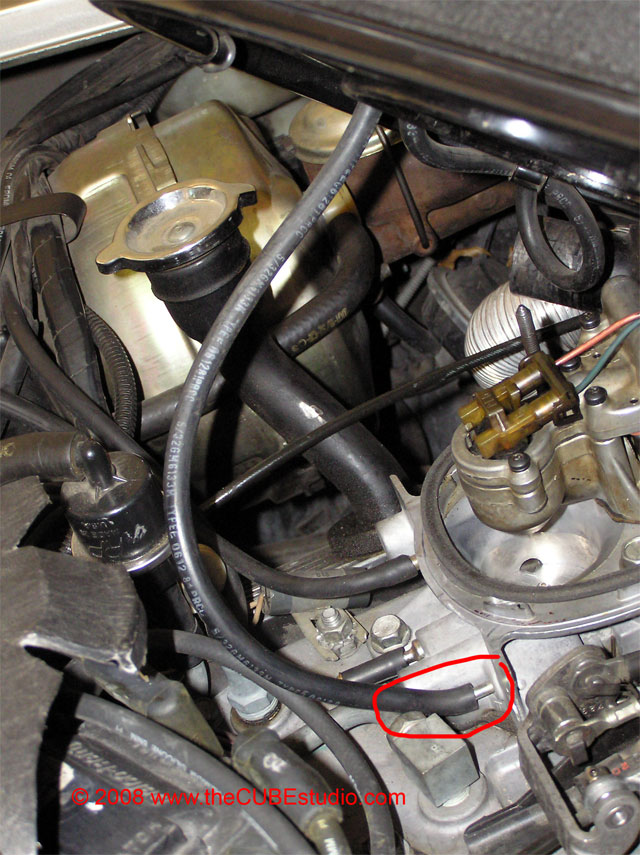
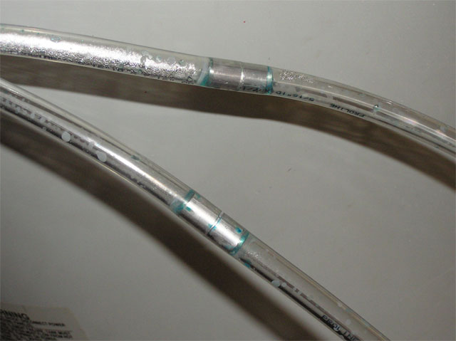
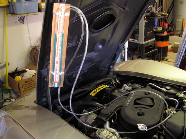
you can easily fabricate a custom built MANOMETER (fancy word for a tool that allows you to balance and equalize the flow rates of the two throttle bodys on the cross fire intake manifold

STEP ONE


Shopping


Hit the local hardware store and buy 12 feet or so of 5/16” or 3/8” clear vinyl tubing. There are some photos circulating the web of a home made manometer using very thin tubing . like maybe 1/8”. If you are considering this, slap yourself or poke yourself in the eye with a sharp stick . . because that will be less painful that trying to get the bubbles out of 1/8” tubing.


Get some nylon clips to hold the tubing . . . if you are an actual genuine red-neck, you may use strips of duct tape or bent over rusty nails. For a classy read-neck manometer, splurge and get a get a $1 yardstick. Here again black marks every inch is all you really need, but the yardstick is in the budget, so go ahead, get crazy.

You need two one inch long pieces of vacuum hose . . you can buy new or snip some from your vacuum gage or from under your hood somewhere.

Some food coloring is nice, but not required. BTW, the term ‘food’ actually means “food, clothing, hands, garage floor, car body, dog and anything else nearby” coloring.

Now the tricky part is finding special ‘manometer wood’. This is rare stuff not usually available at any store. Fortunately it can often be found propped up in the corner of the average garage, origin unknown, age unknown. It comes in various sizes and is easily recognized by the brown color.

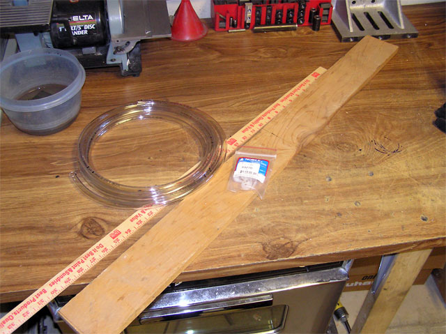
Shopping expedition should yield a bootay pile similar to this:

mano1.jpg

STEP TWO


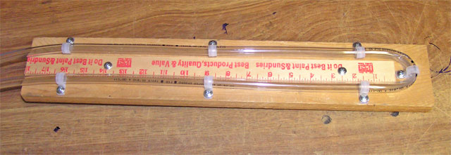
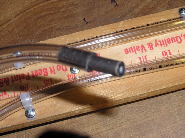
Build the manometer. (i.e. arrange the bootay like so:)

mano2.jpg

STEP THREE


Stick the vacuum tubing into the ends of the vinyl

mano3.jpg


Hardly deserves its own step . . . OK, we’ll do the hanger too:


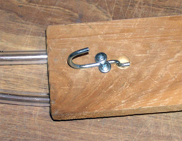
In keeping with the overall red-neck theme .. concoct some form of hanger. Here we see the recycled peg board hanger method.
mano4.jpg


OPTIONAL STEP


Your water manometer is exactly as accurate as anything you can buy. It is also very . . . responsive, shall we say. If you hook your manometer up to the port when it is pulling a lot of vacuum, you have .001 seconds to disconnect it before the water goes bye-bye. Don’t worry about it if it happens, It will not hurt the engine at all.


You can install restrictors in the line to dampen the response of the manometer without changing the accuracy. Any small orifice will do and it actually only has to be in one leg. I used a piece of aluminum rod with a 1/16” hole drilled thru it. I later discovered that a very small plastic wall anchor stuck into one of the pieces of vacuum tubing works almost as well.

mano5.jpg

And Viola! (that’s French for Gosh Dern!) You now have a working manometer!


STEP FOUR


Just add water.


You can mix up some food coloring in a bowl . . dip one end ogf the manometer tube in the water and suck on the other end until you get about half the manometer’s height in water sucked in. Remove the end from the bowl and hold both ends up high and the manometer will fill up nicely . . .


Perform a quality control test of the hanger mechanism:
mano6.jpg


mano7.jpg

mano8.jpg

mano9.jpg

mano10.jpg

mano11.jpg

STEP FIVE


Making companion tools
11-14 psi is generally what you see on the cross fire c4 corvette
https://www.restore-an-old-car.com/corvette-crossfire-engine.html

http://garage.grumpysperformance.co...sfire-vette-won-t-run-right.10096/#post-39710


1984fim3.jpg

1984fim4.gif

1984fim5.jpg


1984fim1.jpg


1984fim2.jpeg

1984fim1.jpg

1984fim2.jpeg


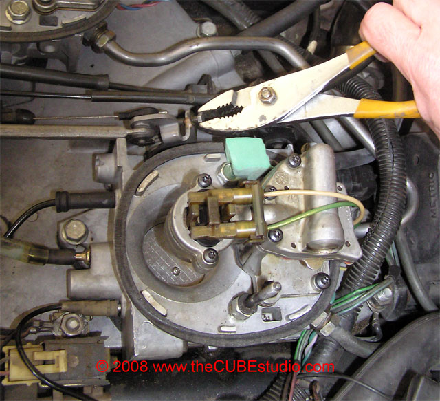
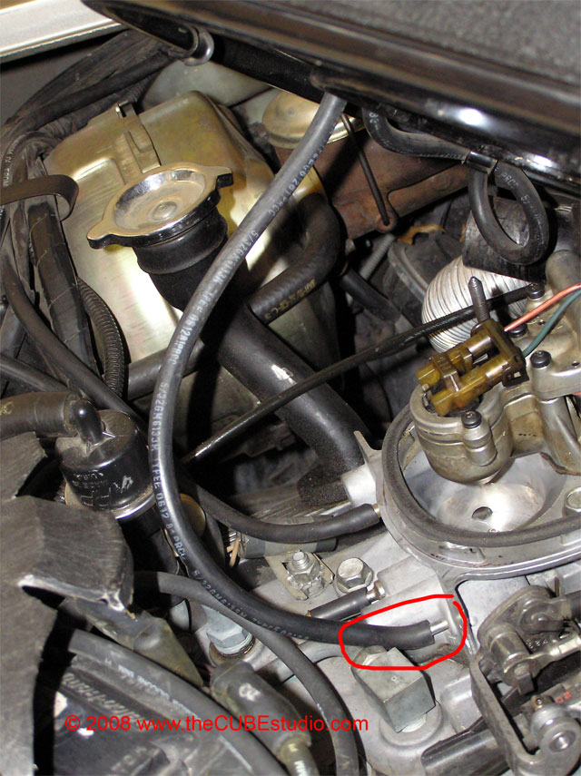
You will need a tool to block the IAC passage. This can be a special GM tool number J- dash - blah blah blah:
 
Last edited by a moderator:
Back
Top