yes IM well aware theres a great deal of links with info you need to read that you'll most likely skip over,.....
theres a great deal of additional info in the links and sub-links posted in the thread below.when you find you've got questions or just want to fully understand the process reading the links provides you with the required info, so ID strongly suggest taking the time to read thru them, as you'll be amazed at what they contain.
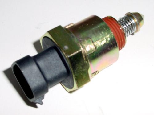
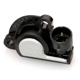
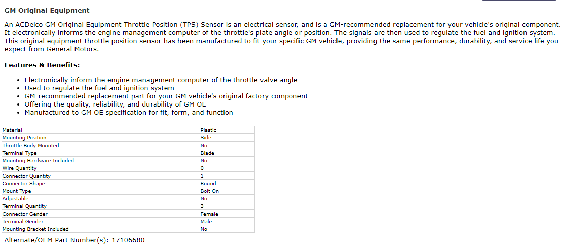
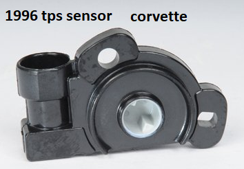
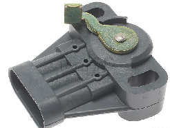
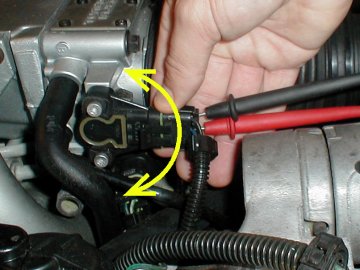
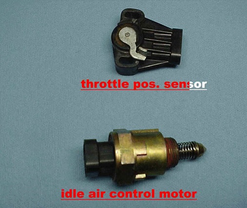
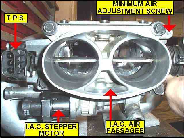
the prime symptoms of a defective IAC is an engine that either won,t idle at a consistent RPM,or it won,t keep running, or it just changes speeds and won,t settle down almost like a vacume leak, a defective or badly adjusted or defective TPS tends to result in a loss of engine response and either fouled plugs or plugs showing excessively lean combustion.
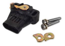
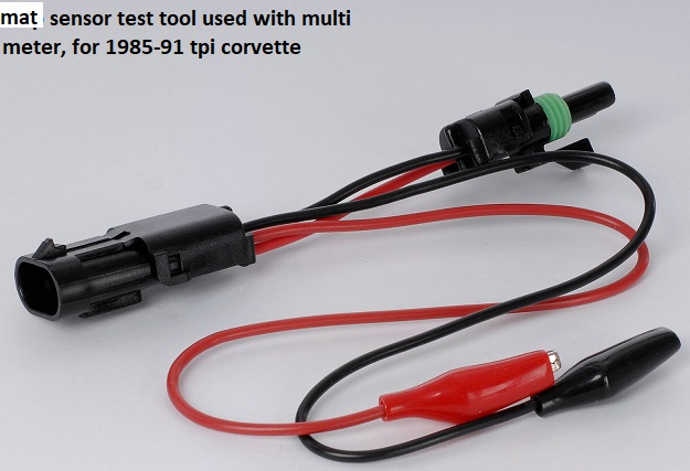
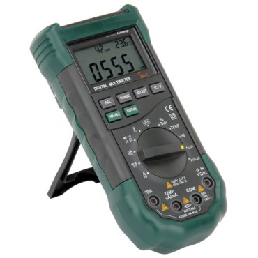
the TPS is easily checked with a multi meter, the IAC can be removed and cleaned, as will the throttle body its installed in, but these do go bad and need replacing
If your trying to isolate and test and get the engine tune correct, on any efi system,
Id suggest you leave the fuel pressure alone if its at least 40 psi and does not exceed about 58 psi,
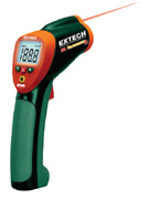
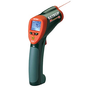
and if the fuel pressures consistent, and set the spark plug gap at .043-.045 max and keep th engine coolant temps as consistent and near about 180F-190F as you can get them,
the fewer variable your forced to deal with the better, make the changes in INJECTOR PULSE DURATION and ignition advance curves
to vary the fuel/air ratios and cylinder pressure
to avoid detonation and tuning issues
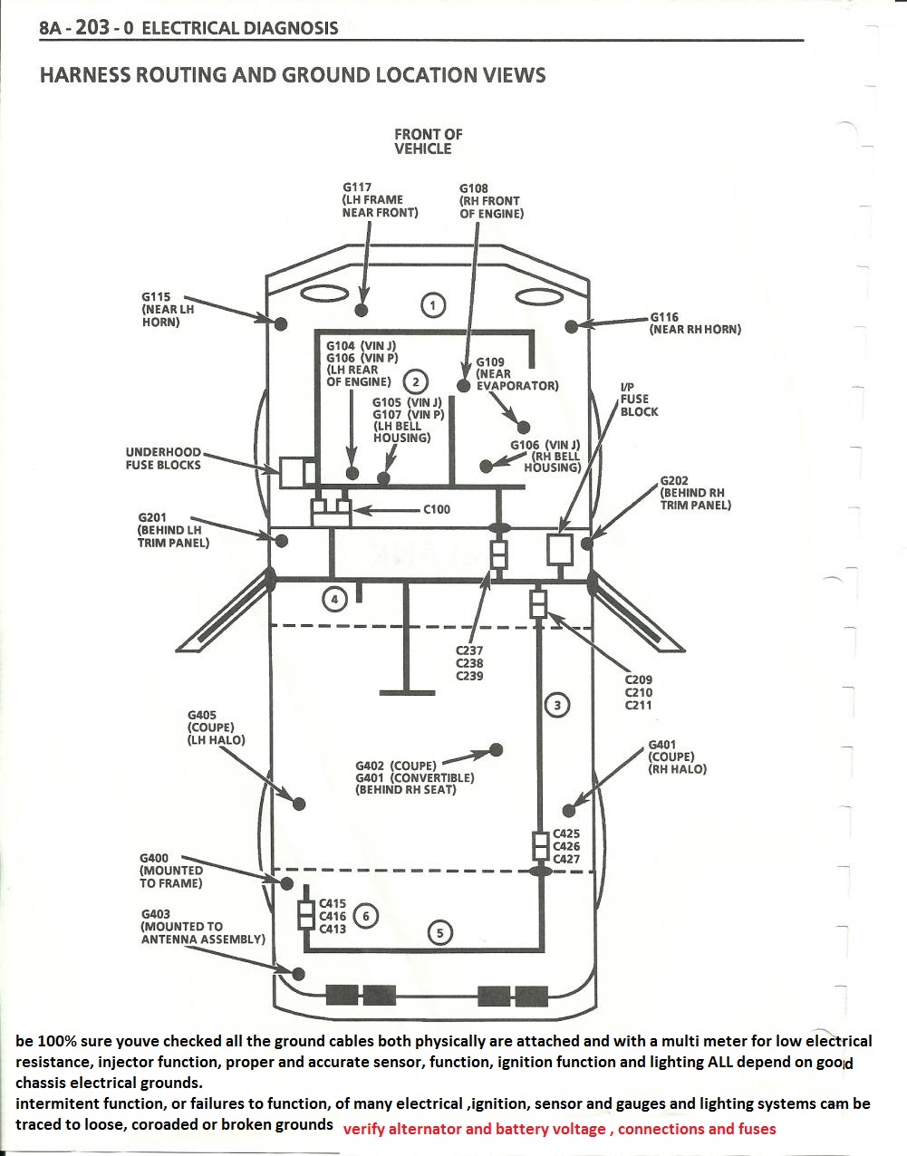
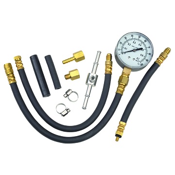
always start by verifying what your dealing with in temps fuel pressure and sensor function, pull trouble codes and read and tuning instructions, get a shop manual and verify sensor functions and electrical connections electrical grounds, ignition firing orders, do a compression test and verify the valve lash, set the valves if that's required, and make sure your not dealing with partially clogged catalytic converter carefully, verify what your dealing with, don,t guess, verify.
I can assure you that most problems are related to guessing or defective sensors, or assuming somethings working, that you fail to verify, like the ohms resistance in ignition wire or the firing order or verifying TDC, vs the damper/timing tabs
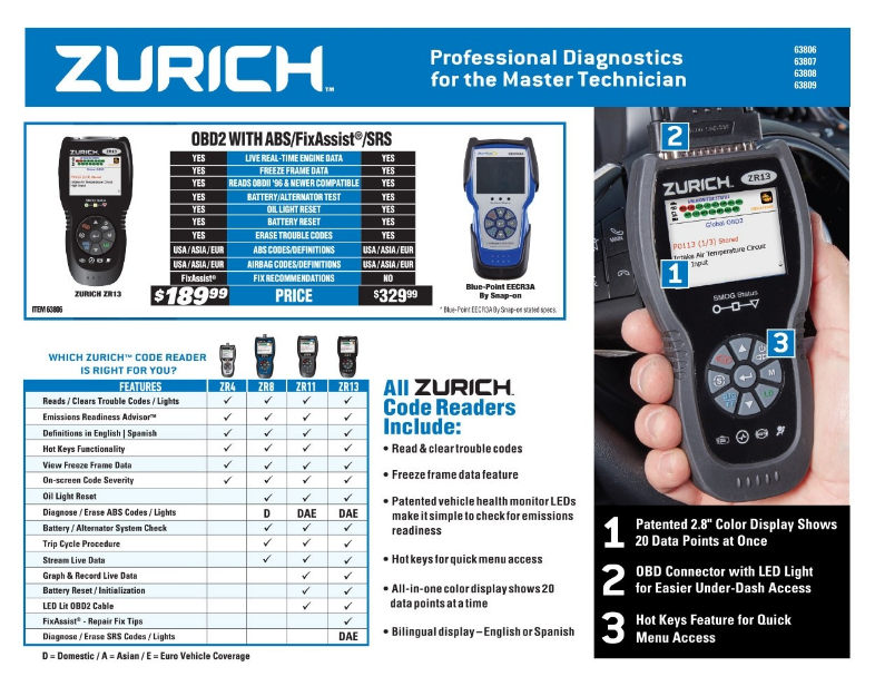
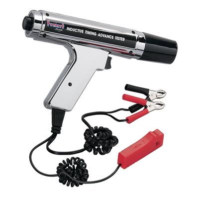
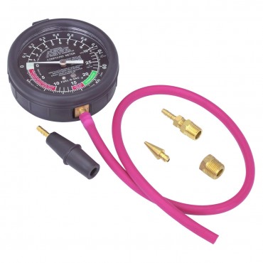
having a set of multi meter/timing light, compression gauge, vacuum and fuel pressure gauges and a shop manual is critical.
SKIPPING OR NOT READING LINKED INFO ON THIS WEB SITE IS ALWAYS A BAD IDEA
http://repairs.willcoxcorvette.com/1985-1989-corvette-idle-to-air-mixture-adjustment-procedure/
http://garage.grumpysperformance.co...-cranks-but-won-t-start-intermittently.14212/
http://garage.grumpysperformance.com/index.php?threads/throttle-body-coolant-bye-pass.169/#post-1675
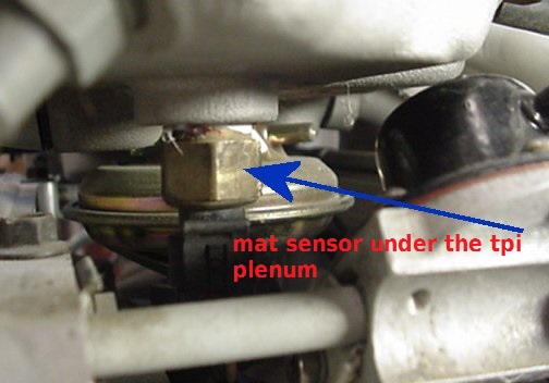
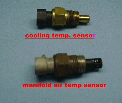
http://garage.grumpysperformance.co...at-manifold-air-temp-sensor.10349/#post-42530
http://garage.grumpysperformance.co...rottle-body-size-52mm-vs-58mm.641/#post-26207
http://garage.grumpysperformance.com/index.php?threads/adjusting-your-tps-and-iac.168/#post-202
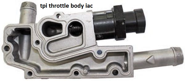
removing the coolant passage that provides hot engine coolant to heat the throttle body from the throttle body, is ok, but don,t remove the IAC sensor
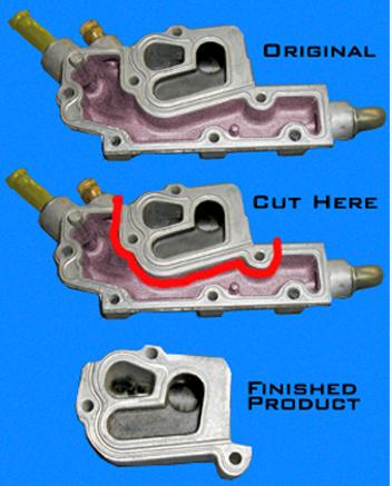
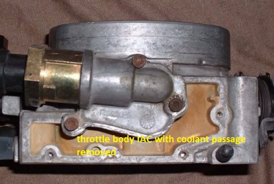
keep in mind with some aftermarket efi intakes the throttle body coolant component of the IAC throttle body housing must be removed to allow the t-stat housing to fit
Start and run engine until it reaches operating temperature (closed loop)
Check and set ignition timing to 6 degrees before dead center (BDC) with tan EST wire disconnected
Check and set throttle position sensor (TPS) to .54 (+/- .08) volts at idle
Jumper terminals "A" and "B" on the ALDL
Turn ignition key on and do not start engine
Wait 60 seconds so that the idle air control (IAC) motor fully extends
Without turning ignition key off, remove connector from IAC motor
Turn ignition key off and disconnect ALDL jumper
Attach external RPM meter using Tach port or scanner using ALDL port
Start and run engine until it reaches operating temperature (closed loop)
Remove minimum idle air cap using awl if required
Adjust idle speed to 425 (+/- 25) rpm in either in park or neutral
Turn ignition key off and reconnect EST wire and IAC motor
Check and set throttle position sensor (TPS) to .54 (+/- .08) volts at idle
Reset ECM by disconnecting and reconnecting power at battery terminal
Depress accelerator pedal slightly
Start and run engine for 5 seconds
Turn ignition key off for 10 seconds
Drive vehicle to assist in ECM reprogramming
If you used a scanner, you should see around 20 IAC steps
http://www.ecklerscorvette.com/corvette-idle-air-control-tool-sensor-test-1985-1993.html
I found these bits of linked info that may be useful.
YES THERE'S SEVERAL SUB LINKS
(IN MOST OF THE THREADS)
THEY ALL CONTAIN A BIT DIFFERENT RELATED INFO YOU'LL NEED
ANYTIME YOUR DEALING WITH THE ENGINE AND HOW IT RUNS ,
YOULL BE DEALING WITH DIFFERENT ISSUES,
COOLANT AND OIL TEMPS,& PRESSURE
FUEL PRESSURE , INJECTOR FUNCTION
FUEL DELIVERY, PRESSURE & VOLUME
RELATED FUEL / AIR RATIO
EFFECTIVE COMPRESSION & RING SEAL
VALVE TIMING & LIFT & DURATION & VALVE SEAL
IGNITION SPARK TIMING & STRENGTH, & IGNITION ADVANCE CURVE
EXHAUST BACK PRESSURE
SENSOR OUTPUT TO THE CPU
VOLTAGE & GROUNDS
http://www.thirdgen.org/tpimod2
http://www.batee.com/corvette/dcrg/read ... s_sim5.htm
viewtopic.php?f=80&t=728&p=1243&hilit=electrical+connectors#p1243
viewtopic.php?f=32&t=6550&p=20807#p20807
http://www.mamotorworks.com/corvette-c4 ... 6-903.html
http://www.docstoc.com/docs/25331704/Co ... u-1992-Not
viewtopic.php?f=55&t=5307&p=15751&hilit=runners+gaskets+leak#p15751
http://www.iroczone.com/techarttpsadj.html
http://www.haltech.com/product/platinum ... /sport-gm/
http://temp.corvetteforum.net/c4/vader86/tpsiac.html
http://www.golenengineservice.com/html/tps.html
http://www.s-series.org/htm/how2/tpsadjust.htm
viewtopic.php?f=3&t=330&p=5167&hilit=start+sequence#p5167
http://www.jcwhitney.com/autoparts/Sear ... p=ZX503796
http://www.summitracing.com/parts/SUN-CP9001
viewtopic.php?f=44&t=366&p=448#p448
http://www.etoolcart.com/autoxray-scann ... x6000.aspx
viewtopic.php?f=55&t=1475&p=3325#p3325
http://www.corvetteactioncenter.com/kb/ ... Idle+Speed
http://www.thirdgen.org/tpimod1
http://www.ecklerscorvette.com/corvette ... 1991.html#

http://corvette.stealing-fire.com/tps_diagnostics.htm
The TPS (Throttle Position Sensor) on my 1985 Corvette bit the dust after 18 years. I purchased a new one from a local dealership and installed it. In the two years following its replacement, I noticed an erratic idle that got progressively worse. Like most people would do, I refused to believe the TPS was bad because it was "new" even though the cars computer was throwing Code 21's (TPS Signal Voltage High.)
However, when I checked the TPS voltage at idle it was not the .54 volts I expected and nowhere near the .54 volts that I had originally set it to about two years prior, but 2.5 volts.
I searched my GM Corvette service manual and discovered that they only specify an "on-car" diagnostic for the TPS. Needless to say their diagnostic showed the TPS to be bad.
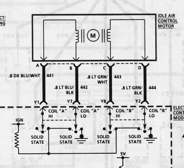
After looking at the schematic for the TPS (below) I could see that it was just a variable potentiometer. GM did not include any specifications for the resistance values if you simply wanted to "ohm it out." Out of curiosity I measured the resistance between pins A & C and discovered that the circuit was completely open unless I placed some sideward pressure on the pins, then I would get a reading. Clearly I had an intermittent connection inside the TPS.

I then measured the resistance between pins B & C and saw that there was a measurable resistance that changed as the TPS actuator arm was moved. This was to be expected.
Without a good path to ground on pin A, the 5 volt reference could not be pulled to ground and so the TPS potentiometer could not return a variable voltage on the wiper contact B.
So, here's the pertinent info:
With a new TPS in hand (Part # 1711-1606) I've documented the values that you should see if you want to do a quick TPS check with an ohm meter:
TPS Actuator Arm at rest: Pins Values (ohms)
A to C = 5.88k
A to B = 2.44k
C to B = 8.32k
Rotating the TPS Actuator Arm: At Rest
 Rotated
A to B = 2.44k 8.26k
C to B = 8.32k 2.39k

Final Notes:
An observant reader might wonder how the ohm value across pins A & B or pins C & B can be greater than the ohm value across pins A & C? Well after opening up my old TPS I've discovered that it isn't quite as simple internally as the schematic diagram would lead you to believe. There's actually two wiper elements inside the TPS and two resistive elements. I'm not going to draw a diagram as it is beyond the scope of this article. Suffice it to say that the TPS works as shown in the schematic but is not constructed as shown in the schematic.
After installing the new TPS, several anomalies disappeared:
1) Random high 1,400 RPM idle
2) Random ECM Code 21's
3) Random loss of 4+3 overdrive
The random loss of the overdrive is a curiosity to me. I can only guess that the bad TPS was making the ECM think I was flooring the accelerator and causing the 4+3 overdrive to kick-out.
Because so much of what the ECM (Electronic Control Module) (computer) does is dependent upon a working Throttle Position Sensor I thought it would be good to provide a little more info to the Corvette hobbyist than what is found in the GM service manuals.
Also, this info applies only to 1985 models, in particular, mine. It may be applicable to later years, but I have no way of determining this.
http://www.chevythunder.com/fuel injection elect. pg B.htm
http://www.chevythunder.com/fuel injection elect. pg B.htm
1st, the IAC motor is not a sensor, it's an actuator.
2nd, yes, engine can run without it if waiting for a new one.
3rd, ensure the idle speed screw is set to achieve an IAC position of around 5-10 counts at hot idle.
4th, ensure the spark plug wires (or any other high voltage wiring) aren't too close to the IAC motor/wiring.
5th, IAC TEST: When turning off the engine, watch the IAC pintle; it should fully close, then open halfway.
ONE WAY
IAC and TPS Adjustment
Tom Keliher
Idle Air Control
Tools needed:
Torx bit # T-20
Paper Clip
Small Punch
Take the paper clip and open it up and form it into a big "U" shape. Insert the clip ends into the ALDL in the 'A' and 'B' pins.
Turn on the ignition, but don't start the engine. Wait 30 seconds. Now, go remove the connector from the IAC.
Start engine. You are now going to adjust "minimum air". There is a Torx screw on the side of the throttle body. This is what needs to be turned to adjust minimum air, or more commonly known as "idle speed". It comes from the factory with a protective metal cap over it. If the cap is still there, use a small punch to knock it out. Set the idle speed to 450-500 rpm, rotating the Torx screw clockwise to raise rpm, and counter-clockwise to lower rpm. Once the idle rpm is set, turn off the engine.
Re-connect the connector onto the IAC. Start engine. Idle speed is now once again governed by the ECM, but your idle should be smooth and steady, approximately 600 rpm in Drive (for unmodified cars).
If you set an SES light by having the IAC disconnected, then after shutting down the engine disconnect the negative battery terminal. Wait 5 minutes. This will clear the ECM of all trouble codes. Re-connect the battery and drive the car for 20 minutes to allow the ECM to relearn your driving style.
Throttle Position Switch (TPS)
Tools needed:
Digital Volt-Ohm-Meter (VOM)
Jumper Wires (make your own)
Auto Xray Scanner (if available) will eliminate the need for VOM and jumper wires.
Turn on ignition, but don't start the engine.
With a scanner: plug in the scanner and read the TPS voltage. It should be 0.54Volts +/- 0.075Volts
With VOM and jumper wires: disconnect the connector from the TPS. Using your jumper wires, make a connection allowing some room for the VOM terminals to contact the jumper leads and read the TPS voltage.
If out of spec, loosen the two screws holding the TPS to the throttle body, and slightly rotate the TPS up or down, reading the voltage until it comes into specification. Tighten screws. Using the throttle lever, rotate the throttle to WOT (wide open throttle). The TPS voltage should be over 4.0 volts. Close the throttle again, and then slowly open it to WOT, observing the voltage reading. It should increase progressively and in a linear fashion. If it sticks or jumps or falls off at all while doing this check, that could mean a bad TPS switch and could be a cause of stumbling and drive ability problems.
After setting the correct voltage, turn off ignition switch. Remove jumpers/scanner and reconnect the TPS connector as required.
be sure you've checked the ignition timing with a decent timing light
SECOND EXPLANATION
Tools needed:
Torx bits or drivers (T-10, T-15, maybe more depending on the application)
Voltmeter (digital is best, but a really accurate analog will work)
Tachometer (the one in the vehicle will work fine if equipped)
Wrenches and an awl (various sizes, only if the idle speed hasn’t ever been set)
Theory of Operation – (lengthy)
A common myth about fuel injected vehicles is that the idle speed is fixed and cannot be adjusted. This isnt quite true; there is a setting. It's called minimum air, which is adjustable on TBI and MPFI vehicles. This setting sets the lowest-possible idle speed for the vehicle. The ECM uses the IAC (idle air controller) to raise the idle speed from this adjustment. So, while the exact idle speed isn’t really adjustable, the minimum idle speed is.
Why adjust the idle speed? Isnt the ECM supposed to do that? Yes it does and it does do a good job, but has to have a starting point. That starting point is called minimum air, or the smallest amount of air allowed to enter the engine with the throttle closed. The ECM can only add air to that minimum setting. If that setting is too high, the ECM cant slow the engine down to an acceptable idle. If the setting is too low, the ECM may not be able to keep the engine running under certain conditions.
Another reason to adjust minimum air is if there has been some repairs to the fuel system. If the throttle body has been removed (i.e. rebuilt or cleaned) or the TPS (throttle position sensor) has been replaced or otherwise disturbed (i.e. loosened the mounting screws unintentionally -- it happens) then minimum air should be adjusted. Any changes that could affect idle speed or idle quality, like performance upgrades or replacing leaking vacuum lines, should be followed by setting minimum air. If youve got an early year TPI , thats designed to use a 9th cold start injector,check the cold start injector as its a potential problem source if its not working correctly.
This adjustment, once learned, only takes a few minutes. It rarely has to be adjusted, but it takes so little time to check (and adjust, if needed) that there’s no reason not to do so.
Checking & Adjustment Instructions
To establish minimum air, the idle speed must be set first. The idle speed screw is sealed with a cap from the factory. This should be removed by removing the throttle body and using an awl to pry the plug off. If this seems scary, have it done. It’s not difficult but it’s not worth risking damage to the throttle body or human flesh to remove the plug. Once the plug has been removed, reinstall the throttle body.
Assuming the idle speed screw is accessible and the throttle body is installed, jumper pins A&B on the ALDL (Assembly Line Data Link) connector under the dash. Pins A&B are on the upper-right-hand side. These are the same two pins to jumper to read codes from the ECM. Now turn the key on (the Check Engine light should be lit) and leave the key on for at least 30 seconds. The computer will extend the IAC plunger all the way out to allow adjustment of the idle speed.
After the 30 second wait, unplug the IAC (square 4-pin connector on the throttle body) WHILE THE KEY IS STILL ON. This prevents the ECM from adjusting the idle speed while you make your adjustments.
Block the drive wheels, set the emergency brake, and start the engine. Set the idle speed by adjusting the idle speed screw. The engine should be at operating temperature for this. The exact setting is on the emissions label on the radiator shroud, but in general, the idle speed should be about 500 RPM in Drive, 700 in Park / Neutral, or if you have a manual transmission, somewhere between 600-800 RPM. Remember that the truck is running during this adjustment, so stay clear of the fan, and make sure it can’t roll or otherwise be put into gear while this is done.
Once the minimum idle speed is set, turn the engine off, reconnect the IAC, and remove the jumper from the ALDL connector. The TPS minimum voltage must now be set. Turning the idle-speed screw may have moved the TPS idle voltage away from the specification, so it should be adjusted next.
Connect a voltmeter between pins A (usually dark blue) and B (usually black, or black/pink) of the TPS, and turn the key on. Dont start the engine. Loosen the two torx screws holding the TPS in place, but don’t remove them. Rotate the TPS until the voltmeter reads between 0.45 and 0.55 volts, with 0.50 being ideal. Tighten the mounting screws (carefully, they thread into soft aluminum) and re-check the voltage to make sure it’s still within range.
Thats it. After the procedure is done once, its easy to remember and do. I hope this helps.
take it a step at a time,set the fuel pressure at 40psi, check for vacuum leaks, and adjust the IAC and TPS and set the timing at 8 degrees per the manual,then drive it for 30 minutes to let the computer learn the conditions it operates in
http://forum.grumpysperformance.com/viewtopic.php?f=32&t=168
http://forum.grumpysperformance.com/viewtopic.php?f=70&t=875
http://forum.grumpysperformance.com/viewtopic.php?f=50&t=821&p=1212&hilit=propane+leaks#p1212
http://forum.grumpysperformance.com/viewtopic.php?f=32&t=1401
http://forum.grumpysperformance.com/viewtopic.php?f=70&t=1809
WATCH THE VIDEO, READ THE LINKS
http://www.youtube.com/watch?v=9CPqbaSg ... re=related
a propane torch is both safer and easier to use as a method to locate vacuum leaks, and most surging IS related to defective injectors or vacuum leaks

(DONT LIGHT IT) just SLIGHTLY open the valve so its allowing gas to flow at a low volume,start the engine and let it idle at the lowest speed you can then place the tip of the UNLIT torch at any suspected vacuum leak and listen for the rpms to increase and watch the tachometer, gas flowing into a vacuum leak will increase engine speed.
look for loose or missing vacuum hoses, cracked or broken power brake connections, emissions system hoses that are loose, vacuum connections to the trans or ignition, loose connectors missing or loose bolts cracked hoses missing assessory connections etc.
naturally this only locates leaks to the outside, and its possible for the intake to suck air from the lifter gallery, so that also needs to be checked if everything else seems to be ok.
read this
viewtopic.php?f=44&t=464
http://www.centuryperformance.com/tunin ... g-148.html
theres a great deal of additional info in the links and sub-links posted in the thread below.when you find you've got questions or just want to fully understand the process reading the links provides you with the required info, so ID strongly suggest taking the time to read thru them, as you'll be amazed at what they contain.
the prime symptoms of a defective IAC is an engine that either won,t idle at a consistent RPM,or it won,t keep running, or it just changes speeds and won,t settle down almost like a vacume leak, a defective or badly adjusted or defective TPS tends to result in a loss of engine response and either fouled plugs or plugs showing excessively lean combustion.
the TPS is easily checked with a multi meter, the IAC can be removed and cleaned, as will the throttle body its installed in, but these do go bad and need replacing
If your trying to isolate and test and get the engine tune correct, on any efi system,
Id suggest you leave the fuel pressure alone if its at least 40 psi and does not exceed about 58 psi,
and if the fuel pressures consistent, and set the spark plug gap at .043-.045 max and keep th engine coolant temps as consistent and near about 180F-190F as you can get them,
the fewer variable your forced to deal with the better, make the changes in INJECTOR PULSE DURATION and ignition advance curves
to vary the fuel/air ratios and cylinder pressure
to avoid detonation and tuning issues
always start by verifying what your dealing with in temps fuel pressure and sensor function, pull trouble codes and read and tuning instructions, get a shop manual and verify sensor functions and electrical connections electrical grounds, ignition firing orders, do a compression test and verify the valve lash, set the valves if that's required, and make sure your not dealing with partially clogged catalytic converter carefully, verify what your dealing with, don,t guess, verify.
I can assure you that most problems are related to guessing or defective sensors, or assuming somethings working, that you fail to verify, like the ohms resistance in ignition wire or the firing order or verifying TDC, vs the damper/timing tabs
having a set of multi meter/timing light, compression gauge, vacuum and fuel pressure gauges and a shop manual is critical.
SKIPPING OR NOT READING LINKED INFO ON THIS WEB SITE IS ALWAYS A BAD IDEA
http://repairs.willcoxcorvette.com/1985-1989-corvette-idle-to-air-mixture-adjustment-procedure/
http://garage.grumpysperformance.co...-cranks-but-won-t-start-intermittently.14212/
1985-1989 Corvette Idle to Air Mixture Adjustment Procedure
By using this procedure you can obtain the proper adjustment between the throttle positioning sensor, distributor timing and the throttle body accelerator cable. Adjusting these components will give you the smoothest possible idle and the correct factory settings for your car.
read these threads and related info
- Use a jumper wire and cross the A and B connectors on the ALDL connector under the dash of the car. You may purchase an AB jumper plug at your local parts store, but a simple jumper wire is all you need!
- Turn on the ignition switch without starting the car. You should hear the cooling fan begin to run and the check engine soon light should start to flash.
- After about 45 seconds with the key on unplug the idle air control solenoid. (IAC)
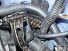
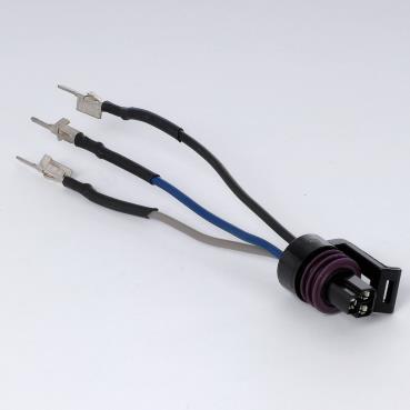
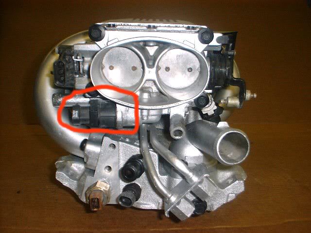
The IAC is located on the passenger side (#70 below) of the throttle body and it has a weather pack type connector. Disconnecting the IAC will stop the IAC motor from moving out of the shutoff bypass air position. Remove the ALDL jumper wire at this point.
- Unplug the tan and black distributor wire located on the driver side of the car beside the wiper motor. This is the wire that sends the distributor to standard timing when the car is in open loop.
- Start the engine and adjust the timing to 6 degrees. When looking at the timing tab you will see a large V in the tab. This V is 0 degrees; count over three marks to the passenger side to obtain 6 degrees of timing. If the marks are not visible, 6 degrees is the first v toward the passenger side. The factory timing and settings for your car is located on a label located on the driver side of the fan shroud and it should be 6 degrees.
- Remove the idle screw plug on the throttle body assembly and adjust the idle to 450 rpm’s. The car may try to stumble and fall while doing this, but get it as close to 450 as possible.
- Re-connect the IAC connector and the distributor wire.
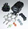
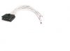
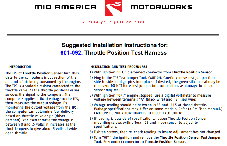
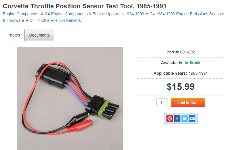
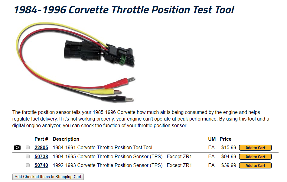
- Set the throttle positioning sensor voltage. (#20 below) To do this loosen the screws and set it to between .54 and .56 volts. Many times this is confused with 5.4 to 5.6 volts. This is not correct and you should make sure the voltage is within the range mentioned first. To know what the setting is on your sensor you will need to purchase a voltage ohms meter and test across the black and dark blue wires located in the connector. You must have the engine key in the on position to test the adjustment voltage and not running. We have a connector available (part number 22805) for testing which will keep you from piercing your wires or you can probe the wires with your ohms meter.
- When you are finished setting the throttle sensor voltage you will need to erase the code 42 from your ECM that will set by having the distributor bypass wire unplugged. You do this either by clearing the code with your diagnostic tester, or remove the battery cable for 30 seconds.
- You may now start the engine and after full warm up hold the idle between 1200 and 1500 rpms for around 2 minutes to clean off the O2 sensor. You should now have a car that will idle properly.
- At this time it is always smart to re-adjust the tension on the accelerator cable at the throttle body injector. Slack in this cable will cause slow throttle response.
http://garage.grumpysperformance.com/index.php?threads/throttle-body-coolant-bye-pass.169/#post-1675
http://garage.grumpysperformance.co...at-manifold-air-temp-sensor.10349/#post-42530
http://garage.grumpysperformance.co...rottle-body-size-52mm-vs-58mm.641/#post-26207
http://garage.grumpysperformance.com/index.php?threads/adjusting-your-tps-and-iac.168/#post-202
removing the coolant passage that provides hot engine coolant to heat the throttle body from the throttle body, is ok, but don,t remove the IAC sensor
keep in mind with some aftermarket efi intakes the throttle body coolant component of the IAC throttle body housing must be removed to allow the t-stat housing to fit
Start and run engine until it reaches operating temperature (closed loop)
Check and set ignition timing to 6 degrees before dead center (BDC) with tan EST wire disconnected
Check and set throttle position sensor (TPS) to .54 (+/- .08) volts at idle
Jumper terminals "A" and "B" on the ALDL
Turn ignition key on and do not start engine
Wait 60 seconds so that the idle air control (IAC) motor fully extends
Without turning ignition key off, remove connector from IAC motor
Turn ignition key off and disconnect ALDL jumper
Attach external RPM meter using Tach port or scanner using ALDL port
Start and run engine until it reaches operating temperature (closed loop)
Remove minimum idle air cap using awl if required
Adjust idle speed to 425 (+/- 25) rpm in either in park or neutral
Turn ignition key off and reconnect EST wire and IAC motor
Check and set throttle position sensor (TPS) to .54 (+/- .08) volts at idle
Reset ECM by disconnecting and reconnecting power at battery terminal
Depress accelerator pedal slightly
Start and run engine for 5 seconds
Turn ignition key off for 10 seconds
Drive vehicle to assist in ECM reprogramming
If you used a scanner, you should see around 20 IAC steps
http://www.ecklerscorvette.com/corvette-idle-air-control-tool-sensor-test-1985-1993.html
I found these bits of linked info that may be useful.
turn on ignition- dont crank, wait 30 sec. unplug IAC, THEN unplug spark advance connector (brown and black I think stripped wire by windshield wiper motor), start car, set idle torx screw on throttle body to idle speed of 450 rpm, yes 450 rpm - may die a time or two but shouldnt, THEN take either an ohm meter or tech1 and loosen TPS sensor - slide up either director to get a reading of .54 to .56 then tighten.
replug IAC and spark advance - car should slowly go to 650 rpm smooth idle. This should verify IAC operation. If ok, disconnect battery to clear code set from unpluggin spark advance earlier. - 5 minute job with TPS harness tester ($20 from ecklers). Good Luck!
when you jumper "A" and "B" on the ALDL and turn ignition on (NO NEED TO CRANK), this will seat or fully extend the IAC pintle. If this does not happen, then I would pull out the factory manual and check the wiring, IAC, and ECM. Don't test the IAC out of the TB, or the pintle will fly out. There are three different pintle tip designs, so they need to match when replacing them. I worked on a 1987 vette that idled like crap, even after a good TB cleaning. What I discovered was that the TB was from a newer vette (1989), and someone carried over the 1987 designed IAC. When we installed a 1989 designed IAC and reset Min Air, it was "Miller time".
YES THERE'S SEVERAL SUB LINKS
(IN MOST OF THE THREADS)
THEY ALL CONTAIN A BIT DIFFERENT RELATED INFO YOU'LL NEED
ANYTIME YOUR DEALING WITH THE ENGINE AND HOW IT RUNS ,
YOULL BE DEALING WITH DIFFERENT ISSUES,
COOLANT AND OIL TEMPS,& PRESSURE
FUEL PRESSURE , INJECTOR FUNCTION
FUEL DELIVERY, PRESSURE & VOLUME
RELATED FUEL / AIR RATIO
EFFECTIVE COMPRESSION & RING SEAL
VALVE TIMING & LIFT & DURATION & VALVE SEAL
IGNITION SPARK TIMING & STRENGTH, & IGNITION ADVANCE CURVE
EXHAUST BACK PRESSURE
SENSOR OUTPUT TO THE CPU
VOLTAGE & GROUNDS
http://www.thirdgen.org/tpimod2
http://www.batee.com/corvette/dcrg/read ... s_sim5.htm
viewtopic.php?f=80&t=728&p=1243&hilit=electrical+connectors#p1243
viewtopic.php?f=32&t=6550&p=20807#p20807
http://www.mamotorworks.com/corvette-c4 ... 6-903.html
http://www.docstoc.com/docs/25331704/Co ... u-1992-Not
viewtopic.php?f=55&t=5307&p=15751&hilit=runners+gaskets+leak#p15751
http://www.iroczone.com/techarttpsadj.html
http://www.haltech.com/product/platinum ... /sport-gm/
http://temp.corvetteforum.net/c4/vader86/tpsiac.html
http://www.golenengineservice.com/html/tps.html
http://www.s-series.org/htm/how2/tpsadjust.htm
viewtopic.php?f=3&t=330&p=5167&hilit=start+sequence#p5167
http://www.jcwhitney.com/autoparts/Sear ... p=ZX503796
http://www.summitracing.com/parts/SUN-CP9001
viewtopic.php?f=44&t=366&p=448#p448
http://www.etoolcart.com/autoxray-scann ... x6000.aspx
viewtopic.php?f=55&t=1475&p=3325#p3325
http://www.corvetteactioncenter.com/kb/ ... Idle+Speed
http://www.thirdgen.org/tpimod1
http://www.ecklerscorvette.com/corvette ... 1991.html#
http://corvette.stealing-fire.com/tps_diagnostics.htm
The TPS (Throttle Position Sensor) on my 1985 Corvette bit the dust after 18 years. I purchased a new one from a local dealership and installed it. In the two years following its replacement, I noticed an erratic idle that got progressively worse. Like most people would do, I refused to believe the TPS was bad because it was "new" even though the cars computer was throwing Code 21's (TPS Signal Voltage High.)
However, when I checked the TPS voltage at idle it was not the .54 volts I expected and nowhere near the .54 volts that I had originally set it to about two years prior, but 2.5 volts.
I searched my GM Corvette service manual and discovered that they only specify an "on-car" diagnostic for the TPS. Needless to say their diagnostic showed the TPS to be bad.
After looking at the schematic for the TPS (below) I could see that it was just a variable potentiometer. GM did not include any specifications for the resistance values if you simply wanted to "ohm it out." Out of curiosity I measured the resistance between pins A & C and discovered that the circuit was completely open unless I placed some sideward pressure on the pins, then I would get a reading. Clearly I had an intermittent connection inside the TPS.
I then measured the resistance between pins B & C and saw that there was a measurable resistance that changed as the TPS actuator arm was moved. This was to be expected.
Without a good path to ground on pin A, the 5 volt reference could not be pulled to ground and so the TPS potentiometer could not return a variable voltage on the wiper contact B.
So, here's the pertinent info:
With a new TPS in hand (Part # 1711-1606) I've documented the values that you should see if you want to do a quick TPS check with an ohm meter:
TPS Actuator Arm at rest: Pins Values (ohms)
A to C = 5.88k
A to B = 2.44k
C to B = 8.32k
Rotating the TPS Actuator Arm: At Rest
A to B = 2.44k 8.26k
C to B = 8.32k 2.39k
Final Notes:
An observant reader might wonder how the ohm value across pins A & B or pins C & B can be greater than the ohm value across pins A & C? Well after opening up my old TPS I've discovered that it isn't quite as simple internally as the schematic diagram would lead you to believe. There's actually two wiper elements inside the TPS and two resistive elements. I'm not going to draw a diagram as it is beyond the scope of this article. Suffice it to say that the TPS works as shown in the schematic but is not constructed as shown in the schematic.
After installing the new TPS, several anomalies disappeared:
1) Random high 1,400 RPM idle
2) Random ECM Code 21's
3) Random loss of 4+3 overdrive
The random loss of the overdrive is a curiosity to me. I can only guess that the bad TPS was making the ECM think I was flooring the accelerator and causing the 4+3 overdrive to kick-out.
Because so much of what the ECM (Electronic Control Module) (computer) does is dependent upon a working Throttle Position Sensor I thought it would be good to provide a little more info to the Corvette hobbyist than what is found in the GM service manuals.
Also, this info applies only to 1985 models, in particular, mine. It may be applicable to later years, but I have no way of determining this.
http://www.chevythunder.com/fuel injection elect. pg B.htm
http://www.chevythunder.com/fuel injection elect. pg B.htm
1st, the IAC motor is not a sensor, it's an actuator.
2nd, yes, engine can run without it if waiting for a new one.
3rd, ensure the idle speed screw is set to achieve an IAC position of around 5-10 counts at hot idle.
4th, ensure the spark plug wires (or any other high voltage wiring) aren't too close to the IAC motor/wiring.
5th, IAC TEST: When turning off the engine, watch the IAC pintle; it should fully close, then open halfway.
ONE WAY
IAC and TPS Adjustment
Tom Keliher
Idle Air Control
Tools needed:
Torx bit # T-20
Paper Clip
Small Punch
Take the paper clip and open it up and form it into a big "U" shape. Insert the clip ends into the ALDL in the 'A' and 'B' pins.
Turn on the ignition, but don't start the engine. Wait 30 seconds. Now, go remove the connector from the IAC.
Start engine. You are now going to adjust "minimum air". There is a Torx screw on the side of the throttle body. This is what needs to be turned to adjust minimum air, or more commonly known as "idle speed". It comes from the factory with a protective metal cap over it. If the cap is still there, use a small punch to knock it out. Set the idle speed to 450-500 rpm, rotating the Torx screw clockwise to raise rpm, and counter-clockwise to lower rpm. Once the idle rpm is set, turn off the engine.
Re-connect the connector onto the IAC. Start engine. Idle speed is now once again governed by the ECM, but your idle should be smooth and steady, approximately 600 rpm in Drive (for unmodified cars).
If you set an SES light by having the IAC disconnected, then after shutting down the engine disconnect the negative battery terminal. Wait 5 minutes. This will clear the ECM of all trouble codes. Re-connect the battery and drive the car for 20 minutes to allow the ECM to relearn your driving style.
Throttle Position Switch (TPS)
Tools needed:
Digital Volt-Ohm-Meter (VOM)
Jumper Wires (make your own)
Auto Xray Scanner (if available) will eliminate the need for VOM and jumper wires.
Turn on ignition, but don't start the engine.
With a scanner: plug in the scanner and read the TPS voltage. It should be 0.54Volts +/- 0.075Volts
With VOM and jumper wires: disconnect the connector from the TPS. Using your jumper wires, make a connection allowing some room for the VOM terminals to contact the jumper leads and read the TPS voltage.
If out of spec, loosen the two screws holding the TPS to the throttle body, and slightly rotate the TPS up or down, reading the voltage until it comes into specification. Tighten screws. Using the throttle lever, rotate the throttle to WOT (wide open throttle). The TPS voltage should be over 4.0 volts. Close the throttle again, and then slowly open it to WOT, observing the voltage reading. It should increase progressively and in a linear fashion. If it sticks or jumps or falls off at all while doing this check, that could mean a bad TPS switch and could be a cause of stumbling and drive ability problems.
After setting the correct voltage, turn off ignition switch. Remove jumpers/scanner and reconnect the TPS connector as required.
be sure you've checked the ignition timing with a decent timing light
SECOND EXPLANATION
Tools needed:
Torx bits or drivers (T-10, T-15, maybe more depending on the application)
Voltmeter (digital is best, but a really accurate analog will work)
Tachometer (the one in the vehicle will work fine if equipped)
Wrenches and an awl (various sizes, only if the idle speed hasn’t ever been set)
Theory of Operation – (lengthy)
A common myth about fuel injected vehicles is that the idle speed is fixed and cannot be adjusted. This isnt quite true; there is a setting. It's called minimum air, which is adjustable on TBI and MPFI vehicles. This setting sets the lowest-possible idle speed for the vehicle. The ECM uses the IAC (idle air controller) to raise the idle speed from this adjustment. So, while the exact idle speed isn’t really adjustable, the minimum idle speed is.
Why adjust the idle speed? Isnt the ECM supposed to do that? Yes it does and it does do a good job, but has to have a starting point. That starting point is called minimum air, or the smallest amount of air allowed to enter the engine with the throttle closed. The ECM can only add air to that minimum setting. If that setting is too high, the ECM cant slow the engine down to an acceptable idle. If the setting is too low, the ECM may not be able to keep the engine running under certain conditions.
Another reason to adjust minimum air is if there has been some repairs to the fuel system. If the throttle body has been removed (i.e. rebuilt or cleaned) or the TPS (throttle position sensor) has been replaced or otherwise disturbed (i.e. loosened the mounting screws unintentionally -- it happens) then minimum air should be adjusted. Any changes that could affect idle speed or idle quality, like performance upgrades or replacing leaking vacuum lines, should be followed by setting minimum air. If youve got an early year TPI , thats designed to use a 9th cold start injector,check the cold start injector as its a potential problem source if its not working correctly.
This adjustment, once learned, only takes a few minutes. It rarely has to be adjusted, but it takes so little time to check (and adjust, if needed) that there’s no reason not to do so.
Checking & Adjustment Instructions
To establish minimum air, the idle speed must be set first. The idle speed screw is sealed with a cap from the factory. This should be removed by removing the throttle body and using an awl to pry the plug off. If this seems scary, have it done. It’s not difficult but it’s not worth risking damage to the throttle body or human flesh to remove the plug. Once the plug has been removed, reinstall the throttle body.
Assuming the idle speed screw is accessible and the throttle body is installed, jumper pins A&B on the ALDL (Assembly Line Data Link) connector under the dash. Pins A&B are on the upper-right-hand side. These are the same two pins to jumper to read codes from the ECM. Now turn the key on (the Check Engine light should be lit) and leave the key on for at least 30 seconds. The computer will extend the IAC plunger all the way out to allow adjustment of the idle speed.
After the 30 second wait, unplug the IAC (square 4-pin connector on the throttle body) WHILE THE KEY IS STILL ON. This prevents the ECM from adjusting the idle speed while you make your adjustments.
Block the drive wheels, set the emergency brake, and start the engine. Set the idle speed by adjusting the idle speed screw. The engine should be at operating temperature for this. The exact setting is on the emissions label on the radiator shroud, but in general, the idle speed should be about 500 RPM in Drive, 700 in Park / Neutral, or if you have a manual transmission, somewhere between 600-800 RPM. Remember that the truck is running during this adjustment, so stay clear of the fan, and make sure it can’t roll or otherwise be put into gear while this is done.
Once the minimum idle speed is set, turn the engine off, reconnect the IAC, and remove the jumper from the ALDL connector. The TPS minimum voltage must now be set. Turning the idle-speed screw may have moved the TPS idle voltage away from the specification, so it should be adjusted next.
Connect a voltmeter between pins A (usually dark blue) and B (usually black, or black/pink) of the TPS, and turn the key on. Dont start the engine. Loosen the two torx screws holding the TPS in place, but don’t remove them. Rotate the TPS until the voltmeter reads between 0.45 and 0.55 volts, with 0.50 being ideal. Tighten the mounting screws (carefully, they thread into soft aluminum) and re-check the voltage to make sure it’s still within range.
Thats it. After the procedure is done once, its easy to remember and do. I hope this helps.
take it a step at a time,set the fuel pressure at 40psi, check for vacuum leaks, and adjust the IAC and TPS and set the timing at 8 degrees per the manual,then drive it for 30 minutes to let the computer learn the conditions it operates in
http://forum.grumpysperformance.com/viewtopic.php?f=32&t=168
http://forum.grumpysperformance.com/viewtopic.php?f=70&t=875
http://forum.grumpysperformance.com/viewtopic.php?f=50&t=821&p=1212&hilit=propane+leaks#p1212
http://forum.grumpysperformance.com/viewtopic.php?f=32&t=1401
http://forum.grumpysperformance.com/viewtopic.php?f=70&t=1809
WATCH THE VIDEO, READ THE LINKS
http://www.youtube.com/watch?v=9CPqbaSg ... re=related
a propane torch is both safer and easier to use as a method to locate vacuum leaks, and most surging IS related to defective injectors or vacuum leaks
(DONT LIGHT IT) just SLIGHTLY open the valve so its allowing gas to flow at a low volume,start the engine and let it idle at the lowest speed you can then place the tip of the UNLIT torch at any suspected vacuum leak and listen for the rpms to increase and watch the tachometer, gas flowing into a vacuum leak will increase engine speed.
look for loose or missing vacuum hoses, cracked or broken power brake connections, emissions system hoses that are loose, vacuum connections to the trans or ignition, loose connectors missing or loose bolts cracked hoses missing assessory connections etc.
naturally this only locates leaks to the outside, and its possible for the intake to suck air from the lifter gallery, so that also needs to be checked if everything else seems to be ok.
read this
viewtopic.php?f=44&t=464
http://www.centuryperformance.com/tunin ... g-148.html
Last edited by a moderator: