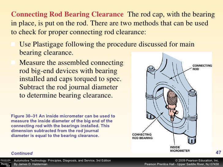
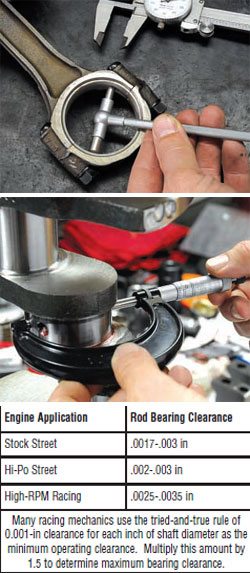
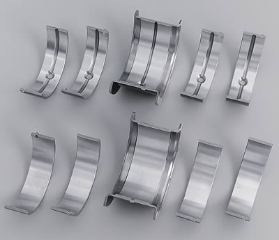
Rod bearings 0.002 - 0.025" , side clearance 0.010 - 0.020"
Main bearings 0.002 - 0.003" for most engines ( 0.020-0.025 bearing clearance on small blocks, .025-.027 bearing clearance is about ideal, on big blocks ), 0.005 - 0.007 crankshaft end play
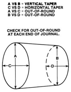
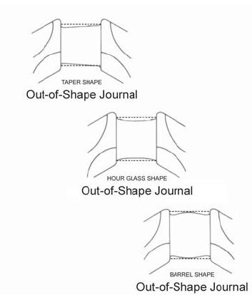
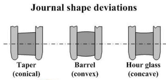
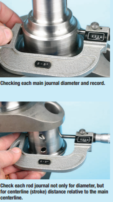
this is rather good advise, but consider the bearing clearance must be checked carefully and verified, and the crank journals must be carefully checked for taper, roundness finish and journals must be concentric
Piston to head clearance 0.038 MINIMUM including gasket (.038-.042 quench is what you want with steel rods)(steel rods), 0.060" MINIMUM quench aluminum rods
Valve to piston clearance MINIMUM 0.100" exhaust , 0.080" intake NO VALVE FLOAT
Recommended: 0.080 intake, 0.100 Exhaust (steel rods) 0.100 intake, 0.120 Exhaust aluminum rods
TORQUE SPECS CAN BE FOUND HERE IN THIS LINK
http://garage.grumpysperformance.com/index.php?threads/torque-specs-calculator-links-etc.1222/
http://garage.grumpysperformance.com/index.php?threads/rotating-assembly-bearings.9527/
together correctly
http://www.harborfreight.com/36-piece-3 ... 60669.html
watch this video


Chevy V8 bore & stroke chart
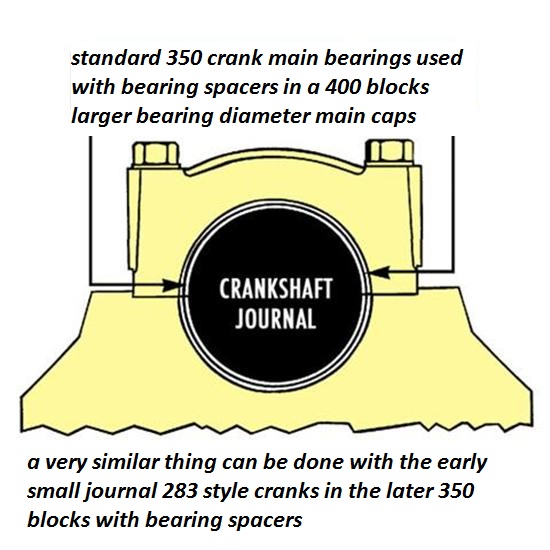
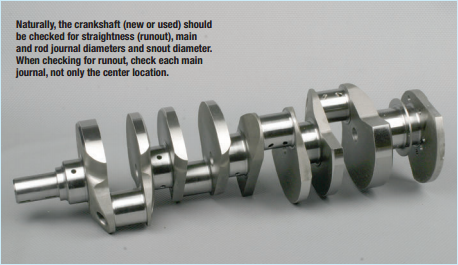
always accurately measure the crank main journals, and remember the crank and block bearing sizes on a 400 sbc and 350 smc are different as are the early 283-327 sbc
Chevy V8 Crankshaft Journal Sizes
Here's a list of Chevy V-8 crankshaft journal sizes. All journal sizes are given in "STANDARD" sizes. Your crankshaft may have been cut down in size previously by a machine shop. Make sure your crank will work in the block you have. Blocks were made for each crank main journal size. If you are putting a "small" or "medium" journal smallblock crank into a "medium" or "large" journal smallblock block you will need crank bearing "spacers" or use special "thick" bearings available from aftermarket suppliers.
Chevy Smallblock V8 Crankshaft Journal Sizes
Gen.I, "Small Journal"
265...Mains-2.30"-Rods-2.00"
283...Mains-2.30"-Rods-2.00"
302...Mains-2.30"-Rods-2.00"
327...Mains-2.30"-Rods-2.00"
Gen.I, "Medium Journal", includes "Vortec" 305 and 350 thru '98
262...Mains-2.45"-Rods-2.10"
267...Mains-2.45"-Rods-2.10"
302...Mains-2.45"-Rods-2.10"
305...Mains-2.45"-Rods-2.10"
307...Mains-2.45"-Rods-2.10"
327...Mains-2.45"-Rods-2.10"
350...Mains-2.45"-Rods-2.10"
Gen.I, "Large Journal"
400...Mains-2.65"-rods-2.10"
Non-production Gen.I combination, using Gen.I 400 crank in Gen.I 350 block
383...400 crank, Mains cut to 2.45"-Rods-2.10"
Non-production Gen.I combination, using Gen.I 350 crank in Gen.I 400 block
377..."Spacer" or "thick" main bearings with 350 crank-Rods-2.10"
Gen.II, "Medium Journal", includes "L-99" 265, "LT-1" 350, "LT-4" 350
265...Mains-2.45"-rods-2.10"
305...Mains-2.45"-Rods-2.10"
350...Mains-2.45"-Rods-2.10"
Non-production Gen.II combination, using Gen.II 265 "L-99" crank in Gen.II 350 block
302...Mains-2.45"-Rods-2.10"
Gen.III, includes '97-2005 "LS-1" Corvette, Firebird, Camaro
345...Mains-2.558"-Rods-2.10"
Corvette "ZR-1", DOHC, "LT-5"
350...Mains-2.76"-Rods-2.10"


CID BORE STROKE
262 = 3.671" x 3.10" (Gen. I, 5.7" rod)
265 = 3.750" x 3.00" ('55-'57 Gen.I, 5.7" rod)
265 = 3.750" x 3.00" ('94-'96 Gen.II, 4.3 liter V-8 "L99", 5.94" rod)
267 = 3.500" x 3.48" (Gen.I, 5.7" rod)
283 = 3.875" x 3.00" (Gen.I, 5.7" rod)
293 = 3.779" x 3.27" ('99-later, Gen.III, "LR4" 4.8 Liter Vortec, 6.278" rod)
302 = 4.000" x 3.00" (Gen.I, 5.7" rod)
305 = 3.736" x 3.48" (Gen.I, 5.7" rod)
307 = 3.875" x 3.25" (Gen.I, 5.7" rod)
325 = 3.779" x 3.622" ('99-later, Gen.III, "LM7", "LS4 front wheel drive V-8" 5.3 Liter Vortec, 6.098" rod)
327 = 4.000" x 3.25" (Gen.I, 5.7" rod)
345 = 3.893" x 3.622" ('97-later, Gen.III, "LS1", 6.098" rod)
350 = 4.000" x 3.48" (Gen.I, 5.7" rod)
350 = 4.000" x 3.48" ('96-'01, Gen. I, Vortec, 5.7" rod)
350 = 3.900" x 3.66" ('89-'95, "LT5", in "ZR1" Corvette 32-valve DOHC, 5.74" rod)
364 = 4.000" x 3.622" ('99-later, Gen.III, "LS2", "LQ4" 6.0 Liter Vortec, 6.098" rod)
376 = 4.065" x 3.622" (2007-later, Gen. IV, "L92", Cadillac Escalade, GMC Yukon)
383 = 4.000" x 3.80" ('00, "HT 383", Gen.I truck crate motor, 5.7" rod)
400 = 4.125" x 3.75" (Gen.I, 5.565" rod)
427 = 4.125" x 4.00" (2006 Gen.IV, LS7 SBC, titanium rods)
Two common, non-factory smallblock combinations:
377 = 4.155" x 3.48" (5.7" or 6.00" rod)
400 block and a 350 crank with "spacer" main bearings
383 = 4.030" x 3.75" (5.565" or 5.7" or 6.0" rod)
350 block and a 400 crank, main bearing crank journals
cut to 350 size
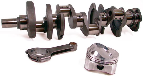
ALL production big blocks used a 6.135" length rod.
CHEVY BIG BLOCK V-8 BORE AND STROKE
366T = 3.935" x 3.76"
396 = 4.096" x 3.76"
402 = 4.125" x 3.76"
427 = 4.250" x 3.76"
427T = 4.250" x 3.76"
454 = 4.250" x 4.00"
477= 4.5" bore x 3.76" stroke
496 = 4.250" x 4.37" (2001 Vortec 8100, 8.1 liter)
502 = 4.466" x 4.00"
557T= 4.5 bore 4.375" stroke
572T = 4.560" x 4.375" (2003 "ZZ572" crate motors)
T = Tall Deck
ALL production big blocks used a 6.135" length rod.
MEASURE CAREFULLY
http://garage.grumpysperformance.co...ting-resistance-to-look-for.11312/#post-51472
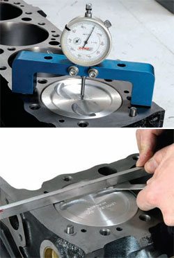

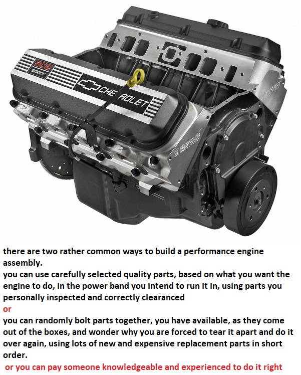
the most important and effective performance asset you have is simply your ability to ask yourself questions, the ability to think logically isolate and test components carefully and doing the research if its required to find the best answer's you'll need.
its the attention to details and checking clearance etc. and time and care taken,
that makes the difference between a barely or average functional ,
and a rather exceptional engine build, yes the urge to get it running is strong,
but getting it done correctly is the goal
http://garage.grumpysperformance.co...ting-resistance-to-look-for.11312/#post-51472
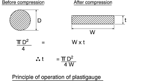
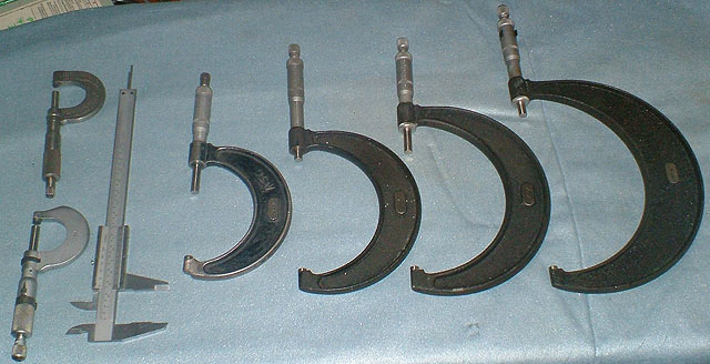
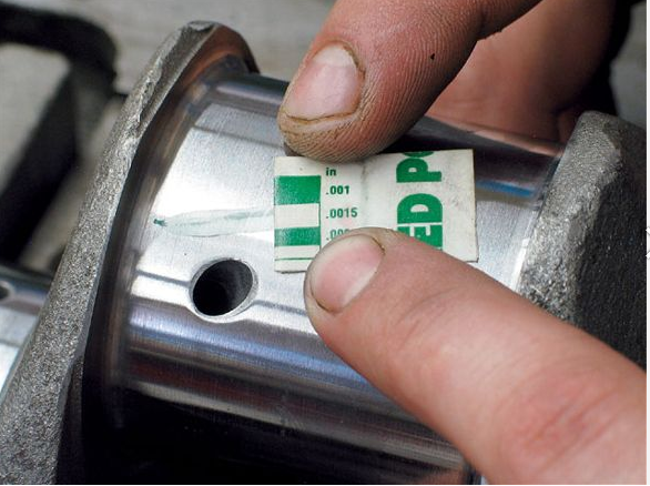
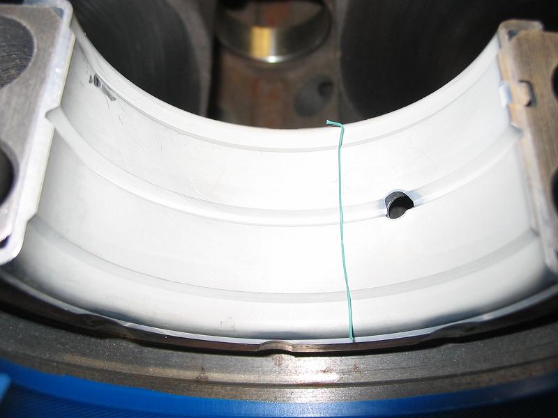
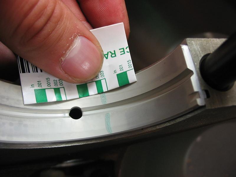
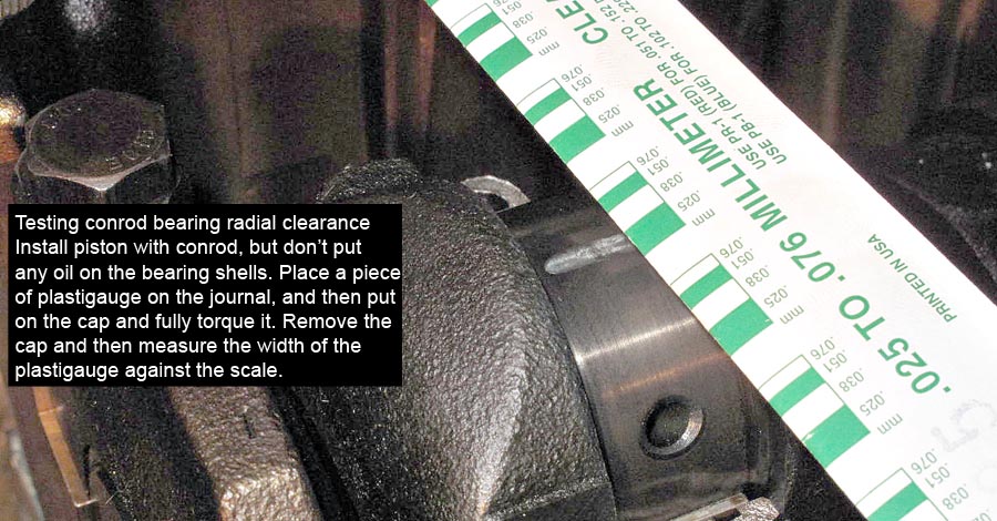
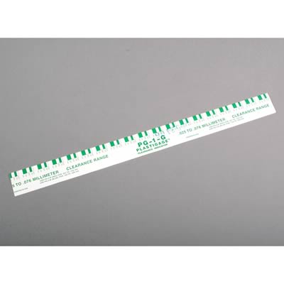
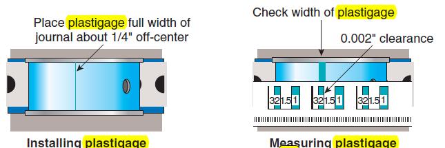
yes I use both micrometers and snap gauges and cross check with plasti-gauge
and yes when you compare the crushed width of the plasti-gauge youll find it rarely falls as an exact match to the bar chart tape that is packaged with it so you can judge clearance based on crush width
http://garage.grumpysperformance.com/index.php?threads/bearing-clearances.2726/
failure to take the time and effort to read the sub linked info,
WILL usually result in
significantly increased cost and delays in engine assembly!
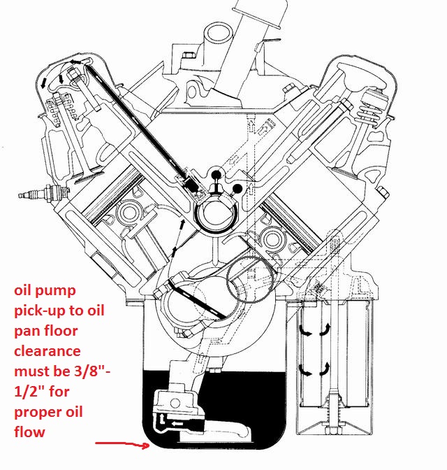
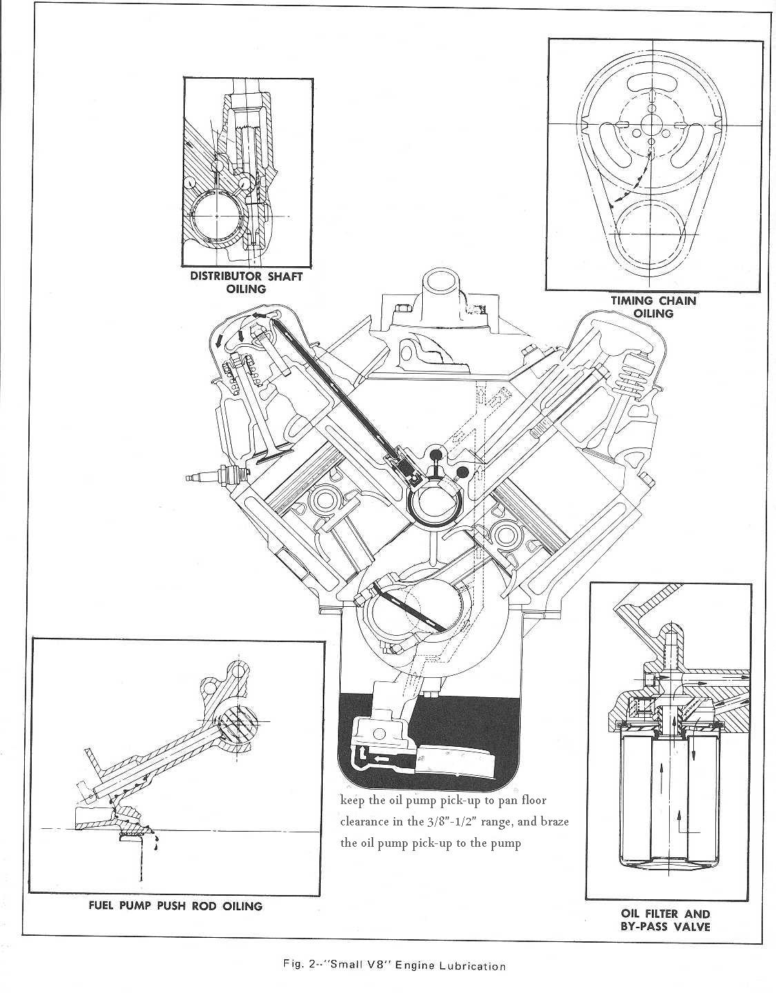
yes Ive seen several cases where guys failed to install the oil pump pick-up at the proper minimum 3/8"-to-1/2" off the oil pan floor clearance,
the result is the pump is starved for oil intake flow.
http://garage.grumpysperformance.co...m-sure-your-convinced-its-the-oil-pump.11085/
http://garage.grumpysperformance.co...m-oil-pump-installed-now-no-oil-pressure.525/
http://garage.grumpysperformance.com/index.php?threads/bbc-oil-pump-in-a-sbc.2598/
viewtopic.php?f=53&t=852&p=1311&hilit=checking+bearings#p1311
https://www.fordmuscle.com/fundamentals/plastiguage/
http://www.autozone.com/test-scan-and-s ... 36168_0_0/
http://www.hotrod.com/how-to/additional ... icrometer/
viewtopic.php?f=53&t=9214&p=43456&hilit=plastigauge#p43456
http://video.answers.com/engine-bearing ... s-39414874
http://www.summitracing.com/parts/MEL-10990/?rtype=4
http://www.engineparts.com/techbulletin ... 1-205R.pdf
http://www.stealth316.com/misc/clevite- ... ooving.pdf
http://www.circletrack.com/enginetech/c ... ce_basics/
http://garage.grumpysperformance.co...l-pressure-switch-on-fuel-pump-circuit.16013/
http://www.vsihp.com/library/CleviteEng ... sGuide.pdf
http://www.bracketracer.com/engine/mains/mains.htm
http://cleviteonengine.com/askclevite.asp
http://www.jegs.com/p/Clevite/Clevite-7 ... 4/10002/-1


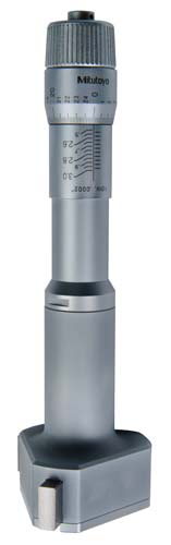
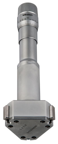
http://ecatalog.mitutoyo.com/Holtest-Ty ... C1530.aspx
Rod bearings 0.002 - 0.025" , side clearance 0.010 - 0.020"
Main bearings 0.002 - 0.003" for most engines ( 0.020-0.025 bearing clearance on small blocks, .025-.027 bearing clearance is about ideal, on big blocks ), 0.005 - 0.007 crankshaft end play
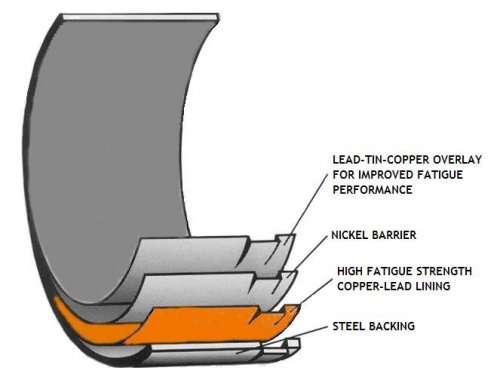
Stock Bearing Clearances
The general rule of thumb for bearing clearances is 0.0010 inch for every 1 inch of journal diameter. That's true for mains and rods, and applies to almost all engines. For the small-block's 2-inch rod journals, that means 0.002 inch of clearance between the rod journal and bearing, by the rule of thumb. The GM-specified tolerances are 0.002 to 0.0025 inch, which lines up well with the rule. Side clearances come in at 0.010 to 0.020 inch, as specified by GM. The clearance rule applies to most engines, but it's generally best to avoid going below 0.0020 inch on any bearing, regardless of the journal diameter.
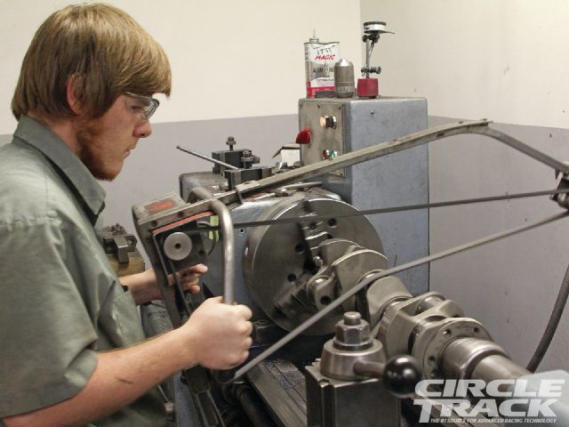
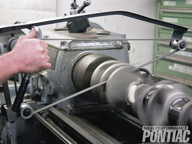
YOU ALSO HAVE THE OPTION OF HAVING THE CRANK JOURNALS MICRO POLISHED WHILE REMOVING JUST ENOUGH SURFACE FROM THOSE JOURNALS TO GAIN THE REQUIRED CLEARANCE, IF THE CLEARANCE IS TOO TIGHT
http://garage.grumpysperformance.com/index.php?threads/precision-measuring-tools.1390/#post-68861
WATCH VIDEO most larger machine shops can do that cheaply and gain you the required clearance
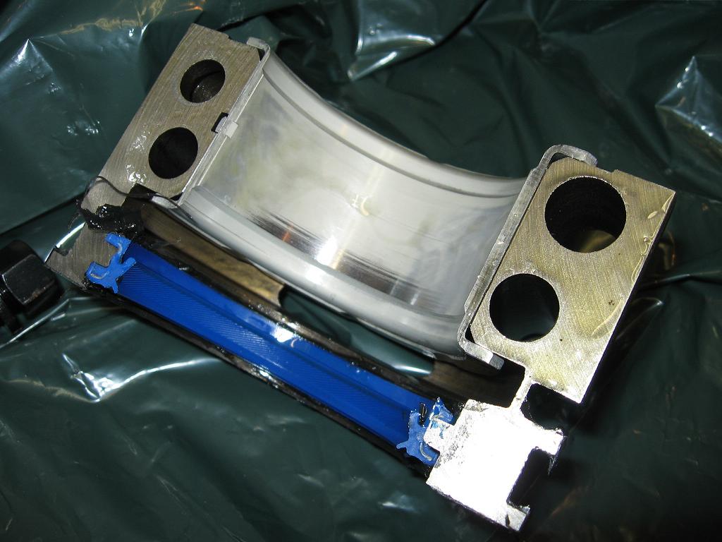
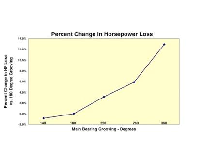
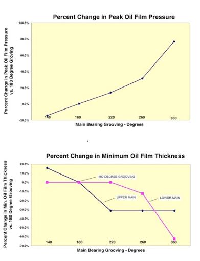
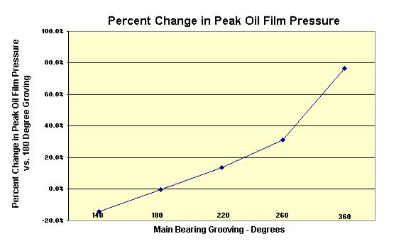
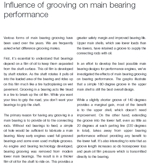
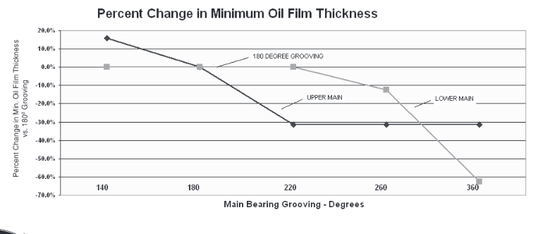
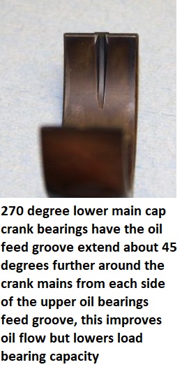
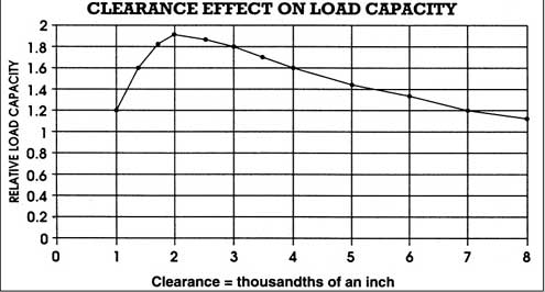
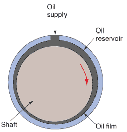
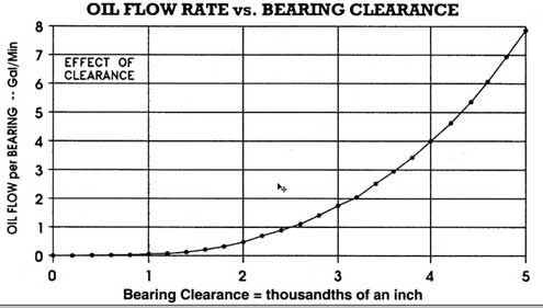
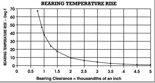
Influence of Grooved Main Bearings on Performance
Manufacturers are frequently asked what difference grooving makes. Various forms of main bearing grooving have been used over the years.
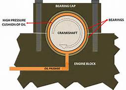
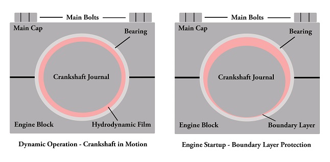
It’s essential to understand that bearings depend on a film of oil to keep them separated from the shaft surface. This oil film is developed by shaft rotation. As the shaft rotates it pulls oil into the loaded area of the bearing and rides up on this film much like a tire hydroplaning on wet pavement.
Grooving in a bearing acts like tread in a tire to break up the oil film. While you want your tires to grip the road, you don’t want your bearings to grip the shaft, so grooving is bad for maintaining an oil film. The primary reason for having any grooving in a main bearing is to provide oil to the connecting rods. Without rod bearings to feed, a simple oil hole would be sufficient to lubricate a main bearing.
Many early engines used full grooved bearings and some even used multiple grooves. Those choices were based on what engineers knew at the time. As engine and bearing technology developed, the negative effect of grooving was recognized and bearing grooving was removed from modern lower main bearings. The result is in a thicker film of oil for the shaft to ride on.
This provides a greater safety margin and improved bearing life. Upper main shells, which see lower loads than the lowers, and hence don’t apply the same load to the oil film, have retained a groove to supply the connecting rods with oil.
In an effort to develop the best possible main bearing designs for high performance engines, manufacturers have investigated the effects of main bearing grooving on bearing performance. The graphs (Figure 1) illustrate that a simple 180° groove in the upper main shell is still the best overall design.
While a slightly shorter groove of 140° provides a marginal gain, most of the benefit is to the upper shell, which doesn’t need improvement. On the other hand, extending the groove into the lower half, even as little as 20° at each parting line (220° in total), takes away from upper bearing performance without providing any benefit to the lower half. It’s also interesting to note that as groove length increases so does horsepower loss and peak oil film pressure, which is transmitted directly to the bearing.
Notes: You will still find some full-grooved main sets offered for older engines where demand is low and the engineering cost to bring the sets to current standards is not warranted (bearings generally represent the technology of the time the engine was developed).
http://www.stockcarracing.com/techartic ... ewall.html
http://www.goodson.com/store/template/p ... f3f1075a76
http://www.chevyhiperformance.com/tech/ ... index.html
http://www.circletrack.com/tipstricks/4 ... index.html
http://www.carcraft.com/techarticles/cc ... _tips.html
http://www.hotrod.com/techarticles/engi ... index.html
http://www.engineparts.com/techbulletin ... 1-205R.pdf
http://www.engineersedge.com/lubrication/molybdenum_disulfide_characteristics.htm
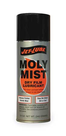
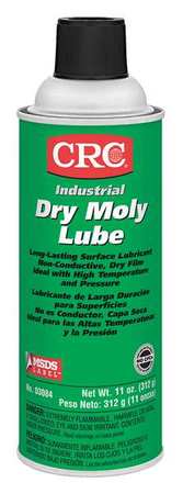
when assembling any engines valve train component parts and bearing surfaces,should be carefully cleaned and soaked with moly spray and then coated with moly assembly lube prior to assembly, Moly exists as microscopic hexagonal crystal platelets Several molecules make up one of these platelets. A single molecule of Moly contains two sulfur atoms and one molybdenum atom. Moly platelets are attracted to metal surfaces. This attraction and the force of moving engine parts rubbing across one another provide the necessary thermochemical reaction necessary for Moly to form an overlapping protective coating like armor on all of your engine parts. This protective armor coating has a number of properties that are very beneficial for your engine.

The Moly platelets that make up the protective layers on your engine surfaces slide across one another very easily. Instead of metal rubbing against metal, you have Moly platelets moving across one another protecting and lubricating the metal engine parts.
This coating effectively fills in the microscopic pores that cover the surface of all engine parts, making them smoother. This feature is important in providing an effective seal on the combustion chamber. By filling in the craters and pores Moly improves this seal allowing for more efficient combustion and engine performance.

This overlapping coating of Moly also gives protection against loading (perpendicular) forces. These forces occur on the bearings, and lifters. The high pressures that occur between these moving parts tend to squeeze normal lubricants out.

http://www.carbideselect.com/burshpescuts.php
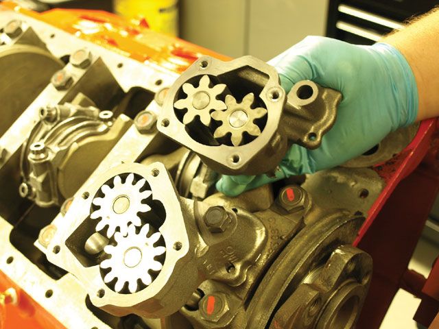
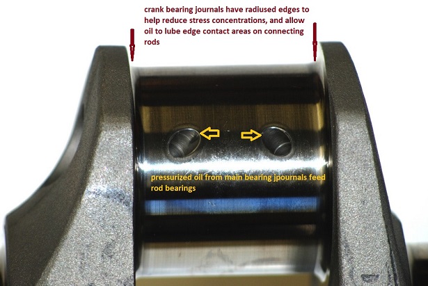
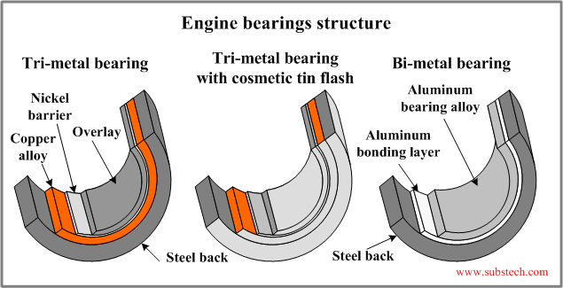
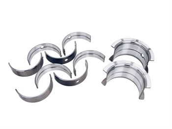
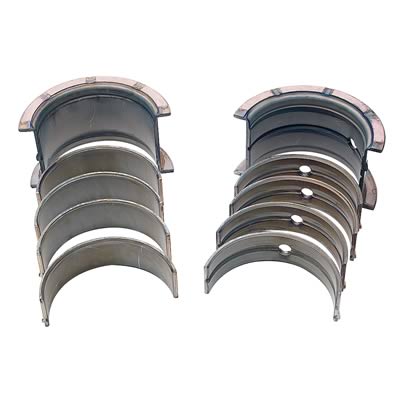
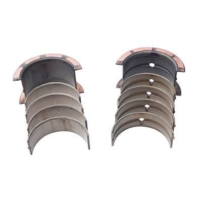
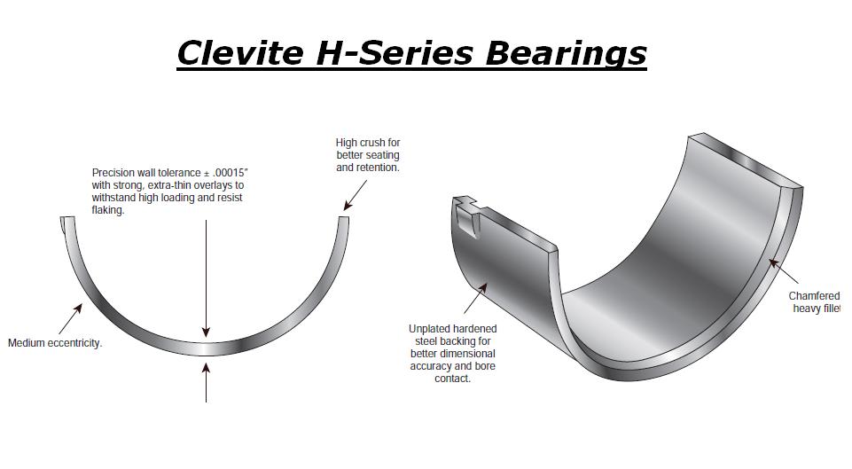
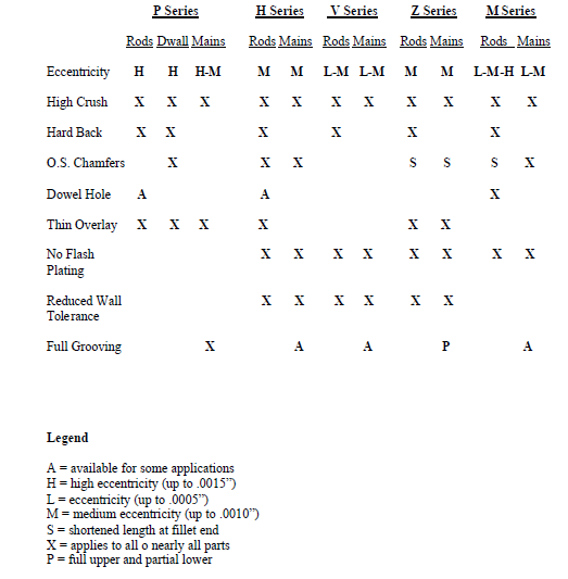
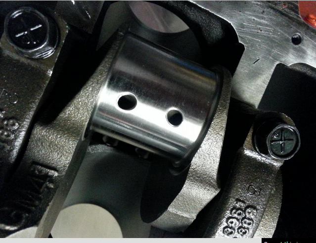
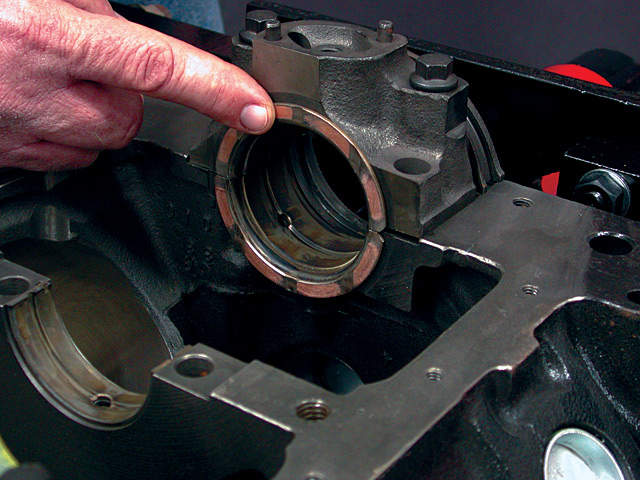
Ive generally found the H-series bearings are the best choice, remember most after market cranks have beveled crank journals requiring matched beveled edge (H) style bearing inserts, standard bearings will have the edge of the bearing insert bind on the radias edge

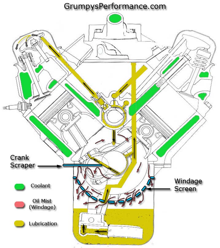
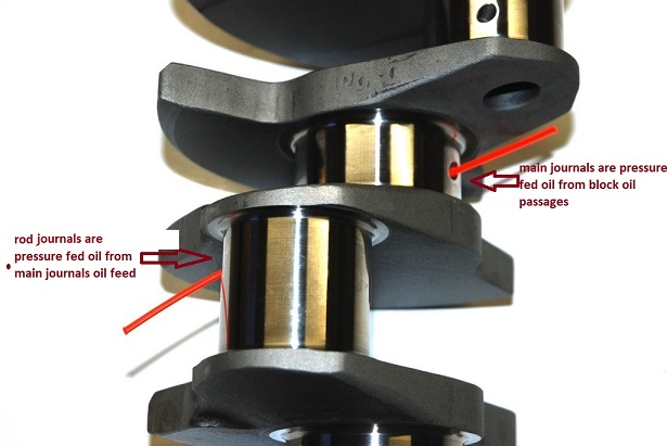
in a properly set up block a pressurized oil film supports the cam and main bearings
http://carcraft.automotive.com/66890/cc ... -tips.html
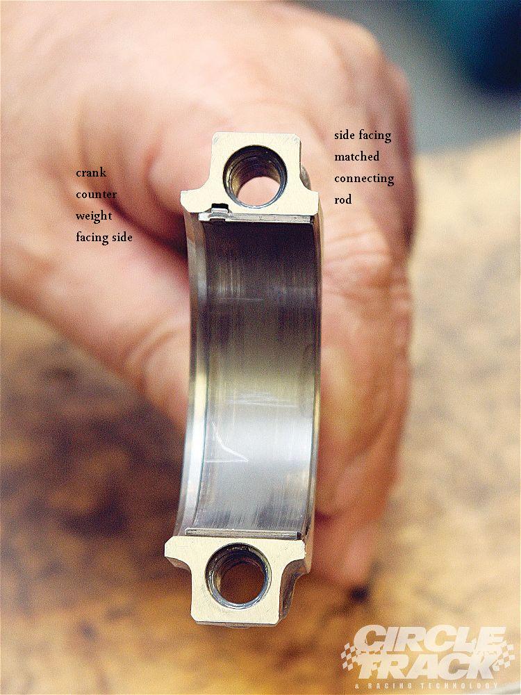
bearings AND connecting rods have an inner facing side and outer side the inner side facing the matching rod has far less edge clearance because they don,t need the radias that is required for the edge of the crank journals
IVE dunked my piston/ring assembly's in a can of MARVEL MYSTERY OIL just before installation with a ring compressor and have never seen the slightest indication of problems either on ring sealing getting the rings broken in, or on tearing the engines down later for inspections the amounts not that great, ideally each one installed adds a bit of resistance but at no time should the short block take over 40 ft lbs ABSOLUTE MAXIMUM to start it spinning,and LESS than 20 lbs to keep it moving, even with all the rings and pistons installed,yes you need to verify the bearing clearances during assembly and IT SHOULD take between 20lbs-25 lbs to start it spinning if the clearances are correct! and LESS than 20 lbs to keep it moving
IF it takes over 40 ft lbs to get it rotating ,youll need too DISASSEMBLE and FIND OUT WHY!
http://www.engineprofessional.com/TB/EPQ410_10-18.pdf

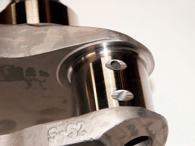
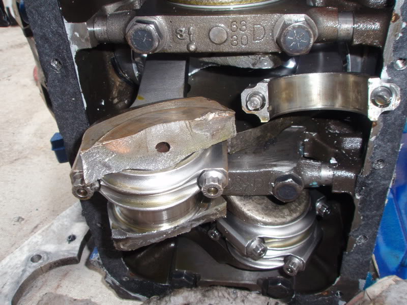
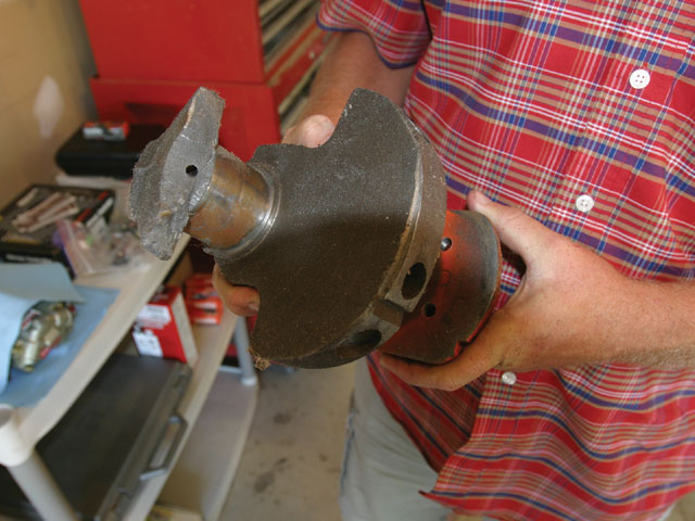
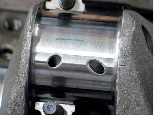
when you get the crank polished take the time and effort to clean out any cross drill oil feed passages and to very carefully de-burr the passage opening edges, as this is a very commonly overlooked issue, below is what at first looks like a perfectly polished crank, with oil feed passages to the rod bearings, but the deep scratches the oil feed passage openings left in the rod bearing surfaces bare witness, after a single rotation, during a trial assembly show they are HARDLY burr free or ready for use, and obviously he failed to check each rod bearing during the assembly process, and probably ignored , what was very likely un-even or rather excessive resistance to the crank rotation. which should never exceed about 40 ft lbs even with all 8 rod bearings and pistons installed
having the correct bearing clearances are critical, to durability, generally you'll want no less than .0022-.0025 with .0025-.0028 preferred for most performance use. I prefer .0025-.0028 most of the time
Both rods & mains.
Bearing Tips And Tricks
1. Always check your micrometer with a standard before measuring.
2. Always use the same micrometer for the journals and to set the inside mic diameter.
3. Torque the rods and mains to spec before measuring a bearing inside diameter.
4. Changing rod bolts or moving from bolts to studs in the main caps will affect bearing clearance.
5. Temperature will affect the accuracy of the micrometer and the size of journal diameters both inside and out.
6. If you have one tight and one loose rod-bearing combination, try switching the bearings between the two. We've seen this work several times when the clearances are just a little bit off.
7. Never mix different bearing families when customizing bearing clearance. If you are using Federal-Mogul coated bearings, don't mix in a half shell uncoated race bearing.
http://www.robertpowersmotorsports.com/Tech2.html
http://www.stockcarracing.com/techartic ... index.html
http://mechdb.com/index.php/Plastigagin ... clearances
from chevy high performance mag
MORE USEFUL INFO
BE 100% SURE that the oil pump bolt or STUD doesn,t protrude past the inner main cap surface , because if it bears on the rear main bearing shell it will almost always result in a quickly failed rear bearing
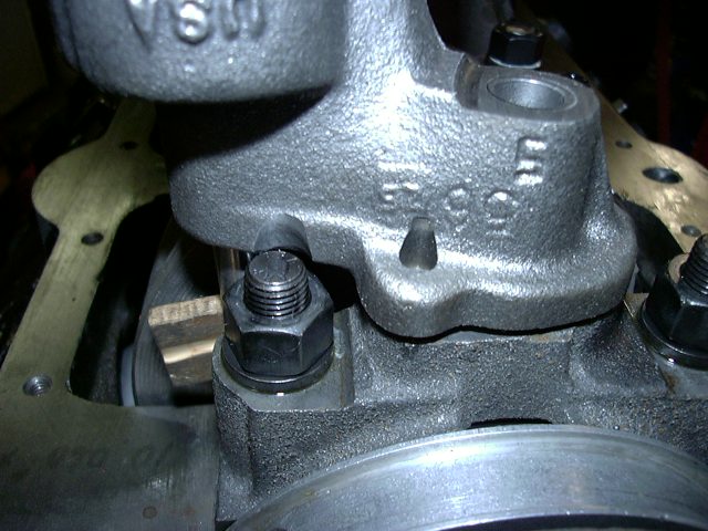
failure to use the correct stud, bolt or nut or check clearances when mounting an oil pump can cause problems
ONE RATHER COMMON MISTAKE IS USING THE WRONG OIL PUMP STUD OR BOLT TO MOUNT THE OIL PUMP AS IF EITHER EXTENDS THRU THE REAR MAIN CAP IT CAN AND WILL BIND ON THE BEARING AND LOCK OR RESTRICT, SMOOTH ROTATION

watch this video
http://www.summitracing.com/parts/MEL-10778/?rtype=4

use plasti-gauge across the whole bearing as you can have a tapered journal that's correct in one area but loose or tight else-ware

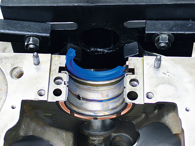
GROOVE the edge of the bearing in the area marked in green as it provides extra lubrication to the bearing where its needed most(the rear support face) that resists the pressure from the clutch and or/torque converter
notice the bearing wears near the edge during the test fit indicating either the bearing is tapered or the bearing or main caps not seated correctly, in any case stop and find out whats causing the problem
http://www.4secondsflat.com/Thrust_bearing_failures.html
http://garage.grumpysperformance.com/index.php?threads/thrust-bearing-wear.619/
http://garage.grumpysperformance.com/index.php?threads/precision-measuring-tools.1390/#post-68861
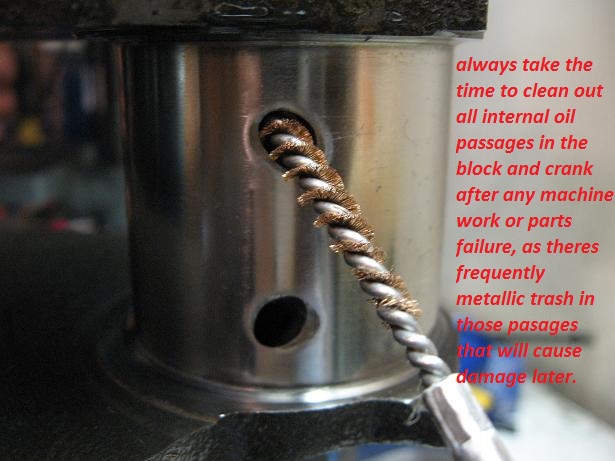
failure to clean out the oil passages in the block and crank journal cross feed oil holes, resulted in trapped debris being flushed out and scoring the bearings during the test fit process in these bearings, an easily avoided but very common screw-up after a cam or bearing fails and your forced to do a ring, cam,lifter, and bearing replacement
just keep in mind that you'll need to very carefully blend and smooth and carefully clean,the edges of the beveled area where the oil port feeds the bearing surface with some 600 grit sand paper so the oil flows well and theres no edges to cause bearing wear issues or crud left from the process that would get embedded in the bearings.

watch this video
http://www.youtube.com/watch?feature=pl ... dEFGJqpCMY

http://www.jensenhealey.com/tech/plasti ... gauge.html
Rod bearings 0.002 - 0.025" , side clearance 0.010 - 0.020"
Main bearings 0.002 - 0.003" for most engines ( 0.020-0.025 bearing clearance on small blocks, .025-.027 bearing clearance is about ideal, on big blocks ), 0.005 - 0.007 crankshaft end play
Piston to head clearance 0.038 MINIMUM including gasket (.038-.042 quench is what you want with steel rods)(steel rods), 0.060" MINIMUM quench aluminum rods
Valve to piston clearance MINIMUM 0.100" exhaust , 0.080" intake NO VALVE FLOAT
Recommended: 0.080 intake, 0.100 Exhaust (steel rods) 0.100 intake, 0.120 Exhaust aluminum rods
TORQUE SPECS CAN BE FOUND HERE IN THIS LINK
viewtopic.php?f=50&t=1222
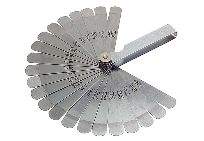
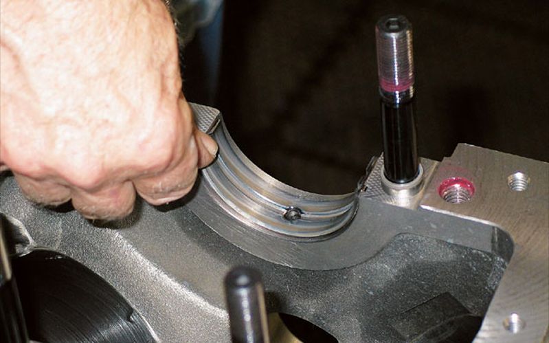
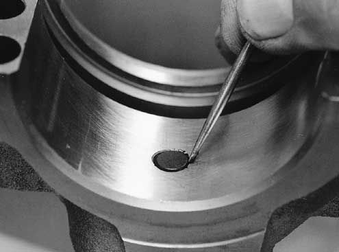
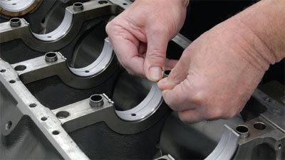
re- check with plasti-gauge during the pre assembly
don,t assume the bearing journal diameters are correct, on any crankshaft,
, ( while they are almost certainly correct on a SCAT crank)
its good practice and certainly smart to measure carefully to be 100% sure, and that youve purchased and matched them to the correct matched bearing set!
btw spray the bearing and the crank surfaces, and the plasti-gauge with WD40 before you measure clearances and it won,t tend to stick as much
http://www.goodson.com/store/template/p ... f3f1075a76
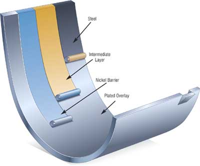
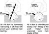
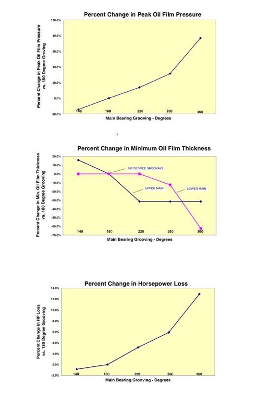
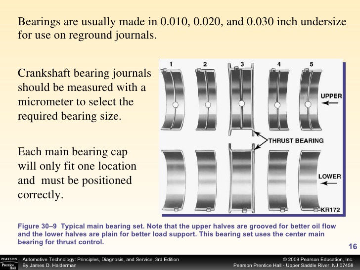
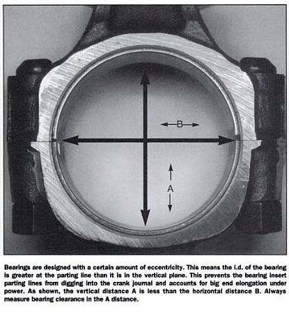
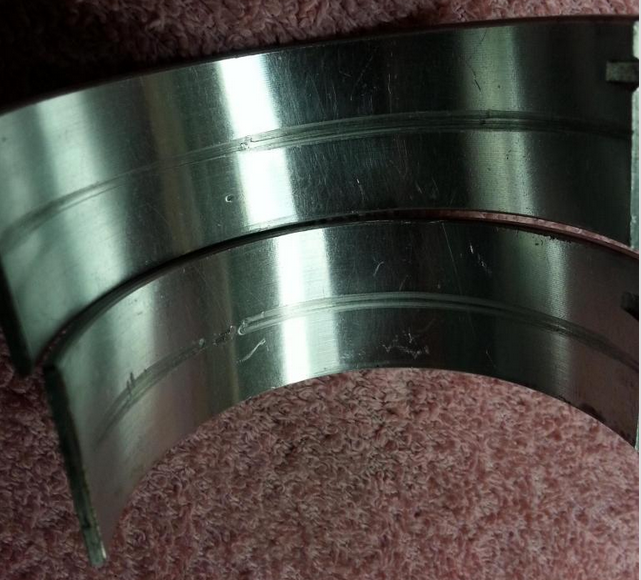
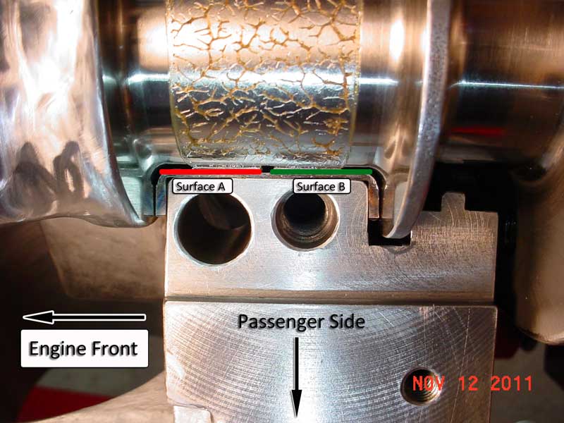
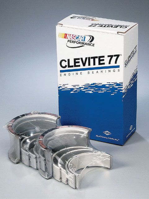
Clevite H-Series main bearings were developed primarily for NASCAR racing, but are well suited to other types of competition engines as well. They're especially good for engines that run at medium-to-high revs. They have steel backings with carefully selected overlays and a high crush factor, plus a medium level of eccentricity. H-Series bearings have enlarged chamfers at the sides for greater crank-fillet clearance and are made without flash plating for better seating. They're also available with either 180 degree or 360 degree oil grooves, as well as an extra 0.001 in. of clearance. the 180 degree groove bearing with only the top 1/2 groove in the block is preferred as having the lower 1/2 in the main cap without the groove, has a higher load capacity
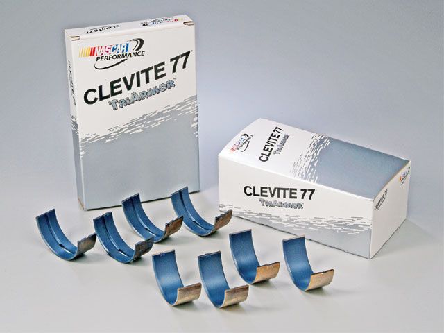
LOOK CLOSELY the upper main bearing, that seats in the block, is grooved the lower half that seats in the main cap is NOT GROOVED
HERES A GREAT DEAL OF INTERESTING RELATED INFO
http://garage.grumpysperformance.com/index.php?threads/main-cap-fit-in-block.5945/#post-18302
http://garage.grumpysperformance.com/index.php?threads/splayed-main-caps.1014/#post-3831
http://garage.grumpysperformance.co...block-cylinder-wall-thickness.976/#post-22976
http://garage.grumpysperformance.com/index.php?threads/sbc-spacer-bearings.3058/
http://www.stealth316.com/misc/clevite-77-rod-main-bearings.pdf
http://garage.grumpysperformance.co...guess-on-clearances-and-journal-surface.9955/
http://garage.grumpysperformance.com/index.php?threads/thrust-bearing-wear.619/
http://engineparts.com/techbulletins/CL77-1-205R.pdf
http://www.stealth316.com/misc/clevite-77-rod-main-bearings.pdf
http://garage.grumpysperformance.com/index.php?threads/can-i-get-it-polished.9214/#post-43456
Main bearings 0.002 - 0.003" for most engines ( 0.020-0.025 bearing clearance on small blocks, .025-.027 bearing clearance is about ideal, on big blocks ), 0.005 - 0.007 crankshaft end play
steelcomp said:On clearances; the industry standard for performance clearances has long time been .001" for every 1" of shaft diameter. For a BB Chev 2.75 main journal, that's .0027" clearance. .0025 is on the tight side and I wouldn't run anything that tight that's going to spin any considerable rpm or or make any considerable power. The more power and rpm you make, the more parts are going to flex and take up the needed space to form an effective oil wedge. Running more clearance than necessary is a little added insurance, but also means more oil volume needed and more free oil flying around in the crankcase, more work for the oil pump, and more windage issues to deal with.
this is rather good advise, but consider the bearing clearance must be checked carefully and verified, and the crank journals must be carefully checked for taper, roundness finish and journals must be concentric
Piston to head clearance 0.038 MINIMUM including gasket (.038-.042 quench is what you want with steel rods)(steel rods), 0.060" MINIMUM quench aluminum rods
Valve to piston clearance MINIMUM 0.100" exhaust , 0.080" intake NO VALVE FLOAT
Recommended: 0.080 intake, 0.100 Exhaust (steel rods) 0.100 intake, 0.120 Exhaust aluminum rods
TORQUE SPECS CAN BE FOUND HERE IN THIS LINK
http://garage.grumpysperformance.com/index.php?threads/torque-specs-calculator-links-etc.1222/
http://garage.grumpysperformance.com/index.php?threads/rotating-assembly-bearings.9527/
together correctly
http://www.harborfreight.com/36-piece-3 ... 60669.html
watch this video
Chevy V8 bore & stroke chart
always accurately measure the crank main journals, and remember the crank and block bearing sizes on a 400 sbc and 350 smc are different as are the early 283-327 sbc
Chevy V8 Crankshaft Journal Sizes
Here's a list of Chevy V-8 crankshaft journal sizes. All journal sizes are given in "STANDARD" sizes. Your crankshaft may have been cut down in size previously by a machine shop. Make sure your crank will work in the block you have. Blocks were made for each crank main journal size. If you are putting a "small" or "medium" journal smallblock crank into a "medium" or "large" journal smallblock block you will need crank bearing "spacers" or use special "thick" bearings available from aftermarket suppliers.
Chevy Smallblock V8 Crankshaft Journal Sizes
Gen.I, "Small Journal"
265...Mains-2.30"-Rods-2.00"
283...Mains-2.30"-Rods-2.00"
302...Mains-2.30"-Rods-2.00"
327...Mains-2.30"-Rods-2.00"
Gen.I, "Medium Journal", includes "Vortec" 305 and 350 thru '98
262...Mains-2.45"-Rods-2.10"
267...Mains-2.45"-Rods-2.10"
302...Mains-2.45"-Rods-2.10"
305...Mains-2.45"-Rods-2.10"
307...Mains-2.45"-Rods-2.10"
327...Mains-2.45"-Rods-2.10"
350...Mains-2.45"-Rods-2.10"
Gen.I, "Large Journal"
400...Mains-2.65"-rods-2.10"
Non-production Gen.I combination, using Gen.I 400 crank in Gen.I 350 block
383...400 crank, Mains cut to 2.45"-Rods-2.10"
Non-production Gen.I combination, using Gen.I 350 crank in Gen.I 400 block
377..."Spacer" or "thick" main bearings with 350 crank-Rods-2.10"
Gen.II, "Medium Journal", includes "L-99" 265, "LT-1" 350, "LT-4" 350
265...Mains-2.45"-rods-2.10"
305...Mains-2.45"-Rods-2.10"
350...Mains-2.45"-Rods-2.10"
Non-production Gen.II combination, using Gen.II 265 "L-99" crank in Gen.II 350 block
302...Mains-2.45"-Rods-2.10"
Gen.III, includes '97-2005 "LS-1" Corvette, Firebird, Camaro
345...Mains-2.558"-Rods-2.10"
Corvette "ZR-1", DOHC, "LT-5"
350...Mains-2.76"-Rods-2.10"
CID BORE STROKE
262 = 3.671" x 3.10" (Gen. I, 5.7" rod)
265 = 3.750" x 3.00" ('55-'57 Gen.I, 5.7" rod)
265 = 3.750" x 3.00" ('94-'96 Gen.II, 4.3 liter V-8 "L99", 5.94" rod)
267 = 3.500" x 3.48" (Gen.I, 5.7" rod)
283 = 3.875" x 3.00" (Gen.I, 5.7" rod)
293 = 3.779" x 3.27" ('99-later, Gen.III, "LR4" 4.8 Liter Vortec, 6.278" rod)
302 = 4.000" x 3.00" (Gen.I, 5.7" rod)
305 = 3.736" x 3.48" (Gen.I, 5.7" rod)
307 = 3.875" x 3.25" (Gen.I, 5.7" rod)
325 = 3.779" x 3.622" ('99-later, Gen.III, "LM7", "LS4 front wheel drive V-8" 5.3 Liter Vortec, 6.098" rod)
327 = 4.000" x 3.25" (Gen.I, 5.7" rod)
345 = 3.893" x 3.622" ('97-later, Gen.III, "LS1", 6.098" rod)
350 = 4.000" x 3.48" (Gen.I, 5.7" rod)
350 = 4.000" x 3.48" ('96-'01, Gen. I, Vortec, 5.7" rod)
350 = 3.900" x 3.66" ('89-'95, "LT5", in "ZR1" Corvette 32-valve DOHC, 5.74" rod)
364 = 4.000" x 3.622" ('99-later, Gen.III, "LS2", "LQ4" 6.0 Liter Vortec, 6.098" rod)
376 = 4.065" x 3.622" (2007-later, Gen. IV, "L92", Cadillac Escalade, GMC Yukon)
383 = 4.000" x 3.80" ('00, "HT 383", Gen.I truck crate motor, 5.7" rod)
400 = 4.125" x 3.75" (Gen.I, 5.565" rod)
427 = 4.125" x 4.00" (2006 Gen.IV, LS7 SBC, titanium rods)
Two common, non-factory smallblock combinations:
377 = 4.155" x 3.48" (5.7" or 6.00" rod)
400 block and a 350 crank with "spacer" main bearings
383 = 4.030" x 3.75" (5.565" or 5.7" or 6.0" rod)
350 block and a 400 crank, main bearing crank journals
cut to 350 size
ALL production big blocks used a 6.135" length rod.
CHEVY BIG BLOCK V-8 BORE AND STROKE
366T = 3.935" x 3.76"
396 = 4.096" x 3.76"
402 = 4.125" x 3.76"
427 = 4.250" x 3.76"
427T = 4.250" x 3.76"
454 = 4.250" x 4.00"
477= 4.5" bore x 3.76" stroke
496 = 4.250" x 4.37" (2001 Vortec 8100, 8.1 liter)
502 = 4.466" x 4.00"
557T= 4.5 bore 4.375" stroke
572T = 4.560" x 4.375" (2003 "ZZ572" crate motors)
T = Tall Deck
ALL production big blocks used a 6.135" length rod.
MEASURE CAREFULLY
http://garage.grumpysperformance.co...ting-resistance-to-look-for.11312/#post-51472
the most important and effective performance asset you have is simply your ability to ask yourself questions, the ability to think logically isolate and test components carefully and doing the research if its required to find the best answer's you'll need.
its the attention to details and checking clearance etc. and time and care taken,
that makes the difference between a barely or average functional ,
and a rather exceptional engine build, yes the urge to get it running is strong,
but getting it done correctly is the goal
Plastic gauge?
Question: Can plastic gauge read correctly if used on a crank already oiled or with assembly lube?? I am wanting to confirm the work done by my machine shop but I do not want to tear it down and dry it off, just see if they did the clearances correctly. I figure to check one or two main caps...
garage.grumpysperformance.com
http://garage.grumpysperformance.co...ting-resistance-to-look-for.11312/#post-51472
yes I use both micrometers and snap gauges and cross check with plasti-gauge
and yes when you compare the crushed width of the plasti-gauge youll find it rarely falls as an exact match to the bar chart tape that is packaged with it so you can judge clearance based on crush width
http://garage.grumpysperformance.com/index.php?threads/bearing-clearances.2726/
failure to take the time and effort to read the sub linked info,
WILL usually result in
significantly increased cost and delays in engine assembly!
yes Ive seen several cases where guys failed to install the oil pump pick-up at the proper minimum 3/8"-to-1/2" off the oil pan floor clearance,
the result is the pump is starved for oil intake flow.
http://garage.grumpysperformance.co...m-sure-your-convinced-its-the-oil-pump.11085/
http://garage.grumpysperformance.co...m-oil-pump-installed-now-no-oil-pressure.525/
http://garage.grumpysperformance.com/index.php?threads/bbc-oil-pump-in-a-sbc.2598/
viewtopic.php?f=53&t=852&p=1311&hilit=checking+bearings#p1311
https://www.fordmuscle.com/fundamentals/plastiguage/
http://www.autozone.com/test-scan-and-s ... 36168_0_0/
http://www.hotrod.com/how-to/additional ... icrometer/
viewtopic.php?f=53&t=9214&p=43456&hilit=plastigauge#p43456
http://video.answers.com/engine-bearing ... s-39414874
http://www.summitracing.com/parts/MEL-10990/?rtype=4
http://www.engineparts.com/techbulletin ... 1-205R.pdf
http://www.stealth316.com/misc/clevite- ... ooving.pdf
http://www.circletrack.com/enginetech/c ... ce_basics/
http://garage.grumpysperformance.co...l-pressure-switch-on-fuel-pump-circuit.16013/
http://www.vsihp.com/library/CleviteEng ... sGuide.pdf
http://www.bracketracer.com/engine/mains/mains.htm
http://cleviteonengine.com/askclevite.asp
http://www.jegs.com/p/Clevite/Clevite-7 ... 4/10002/-1
http://ecatalog.mitutoyo.com/Holtest-Ty ... C1530.aspx
Rod bearings 0.002 - 0.025" , side clearance 0.010 - 0.020"
Main bearings 0.002 - 0.003" for most engines ( 0.020-0.025 bearing clearance on small blocks, .025-.027 bearing clearance is about ideal, on big blocks ), 0.005 - 0.007 crankshaft end play
Stock Bearing Clearances
The general rule of thumb for bearing clearances is 0.0010 inch for every 1 inch of journal diameter. That's true for mains and rods, and applies to almost all engines. For the small-block's 2-inch rod journals, that means 0.002 inch of clearance between the rod journal and bearing, by the rule of thumb. The GM-specified tolerances are 0.002 to 0.0025 inch, which lines up well with the rule. Side clearances come in at 0.010 to 0.020 inch, as specified by GM. The clearance rule applies to most engines, but it's generally best to avoid going below 0.0020 inch on any bearing, regardless of the journal diameter.
YOU ALSO HAVE THE OPTION OF HAVING THE CRANK JOURNALS MICRO POLISHED WHILE REMOVING JUST ENOUGH SURFACE FROM THOSE JOURNALS TO GAIN THE REQUIRED CLEARANCE, IF THE CLEARANCE IS TOO TIGHT
http://garage.grumpysperformance.com/index.php?threads/precision-measuring-tools.1390/#post-68861
WATCH VIDEO most larger machine shops can do that cheaply and gain you the required clearance
Manufacturers are frequently asked what difference grooving makes. Various forms of main bearing grooving have been used over the years.
It’s essential to understand that bearings depend on a film of oil to keep them separated from the shaft surface. This oil film is developed by shaft rotation. As the shaft rotates it pulls oil into the loaded area of the bearing and rides up on this film much like a tire hydroplaning on wet pavement.
Grooving in a bearing acts like tread in a tire to break up the oil film. While you want your tires to grip the road, you don’t want your bearings to grip the shaft, so grooving is bad for maintaining an oil film. The primary reason for having any grooving in a main bearing is to provide oil to the connecting rods. Without rod bearings to feed, a simple oil hole would be sufficient to lubricate a main bearing.
Many early engines used full grooved bearings and some even used multiple grooves. Those choices were based on what engineers knew at the time. As engine and bearing technology developed, the negative effect of grooving was recognized and bearing grooving was removed from modern lower main bearings. The result is in a thicker film of oil for the shaft to ride on.
This provides a greater safety margin and improved bearing life. Upper main shells, which see lower loads than the lowers, and hence don’t apply the same load to the oil film, have retained a groove to supply the connecting rods with oil.
In an effort to develop the best possible main bearing designs for high performance engines, manufacturers have investigated the effects of main bearing grooving on bearing performance. The graphs (Figure 1) illustrate that a simple 180° groove in the upper main shell is still the best overall design.
While a slightly shorter groove of 140° provides a marginal gain, most of the benefit is to the upper shell, which doesn’t need improvement. On the other hand, extending the groove into the lower half, even as little as 20° at each parting line (220° in total), takes away from upper bearing performance without providing any benefit to the lower half. It’s also interesting to note that as groove length increases so does horsepower loss and peak oil film pressure, which is transmitted directly to the bearing.
Notes: You will still find some full-grooved main sets offered for older engines where demand is low and the engineering cost to bring the sets to current standards is not warranted (bearings generally represent the technology of the time the engine was developed).
http://www.stockcarracing.com/techartic ... ewall.html
http://www.goodson.com/store/template/p ... f3f1075a76
http://www.chevyhiperformance.com/tech/ ... index.html
http://www.circletrack.com/tipstricks/4 ... index.html
http://www.carcraft.com/techarticles/cc ... _tips.html
http://www.hotrod.com/techarticles/engi ... index.html
http://www.engineparts.com/techbulletin ... 1-205R.pdf
http://www.engineersedge.com/lubrication/molybdenum_disulfide_characteristics.htm
when assembling any engines valve train component parts and bearing surfaces,should be carefully cleaned and soaked with moly spray and then coated with moly assembly lube prior to assembly, Moly exists as microscopic hexagonal crystal platelets Several molecules make up one of these platelets. A single molecule of Moly contains two sulfur atoms and one molybdenum atom. Moly platelets are attracted to metal surfaces. This attraction and the force of moving engine parts rubbing across one another provide the necessary thermochemical reaction necessary for Moly to form an overlapping protective coating like armor on all of your engine parts. This protective armor coating has a number of properties that are very beneficial for your engine.
The Moly platelets that make up the protective layers on your engine surfaces slide across one another very easily. Instead of metal rubbing against metal, you have Moly platelets moving across one another protecting and lubricating the metal engine parts.
This coating effectively fills in the microscopic pores that cover the surface of all engine parts, making them smoother. This feature is important in providing an effective seal on the combustion chamber. By filling in the craters and pores Moly improves this seal allowing for more efficient combustion and engine performance.
This overlapping coating of Moly also gives protection against loading (perpendicular) forces. These forces occur on the bearings, and lifters. The high pressures that occur between these moving parts tend to squeeze normal lubricants out.
http://www.carbideselect.com/burshpescuts.php
Ive generally found the H-series bearings are the best choice, remember most after market cranks have beveled crank journals requiring matched beveled edge (H) style bearing inserts, standard bearings will have the edge of the bearing insert bind on the radias edge
in a properly set up block a pressurized oil film supports the cam and main bearings
http://carcraft.automotive.com/66890/cc ... -tips.html
bearings AND connecting rods have an inner facing side and outer side the inner side facing the matching rod has far less edge clearance because they don,t need the radias that is required for the edge of the crank journals
IVE dunked my piston/ring assembly's in a can of MARVEL MYSTERY OIL just before installation with a ring compressor and have never seen the slightest indication of problems either on ring sealing getting the rings broken in, or on tearing the engines down later for inspections the amounts not that great, ideally each one installed adds a bit of resistance but at no time should the short block take over 40 ft lbs ABSOLUTE MAXIMUM to start it spinning,and LESS than 20 lbs to keep it moving, even with all the rings and pistons installed,yes you need to verify the bearing clearances during assembly and IT SHOULD take between 20lbs-25 lbs to start it spinning if the clearances are correct! and LESS than 20 lbs to keep it moving
IF it takes over 40 ft lbs to get it rotating ,youll need too DISASSEMBLE and FIND OUT WHY!
http://www.engineprofessional.com/TB/EPQ410_10-18.pdf
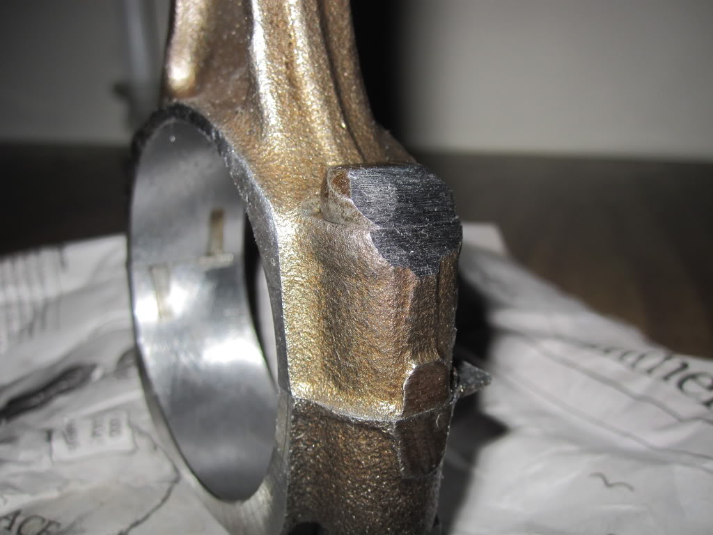
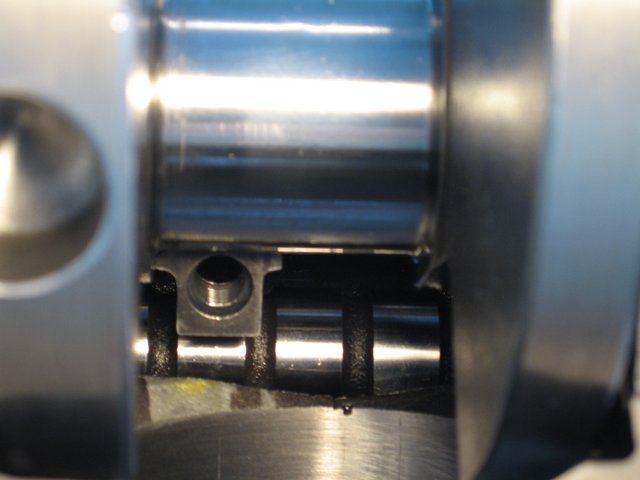
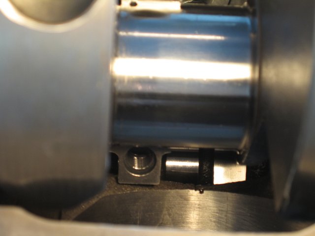
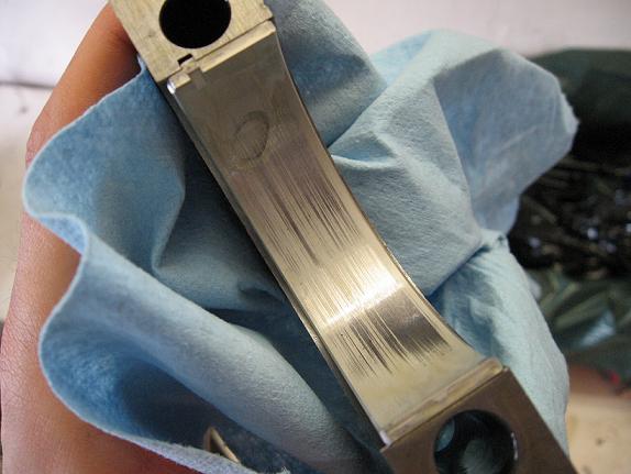
when you get the crank polished take the time and effort to clean out any cross drill oil feed passages and to very carefully de-burr the passage opening edges, as this is a very commonly overlooked issue, below is what at first looks like a perfectly polished crank, with oil feed passages to the rod bearings, but the deep scratches the oil feed passage openings left in the rod bearing surfaces bare witness, after a single rotation, during a trial assembly show they are HARDLY burr free or ready for use, and obviously he failed to check each rod bearing during the assembly process, and probably ignored , what was very likely un-even or rather excessive resistance to the crank rotation. which should never exceed about 40 ft lbs even with all 8 rod bearings and pistons installed
having the correct bearing clearances are critical, to durability, generally you'll want no less than .0022-.0025 with .0025-.0028 preferred for most performance use. I prefer .0025-.0028 most of the time
Both rods & mains.
Bearing Tips And Tricks
1. Always check your micrometer with a standard before measuring.
2. Always use the same micrometer for the journals and to set the inside mic diameter.
3. Torque the rods and mains to spec before measuring a bearing inside diameter.
4. Changing rod bolts or moving from bolts to studs in the main caps will affect bearing clearance.
5. Temperature will affect the accuracy of the micrometer and the size of journal diameters both inside and out.
6. If you have one tight and one loose rod-bearing combination, try switching the bearings between the two. We've seen this work several times when the clearances are just a little bit off.
7. Never mix different bearing families when customizing bearing clearance. If you are using Federal-Mogul coated bearings, don't mix in a half shell uncoated race bearing.
http://www.robertpowersmotorsports.com/Tech2.html
http://www.stockcarracing.com/techartic ... index.html
http://mechdb.com/index.php/Plastigagin ... clearances
from chevy high performance mag
MORE USEFUL INFO
BE 100% SURE that the oil pump bolt or STUD doesn,t protrude past the inner main cap surface , because if it bears on the rear main bearing shell it will almost always result in a quickly failed rear bearing
failure to use the correct stud, bolt or nut or check clearances when mounting an oil pump can cause problems
ONE RATHER COMMON MISTAKE IS USING THE WRONG OIL PUMP STUD OR BOLT TO MOUNT THE OIL PUMP AS IF EITHER EXTENDS THRU THE REAR MAIN CAP IT CAN AND WILL BIND ON THE BEARING AND LOCK OR RESTRICT, SMOOTH ROTATION
watch this video
http://www.summitracing.com/parts/MEL-10778/?rtype=4
use plasti-gauge across the whole bearing as you can have a tapered journal that's correct in one area but loose or tight else-ware
GROOVE the edge of the bearing in the area marked in green as it provides extra lubrication to the bearing where its needed most(the rear support face) that resists the pressure from the clutch and or/torque converter
notice the bearing wears near the edge during the test fit indicating either the bearing is tapered or the bearing or main caps not seated correctly, in any case stop and find out whats causing the problem
http://www.4secondsflat.com/Thrust_bearing_failures.html
http://garage.grumpysperformance.com/index.php?threads/thrust-bearing-wear.619/
http://garage.grumpysperformance.com/index.php?threads/precision-measuring-tools.1390/#post-68861
failure to clean out the oil passages in the block and crank journal cross feed oil holes, resulted in trapped debris being flushed out and scoring the bearings during the test fit process in these bearings, an easily avoided but very common screw-up after a cam or bearing fails and your forced to do a ring, cam,lifter, and bearing replacement
just keep in mind that you'll need to very carefully blend and smooth and carefully clean,the edges of the beveled area where the oil port feeds the bearing surface with some 600 grit sand paper so the oil flows well and theres no edges to cause bearing wear issues or crud left from the process that would get embedded in the bearings.
watch this video
http://www.youtube.com/watch?feature=pl ... dEFGJqpCMY
http://www.jensenhealey.com/tech/plasti ... gauge.html
Rod bearings 0.002 - 0.025" , side clearance 0.010 - 0.020"
Main bearings 0.002 - 0.003" for most engines ( 0.020-0.025 bearing clearance on small blocks, .025-.027 bearing clearance is about ideal, on big blocks ), 0.005 - 0.007 crankshaft end play
Piston to head clearance 0.038 MINIMUM including gasket (.038-.042 quench is what you want with steel rods)(steel rods), 0.060" MINIMUM quench aluminum rods
Valve to piston clearance MINIMUM 0.100" exhaust , 0.080" intake NO VALVE FLOAT
Recommended: 0.080 intake, 0.100 Exhaust (steel rods) 0.100 intake, 0.120 Exhaust aluminum rods
TORQUE SPECS CAN BE FOUND HERE IN THIS LINK
viewtopic.php?f=50&t=1222
re- check with plasti-gauge during the pre assembly
don,t assume the bearing journal diameters are correct, on any crankshaft,
, ( while they are almost certainly correct on a SCAT crank)
its good practice and certainly smart to measure carefully to be 100% sure, and that youve purchased and matched them to the correct matched bearing set!
btw spray the bearing and the crank surfaces, and the plasti-gauge with WD40 before you measure clearances and it won,t tend to stick as much
http://www.goodson.com/store/template/p ... f3f1075a76
Clevite H-Series main bearings were developed primarily for NASCAR racing, but are well suited to other types of competition engines as well. They're especially good for engines that run at medium-to-high revs. They have steel backings with carefully selected overlays and a high crush factor, plus a medium level of eccentricity. H-Series bearings have enlarged chamfers at the sides for greater crank-fillet clearance and are made without flash plating for better seating. They're also available with either 180 degree or 360 degree oil grooves, as well as an extra 0.001 in. of clearance. the 180 degree groove bearing with only the top 1/2 groove in the block is preferred as having the lower 1/2 in the main cap without the groove, has a higher load capacity
LOOK CLOSELY the upper main bearing, that seats in the block, is grooved the lower half that seats in the main cap is NOT GROOVED
HERES A GREAT DEAL OF INTERESTING RELATED INFO
http://garage.grumpysperformance.com/index.php?threads/main-cap-fit-in-block.5945/#post-18302
http://garage.grumpysperformance.com/index.php?threads/splayed-main-caps.1014/#post-3831
http://garage.grumpysperformance.co...block-cylinder-wall-thickness.976/#post-22976
Plastic gauge?
Question: Can plastic gauge read correctly if used on a crank already oiled or with assembly lube?? I am wanting to confirm the work done by my machine shop but I do not want to tear it down and dry it off, just see if they did the clearances correctly. I figure to check one or two main caps...
garage.grumpysperformance.com
http://garage.grumpysperformance.com/index.php?threads/sbc-spacer-bearings.3058/
http://www.stealth316.com/misc/clevite-77-rod-main-bearings.pdf
http://garage.grumpysperformance.co...guess-on-clearances-and-journal-surface.9955/
http://garage.grumpysperformance.com/index.php?threads/thrust-bearing-wear.619/
http://engineparts.com/techbulletins/CL77-1-205R.pdf
http://www.stealth316.com/misc/clevite-77-rod-main-bearings.pdf
http://garage.grumpysperformance.com/index.php?threads/can-i-get-it-polished.9214/#post-43456
Last edited by a moderator: