this infos bound to be helpful at times
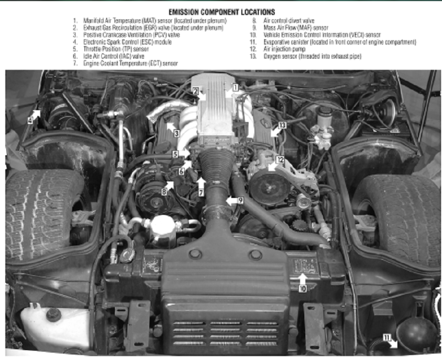
READ THE THREAD THRU TO THE END AND BE AWARE IT, AND ALL OTHER THREADS ARE CONSTANTLY UPDATED WITH NEW LINKS AND INFO
without testing you simply guessing
never guess, deal in verified FACTS!
guessing is a waste of time
think logically, isolate and test
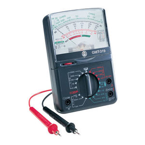
yes IM aware some guys would rather dig out their eye with a red hot fork than to read links, but if you take the time to actually research,pull the trouble codes and READ THRU the shop manual and, use diagnostic tools. like code scanners, and multi meter,timing lights, vacuum gauges etc,..... before jumping into "fixing" problems. in most cases youll find its far faster and easier to locate and correct the problem.
LOOK FOR LOOSE OR CORRODED ELECTRICAL WIRING CONNECTORS, in THE WIRING HARNESS, and VERIFY YOUR FIRING ORDER, YEAH I KNOW YOUR SURE ITS CORRECT, CHECK IT CAREFULLY AGAIN, YOUR NOID TEST LIGHT AND MULTI- METER CAN SAVE YOU A GREAT DEAL OF PROBLEMS AND SCRATCHING YOUR HEAD IF YOU TEST BASIC ELECTRICAL CONNECTIONS< RESISTANCE AND VOLTAGE, CHECK YOUR SENSORS AND GROUNDS, A SHOP MANUALS MANDATORY, HEAT SENSORS AND IGNITION MODULES AND OIL PRESSURE SENSORS HAVE A LONG TRACK RECORD OF FAILING OR PARTIALLY AND INTERMITTENTLY NOT FUNCTIONING
IM JUST CURIOUS?
how many of you gentlemen go to a computer, print out related wiring diagrams ,get out a multi meter and a shop manual and actually read the shop manual, and step thru the indicated testing procedures? check for voltage ohms resistance, loose connections, etc. and have actually used the shop manual, multi meter and printed wiring diagrams ans instructions to isolate and solve a problem on your car?
https://www.corvettecentral.com/c4-84-96/96-shop-service-manual-cd-rom-114143?returnurl=/c4-84-96/?count=9
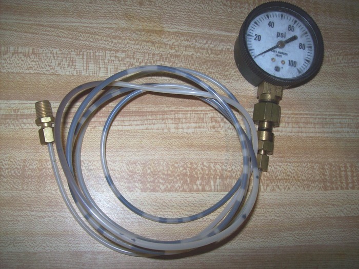
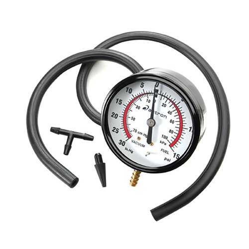
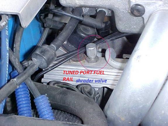
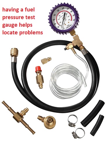
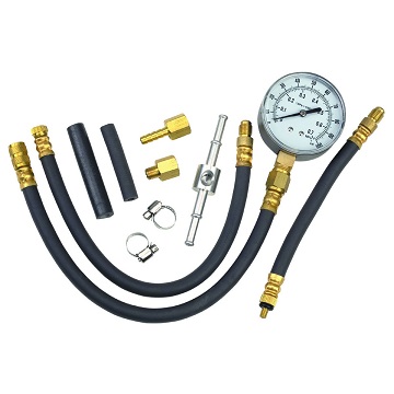
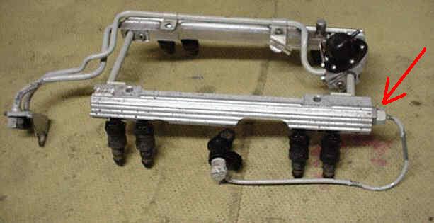
if you have at lease 38 psi in the fuel rail, and it holds at or near at least 38 psi for at least a couple minutes after you stop cranking the engine, the fuel pressure regulator is most likely functioning correctly, but you state the injectors are not squirting fuel and the pump keeps running while you crank the engine?
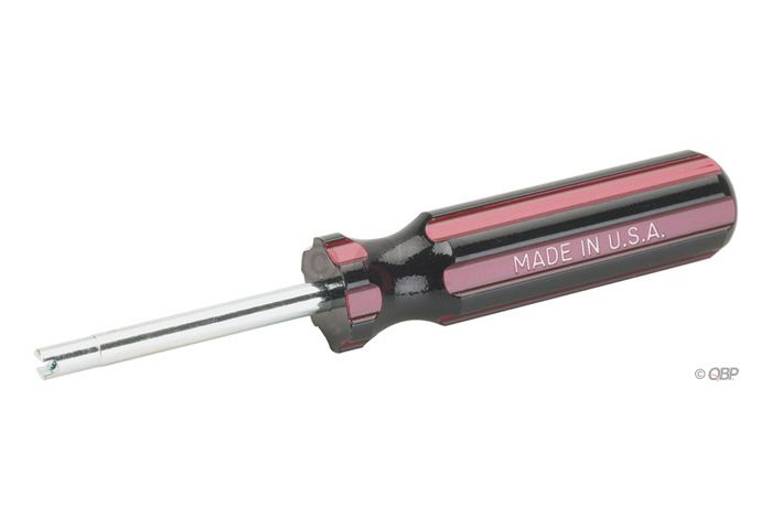
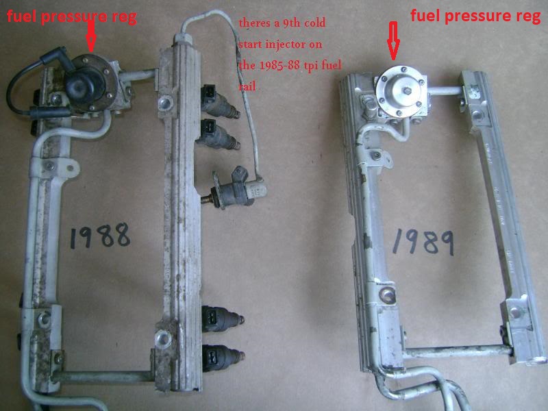
you can test the electrical connectors on the injectors with a noid test light to watch the electric pulse,at each injector location, ID verify timing injector resistance,and check for vacuum leaks while testing, and remember theres a 9th cold start injector on the 1985-88 TPI fuel rail
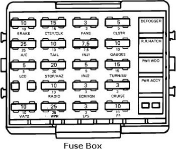
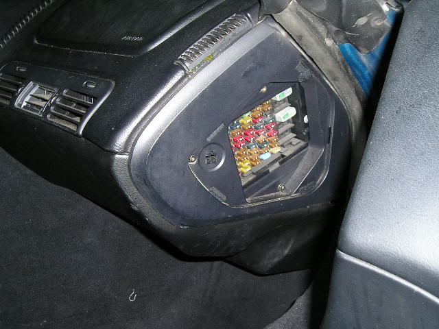
first check your shop manual for the fuse and fuse able link locations
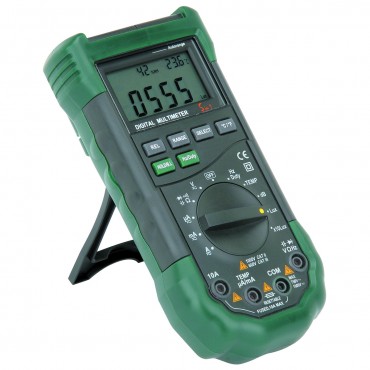
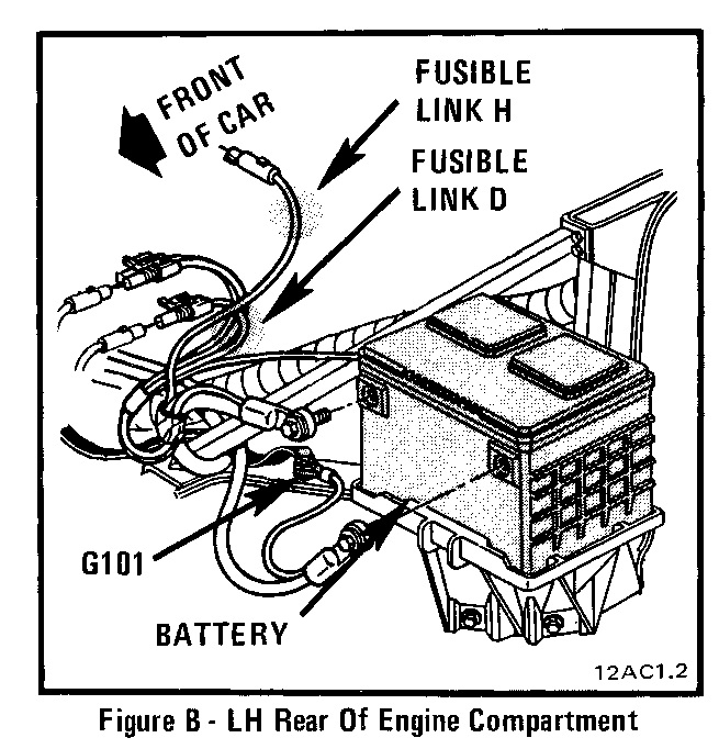
fuses are located in several locations and fuse-able links near the battery, NOW GET A MULTI METER AND CHECK ALL THE FUSES , AND GROUNDS AND BATTERY VOLTAGE AND ELECTRICAL CONNECTIONS LIKE BATTER CABLES AND SENSOR WIRE CONNECTIONS, BECAUSE A SURPRISING NUMBER OF PROBLEMS ON OLDER CORVETTES AND MUSCLE CARS ARE RELATED TO BLOWN FUZES, LOOSE OR CORRODED CONNECTORS, AND BAD BATTERY CONNECTION CABLES OR WEAL BATTERY'S OR DEFECTIVE ALTERNATORS
HERES A FEW USEFUL, related bit of info and LINKS YOU MIGHT WANT TO LOOK THRU
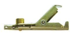
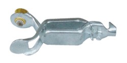
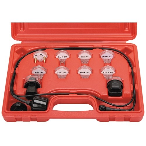
and yes they should all read very closely) then you need a noid kit for a G.M. fuel injection system, these are basically little lights that light as the injector pulse hits them that you plug into the injector harness,after you remove the harness from the injectors, they plug into the harness just like an injector, if you try to start the engine and they blink on and off the pulse is reaching the injectors thus proving that the injectors get the pulse, each injector should get a pulse and you should see each noid light flash, if you don,t theres an electrical or wiring issue, that must be addressed.
injectors normal state is CLOSED they open only with a electric pulse, the duration of the pulse controls the volume of fuel flow
carefully visually inspect your cars wire harness for corrosion ,loose or broken or shorting connectors or wiring, obviously getting the wrong electrical pulse, a grounded or shorted connector will cause problems.
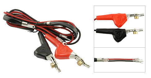
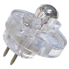
a NOID light can be used to test, the pulse is intermittent if plugged into the cars wire harness and its more likely the injector needs cleaning

http://www.harborfreight.com/11-piece-n ... 97959.html
set up a multi meter like this and pull fuses one at a time to locate shorted circuits
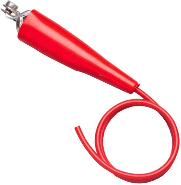
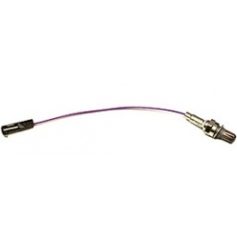
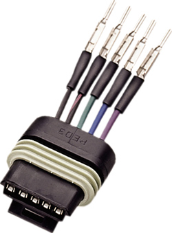
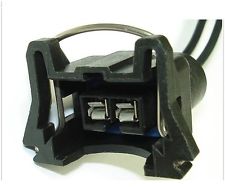
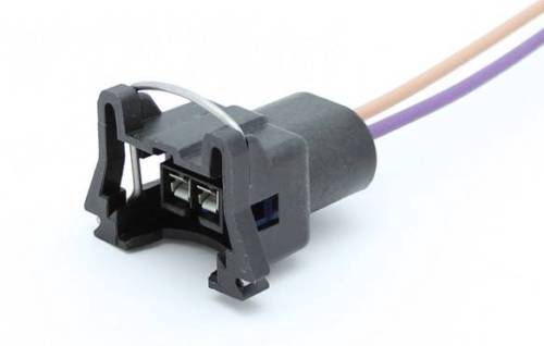
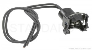
replacement injector pig tails are available at rock auto for less than $5 each
read these links and
related sub links
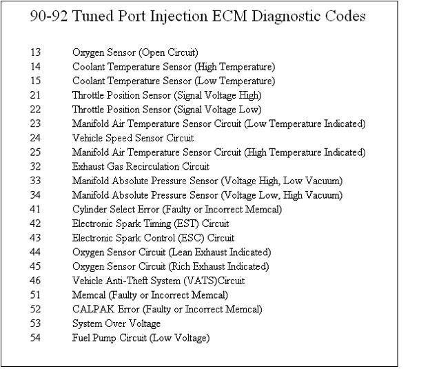
pull trouble codes
http://garage.grumpysperformance.co...oven-facts-if-your-in-doubt.13051/#post-84695
http://forum.grumpysperformance.com/viewtopic.php?f=32&t=1401&p=8895&hilit=start+sequence#p8895
http://garage.grumpysperformance.com/index.php?threads/c4-c5-corvette-trouble-codes.2697/
http://garage.grumpysperformance.com/index.php?threads/lots-of-wiring-info-diagrams.317/#post-83877
http://garage.grumpysperformance.com/index.php?threads/adjusting-your-tps-and-iac.168/
http://garage.grumpysperformance.com/index.php?threads/multi-meters.3110/#post-71867
http://garage.grumpysperformance.com/index.php?threads/1990-corvette-no-spark.13857/#post-70888
http://garage.grumpysperformance.com/index.php?threads/diagnoseing-tpi-lt1-problems.1241/
reading links and sub links can help
replacement connectors and pigtails are available
http://garage.grumpysperformance.com/index.php?threads/lots-of-wiring-info-diagrams.317/#post-83877
http://garage.grumpysperformance.co...-auto-elecrtrical-connectors.3105/#post-68805
http://garage.grumpysperformance.co...cting-a-distributor-for-your-application.855/
http://garage.grumpysperformance.co...-idles-and-sometimes-stalls.10688/#post-46397
viewtopic.php?f=36&t=3105&p=8272&hilit=connectors+pigtails#p8272
viewtopic.php?f=32&t=168&p=41767&hilit=connectors+pigtails#p41767
http://garage.grumpysperformance.co...lay-switch-locations-and-info.728/#post-17654
reading thru a few links might be helpful
step #1
always ISOLATE AND VERIFY, TEST EVERYTHING ASSUME NOTHING!
IF YOU skip the links and you'll miss a good deal of useful info
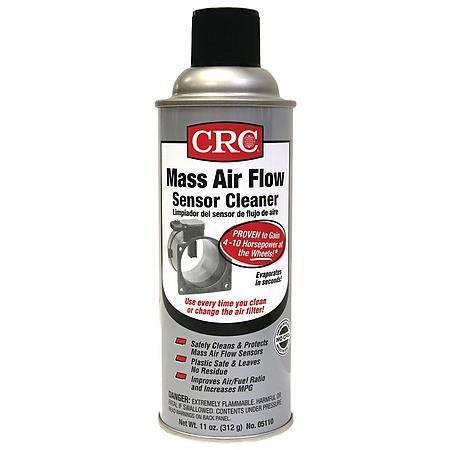
ANY TIME YOU SUSPECT FUEL INJECTOR OR FUEL SYSTEM RELATED ISSUES ,A REASONABLE START POINT IS TO USE A GOOD QUALITY FUEL INJECTION CLEANER ADDITIVE IN THE FUEL TANK AND SWAP TO A NEW FUEL FILTER
http://www.bgprod.com/catalog/gasoline- ... m-cleaner/
http://www.bgprod.com/catalog/gasoline- ... m-cleaner/
AND YES AMAZINGLY, ACTUALLY READING THRU THE POSTED LINKS AND SUB LINKS might help
http://www.chevythunder.com/fuel%20inje ... pg%20B.htm
http://www.mainstreamtopics.com/forums/ ... iagnostic/
http://www.mamotorworks.com/corvette-c4 ... -6128.html
http://garage.grumpysperformance.co...start-right-back-up-and-run.10739/#post-46893
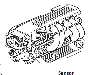
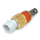
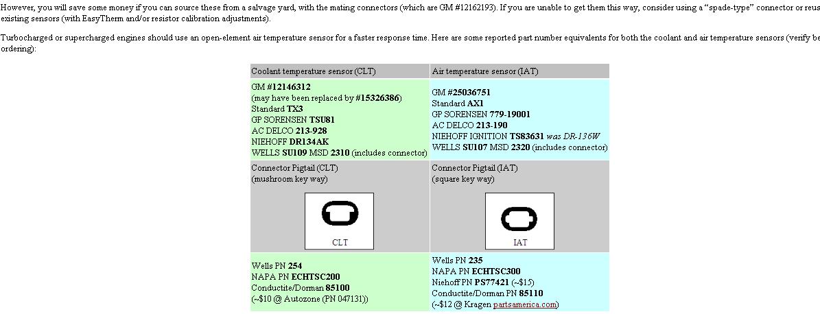
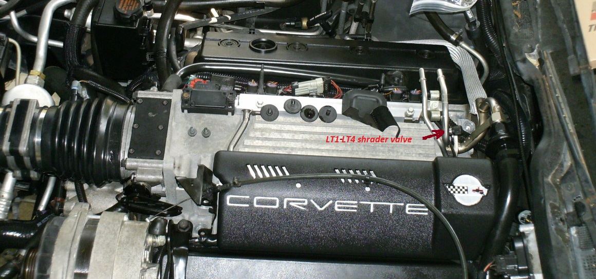
Intake Air Temp sensor. It is located on the bottom of the inlet plenum a few inches ahead of the distributor. It is like right next to the fuel pressure regulator., it can effect fuel flow rates
If your experiencing intermittent electrical issues you will obviously need to get out the shop manual for your year corvette, a multi meter and do some isolate and testing, but be aware that loose or corroded connections , will be hard to isolate, as they seldom present a consistent, solid open or dead short in the wire,theres several electrical connector plugs that connect thru the firewall near the battery location that are subject to corrosion issues and frame grounds that might be suspect, obviously theres sensors that can be defective.
links with lots of sub-links that should be useful, most guys ,faced with isolating an electrical issue, seem to get over whelmed, but if you get out the schematics, use a multi meter and some logic in tracing the circuits, and start pulling fuses and measuring resistance and voltage, take the time to read the manual ,pull trouble codes,and if required get a scan tool or a data logging program for your lap top computer, and using the shop manual, you can generally isolate the cause
http://forum.grumpysperformance.com/viewtopic.php?f=80&t=728&p=9217&hilit=+sensors+location#p9217
http://forum.grumpysperformance.com/viewtopic.php?f=32&t=1401&p=39419&hilit=+sensors+location#p39419
http://forum.grumpysperformance.com/viewtopic.php?f=32&t=2697&p=29270&hilit=+sensors+location#p29270
viewtopic.php?f=50&t=8136&p=28980&hilit=scan+tool#p28980
viewtopic.php?f=27&t=3096&p=18612&hilit=scan+software#p18612
viewtopic.php?f=44&t=758&p=1087&hilit=opti+crap#p1087
http://forum.grumpysperformance.com/viewtopic.php?f=32&t=1401
http://forum.grumpysperformance.com/viewtopic.php?f=32&t=168
viewtopic.php?f=2&t=3074&p=8144#p8144
viewtopic.php?f=36&t=3222&p=8575&hilit=test+alternator#p8575
viewtopic.php?f=70&t=3504&p=9220#p9220
viewtopic.php?f=36&t=8493&p=29779#p29779
viewtopic.php?f=44&t=3401&p=8972&hilit=test+alternator#p8972
viewtopic.php?f=55&t=1241&p=3037&hilit=test+alternator+coil+test#p3037
viewtopic.php?f=50&t=609&p=810&hilit=test+alternator+coil+test#p810
http://forum.grumpysperformance.com/viewtopic.php?f=32&t=596
http://scehovic.angelfire.com/C4starts.html
http://forum.grumpysperformance.com/viewtopic.php?f=70&t=4683
http://shbox.com/1/component_location_views.html
http://www.smogtips.com/trouble-codes.cfm
http://www.aa1car.com/library/us796obd.htm
viewtopic.php?f=57&t=2538&p=6984#p6984
viewtopic.php?f=32&t=2697&p=6985#p6985
viewtopic.php?f=36&t=768&p=2394&hilit=+manual#p2394
viewtopic.php?f=36&t=520&p=645&hilit=vats+resistor#p645
don,t get over whelmed,
simply break the problem down to testing each basic sub system,
test each related sensor and electrical component and electrical sensor and connection.
some reading on the threads posted below, a bit of logic and deductive reasoning, and a multi meter and a shop manual will go a long way toward finding and fixing the problem.
Measured Value
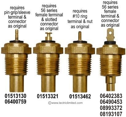
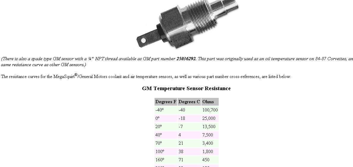
Engine Coolant Temperature Sensor. 185 Ohms @ 210F, 3400 Ohms @ 68F, 7,500 Ohms @ 39 F.
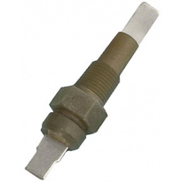
Engine Oil Temperature Sensor. 185 Ohms @ 210 F, 3400 Ohms @ 68 F, 7,500 Ohms @39 F.
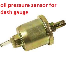
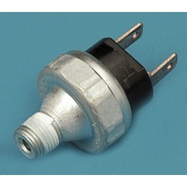
Oil Pressure Sender/Switch. 1 Ohms @ 0 PSI, 43 Ohms @ 30 PSI, 86 Ohms @ 60 PSI.
Fuel Quantity Sender. 0 Ohms @ Empty, 45 Ohms @ 1/2 Full, 90 Ohms @ Full.
MAT (Manifold Absolute Temperature Sensor). 185 Ohms @ 210 F, 3400 Ohms @ 70 F, 15,000 Ohms @ 40 F.
Outside Temperature Sensor. 4400 Ohms @ 60 F, 2200 Ohms @ 85 F.
In Car Temp Temperature Sensor. 4400 Ohms @ 60 F, 2200 Ohms @ 85 F.
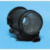
MAF (Mass Air Flow) Sensor. .4 Volts @ idle, 5 Volts @ Full Throttle.
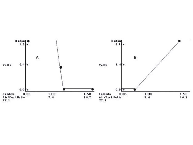
Oxygen (O2) Sensor. .1 Volt Lean Mixture, .9 Volt Rich Mixture.
TPS (Throttle Position Sensor). .54 Volts Idle, ~ 5 Volts Full Throttle.
Sensor Locations
Sensor
Location
Engine Coolant Temperature Sensor. Front of engine, below Throttle Body.
Engine Oil Temperature Sensor. Left rear of engine, just above the oil filter.
Oil Pressure Sender/Switch. Top, left hand rear of engine.
Fuel Quantity Sender. Top of fuel tank, beneath filler pipe escutcheon panel.
MAT (Manifold Absolute Temperature Sensor). Underside of manifold air plenum at rear.
Outside Temperature Sensor. Right side of engine, top right corner of radiator.
In Car Temp Temperature Sensor. Coupe: above left seat near interior courtesy light, Convertible: center of cargo compartment lid.
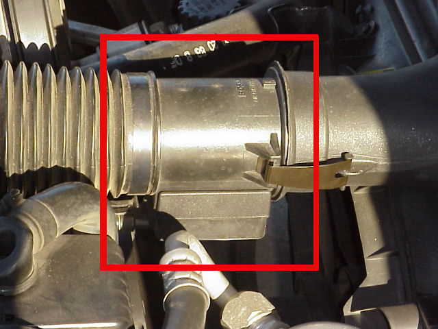
MAF (Mass Air Flow) Sensor. Front of engine ahead of throttle body.
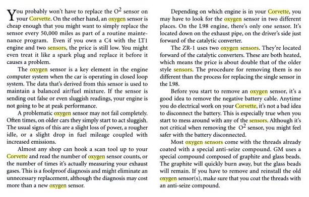
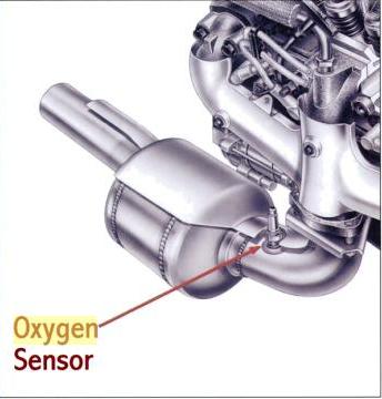
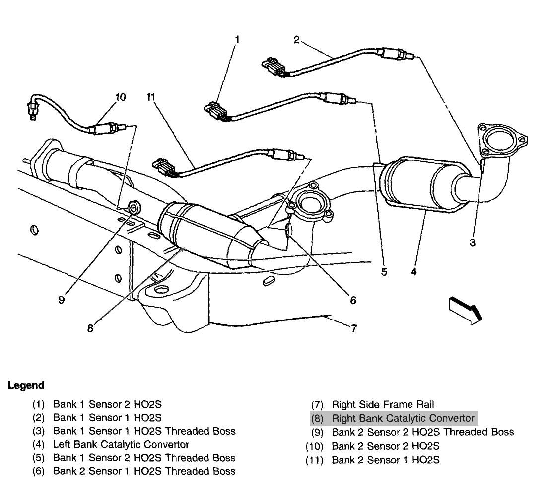
Oxygen (O2) Sensor. Left side of engine, in exhaust pipe.
TPS (Throttle Position Sensor). Right side of throttle body at the front.
sensor locations
knowing whats going on and WHY can help
http://www.corvettefever.com/techarticl ... index.html
http://members.shaw.ca/corvette86/Component Location View 86.pdf
http://members.shaw.ca/corvette86/FuelSystemDiagnosis.pdf
http://www.summitracing.com/parts/HYP-4026/
http://www.summitracing.com/parts/HDA-3653/
Sensor
Location
Engine Coolant Temperature Sensor. Front of engine, below Throttle Body.
Engine Oil Temperature Sensor. Left rear of engine, just above the oil filter.
viewtopic.php?f=54&t=1396&p=3221&hilit=+switch#p3221
Oil Pressure Sender/Switch. Top, left hand rear of engine.
Fuel Quantity Sender. Top of fuel tank, beneath filler pipe escutcheon panel.
MAT (Manifold Absolute Temperature Sensor). Underside of manifold air plenum at rear.
Outside Temperature Sensor. Right side of engine, top right corner of radiator.
In Car Temp Temperature Sensor. Coupe: above left seat near interior courtesy light, Convertible: center of cargo compartment lid.
MAF (Mass Air Flow) Sensor. Front of engine ahead of throttle body.
http://tpiparts.net/85_89_maf_sensors/
Oxygen (O2) Sensor. Left side of engine, in exhaust pipe.(some years have two ,one on both sides)
TPS (Throttle Position Sensor). Right side of throttle body at the front.
Sensor Outputs:
Sensor
Measured Value
Engine Coolant Temperature Sensor. 185 Ohms @ 210F, 3400 Ohms @ 68F, 7,500 Ohms @ 39 F.
Engine Oil Temperature Sensor. 185 Ohms @ 210 F, 3400 Ohms @ 68 F, 7,500 Ohms @39 F.
Oil Pressure Sender/Switch. 1 Ohms @ 0 PSI, 43 Ohms @ 30 PSI, 86 Ohms @ 60 PSI.
Fuel Quantity Sender. 0 Ohms @ Empty, 45 Ohms @ 1/2 Full, 90 Ohms @ Full.
MAT (Manifold Absolute Temperature Sensor). 185 Ohms @ 210 F, 3400 Ohms @ 70 F, 15,000 Ohms @ 40 F.
Outside Temperature Sensor. 4400 Ohms @ 60 F, 2200 Ohms @ 85 F.
In Car Temp Temperature Sensor. 4400 Ohms @ 60 F, 2200 Ohms @ 85 F.
MAF (Mass Air Flow) Sensor. .4 Volts @ idle, 5 Volts @ Full Throttle.
Oxygen (O2) Sensor. .1 Volt Lean Mixture, .9 Volt Rich Mixture.
TPS (Throttle Position Sensor). .54 Volts Idle, ~ 5 Volts Full Throttle.

IAC and TPS Adjustment
http://www.thirdgen.org/tpimod2
TPI Injector Swap
http://www.thirdgen.org/injectorswap
Throttle Body Coolant Bypass
http://www.thirdgen.org/coolantbypass
http://www.jcwhitney.com/autoparts/Sear ... p=ZX503796
http://www.summitracing.com/parts/SUN-CP9001
http://www.etoolcart.com/autoxray-scann ... x6000.aspx
viewtopic.php?f=32&t=304
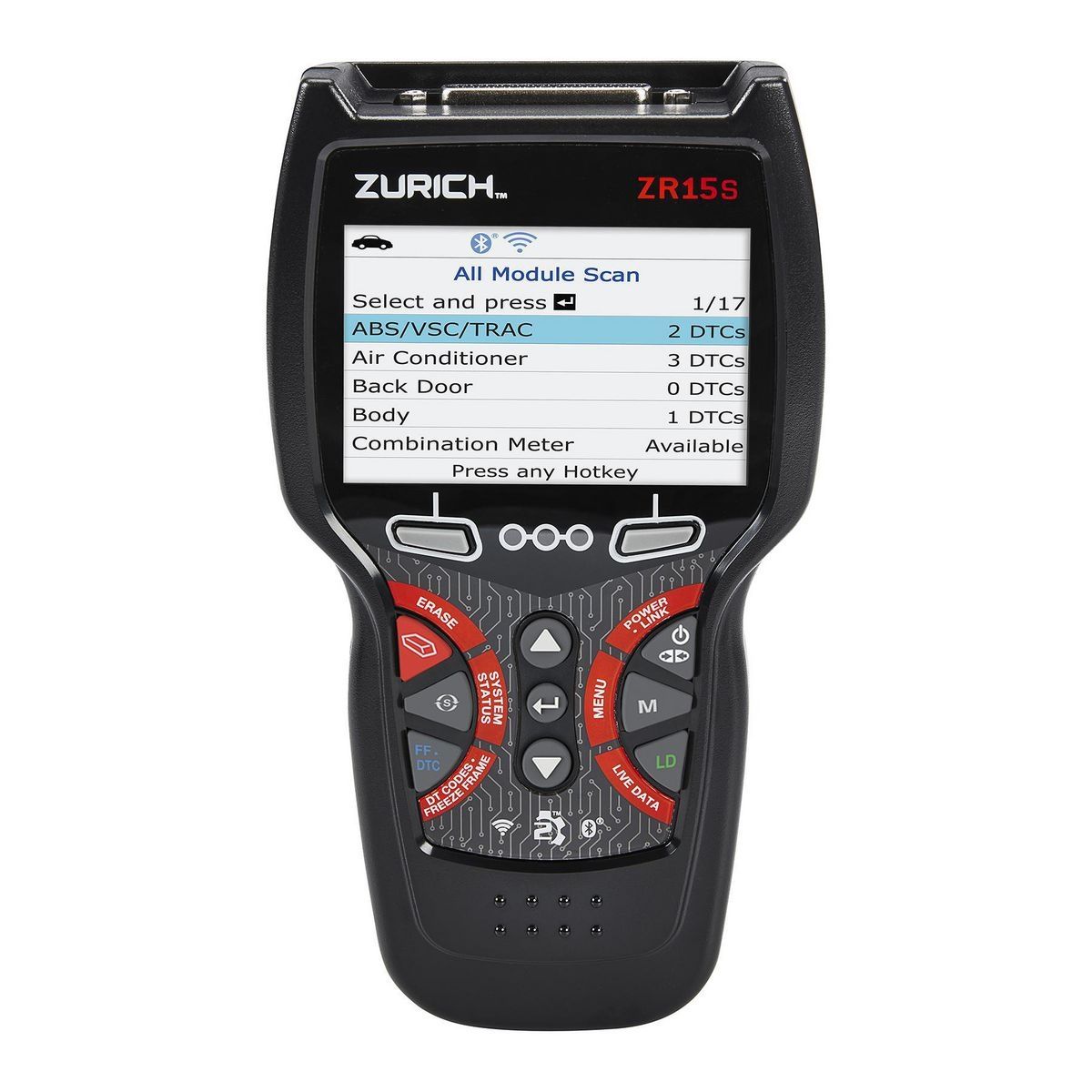
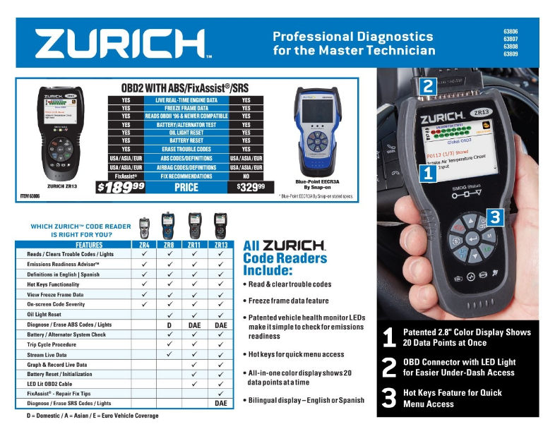
ID also suggest buying a diagnostic tool, with real time data logging to a lap top computer, and your shop manual, it helps isolate problems, ignition spark should be bright blue and impressive, if its, weak,narrow, yellow or red theres a problem so research the cause, verify the coil and voltage
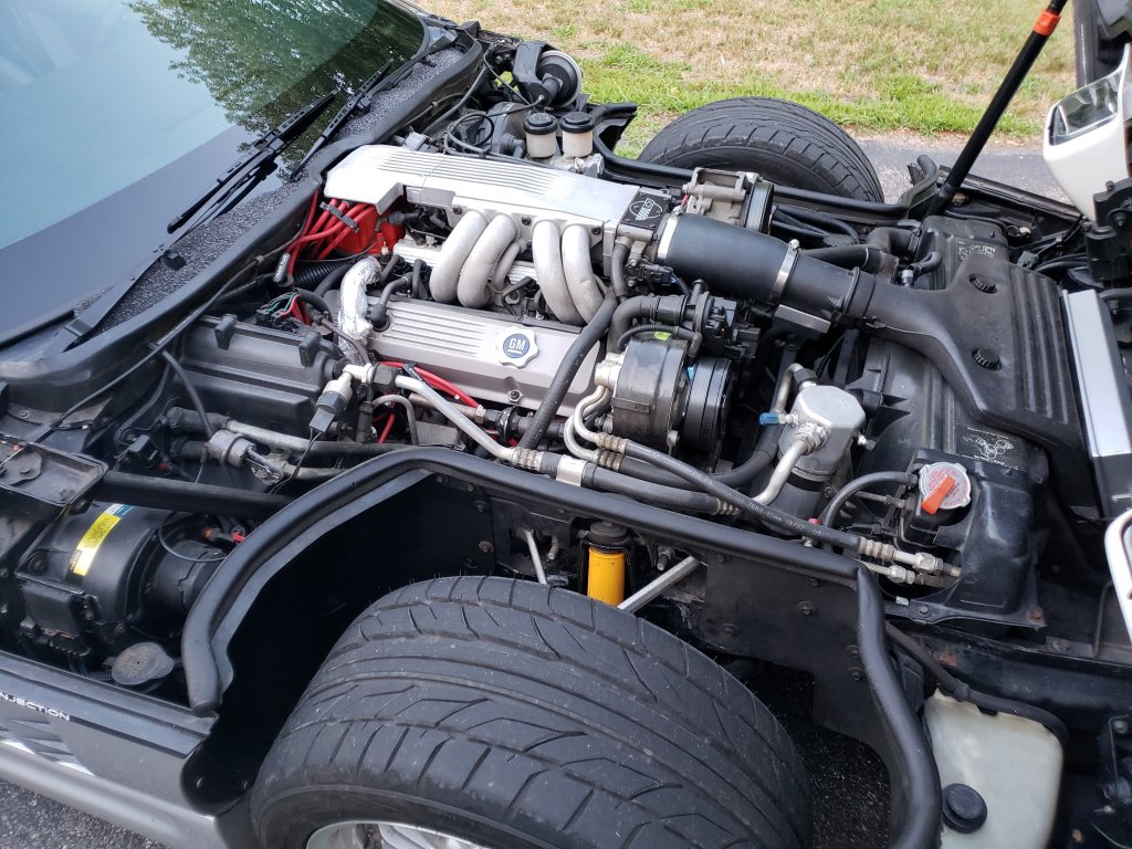
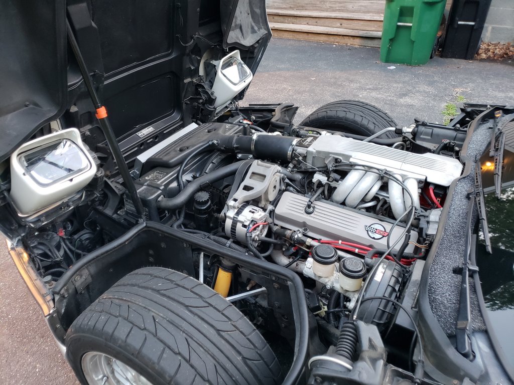
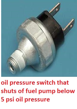
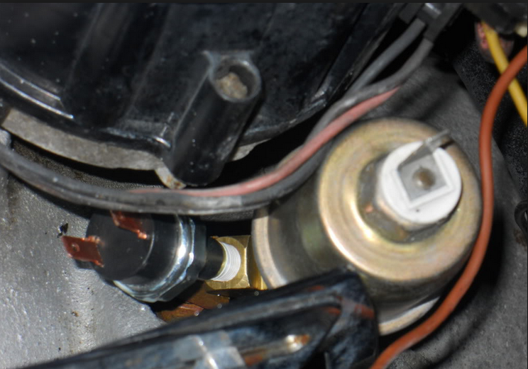
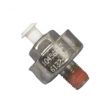
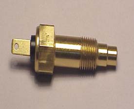
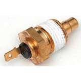
the oil system sensors are all well known potential sources for oil leaks ,and ignition problems as a defective sensor, cuts off the ignition,
READ THE LINKS
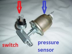
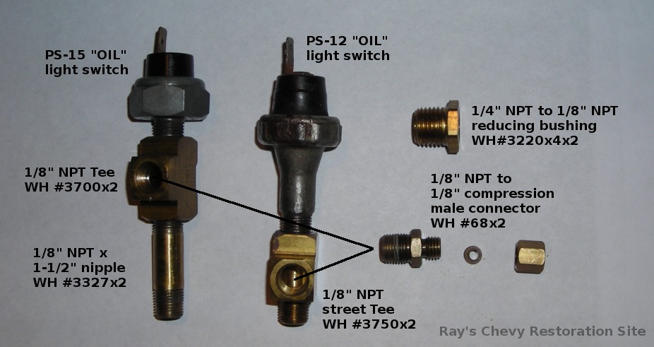
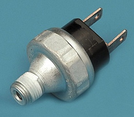
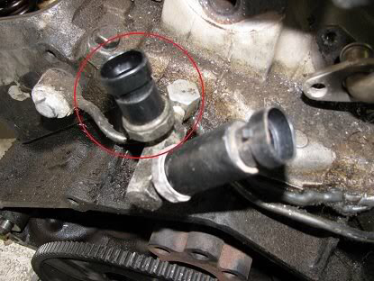
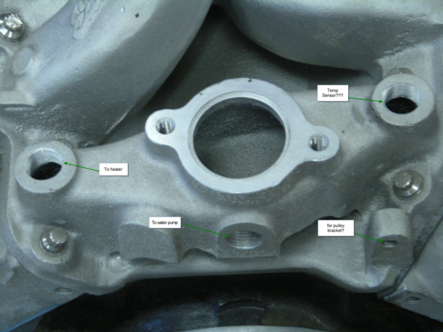
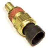
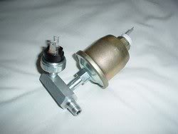
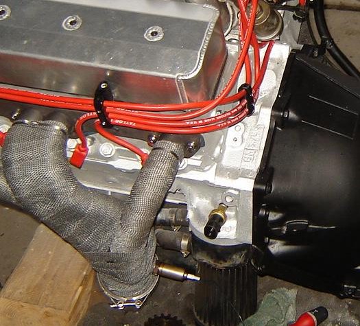
but the two blade sensor on the rear of the block, near the distributor base on the early c4 is a known , frequently defective part, and not only will it leak oil, if the switch is defective the fuel pump operation is random or not functional, it will also as it goes defective give intermittent or oil pressure readings that fluctuate.
if you start seeing oil on the rear of the block, its not always a defective rear seal , loose oil filter or loose defective rear intake manifold gasket, check the sensors near the distributor base.


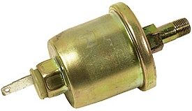
http://www.ecklers.com/corvette-oil-pressure-sender-1985-1987.html
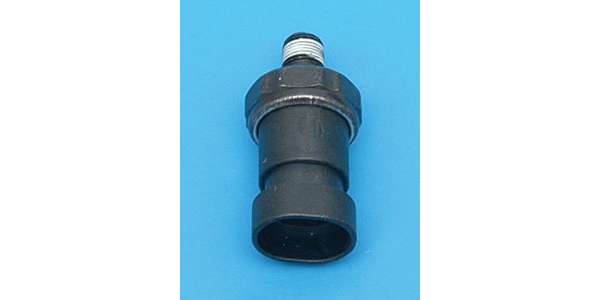
http://www.ecklers.com/corvette-fuel-pump-switch-oil-pressure-sender-1989-1996.html
Corvette Fuel Pump Switch/Oil Pressure Sender, 1989-1996
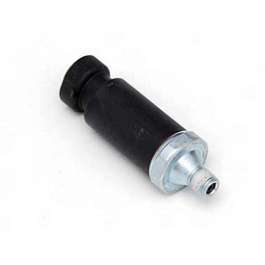
Corvette Oil Pressure Sender, 1985-1987
http://www.ecklers.com/corvette-oil-pressure-sender-1985-1987.html?crosssell=Product_Viewed
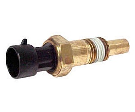
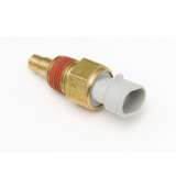
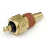
Corvette Oil Temperature Sensor, 1990-1996
http://www.ecklers.com/corvette-oil-temperature-sensor-1990-1996.html

get out your shop manual and multi meter
[/b][/color]
read thru these links
http://members.shaw.ca/agent86/Fuel Control And Delivery-8A.pdf
http://members.shaw.ca/corvette86/EngineCranksButWontRun.pdf
http://members.shaw.ca/corvette86/FuelSystemDiagnosis.pdf
http://members.shaw.ca/corvette86/No-Service Engine Soon - Light.pdf
http://members.shaw.ca/corvette86/SES Light On Steady.pdf
http://members.shaw.ca/corvette86/Non Scan Diagnostic Circuit Check.pdf
http://members.shaw.ca/corvette86/Engine to ECM Wiring Diagram 86.pdf
http://members.shaw.ca/corvette86/Component Location View 86.pdf
http://www.summitracing.com/parts/hfm-zfswf/overview/
http://static.summitracing.com/global/i ... -zfswf.pdf
http://www.summitracing.com/parts/hfm-zfswfk/overview/
http://members.shaw.ca/corvette86/FuelSystemDiagnosis.pdf
]
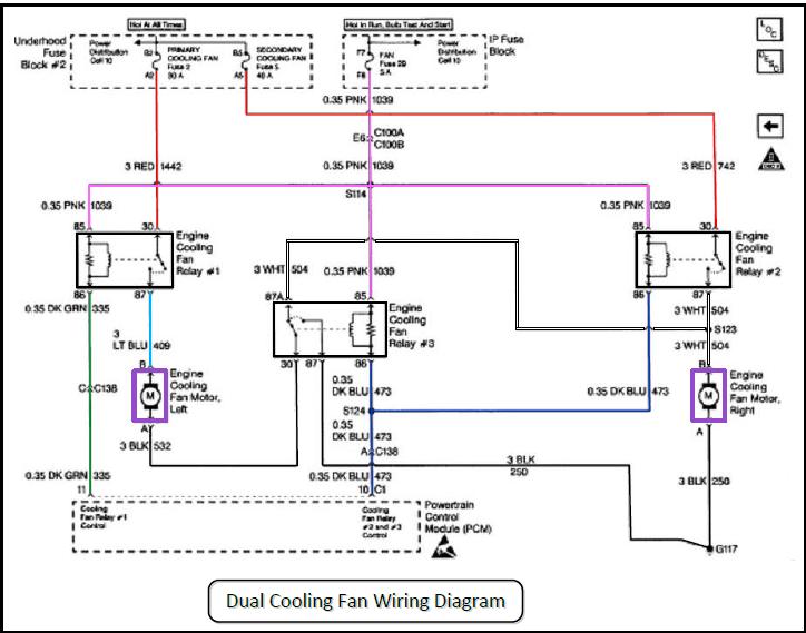
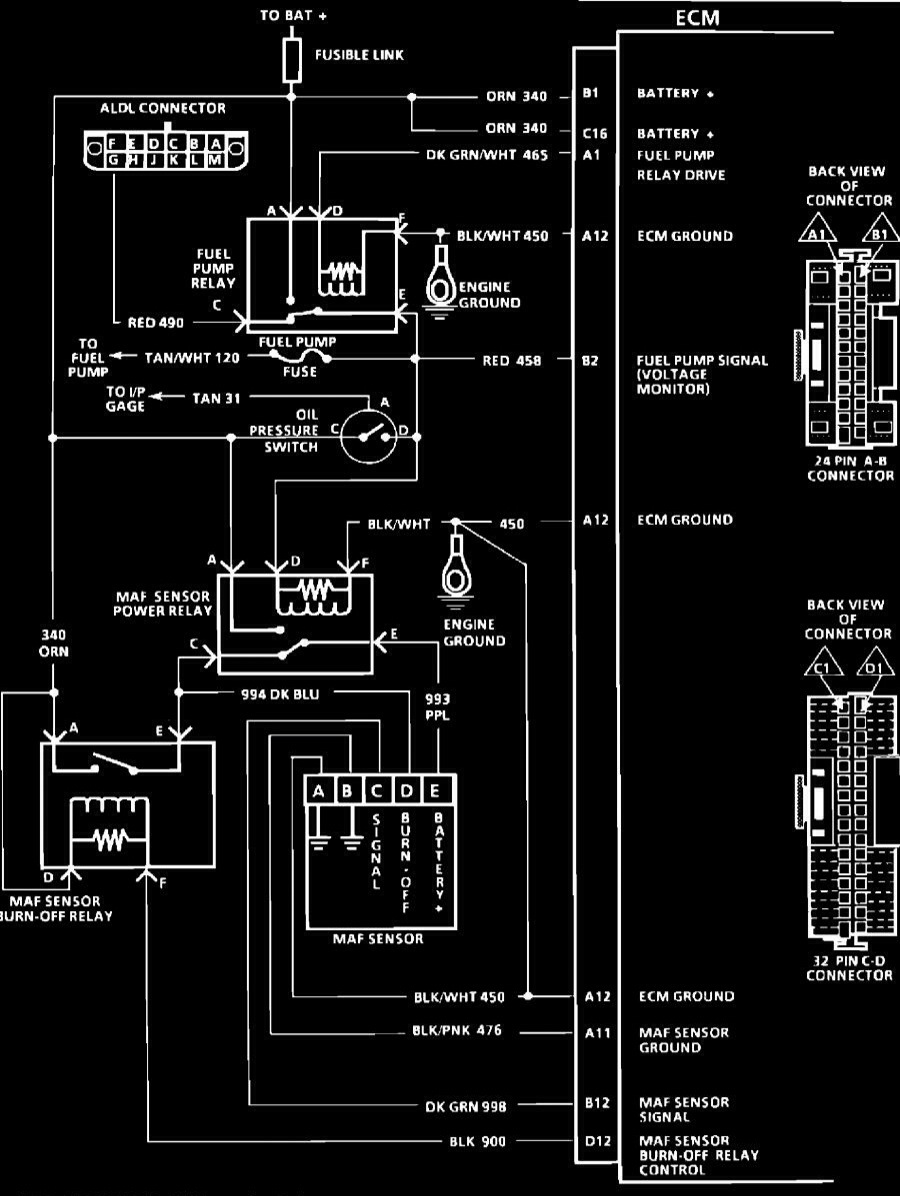
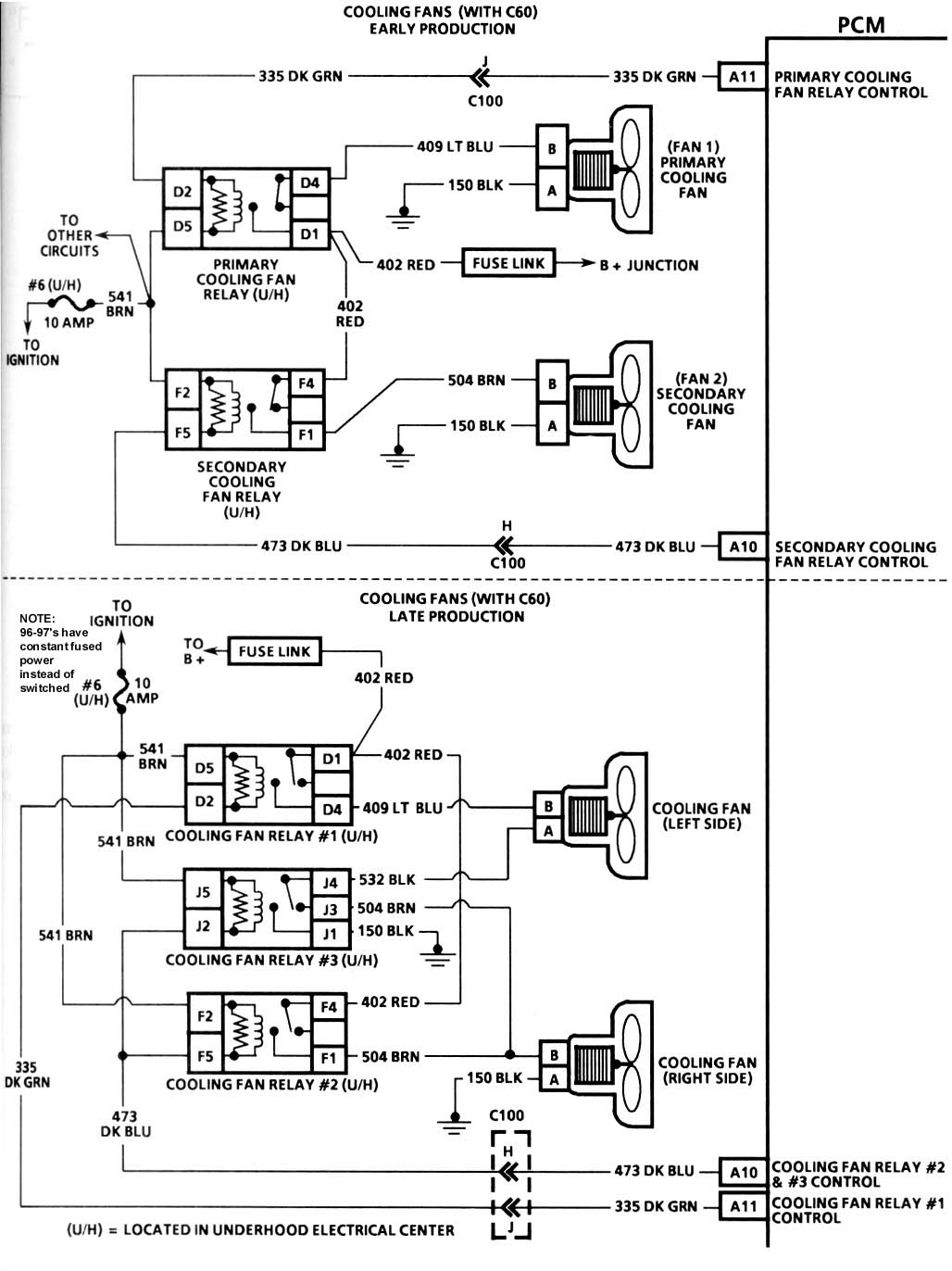
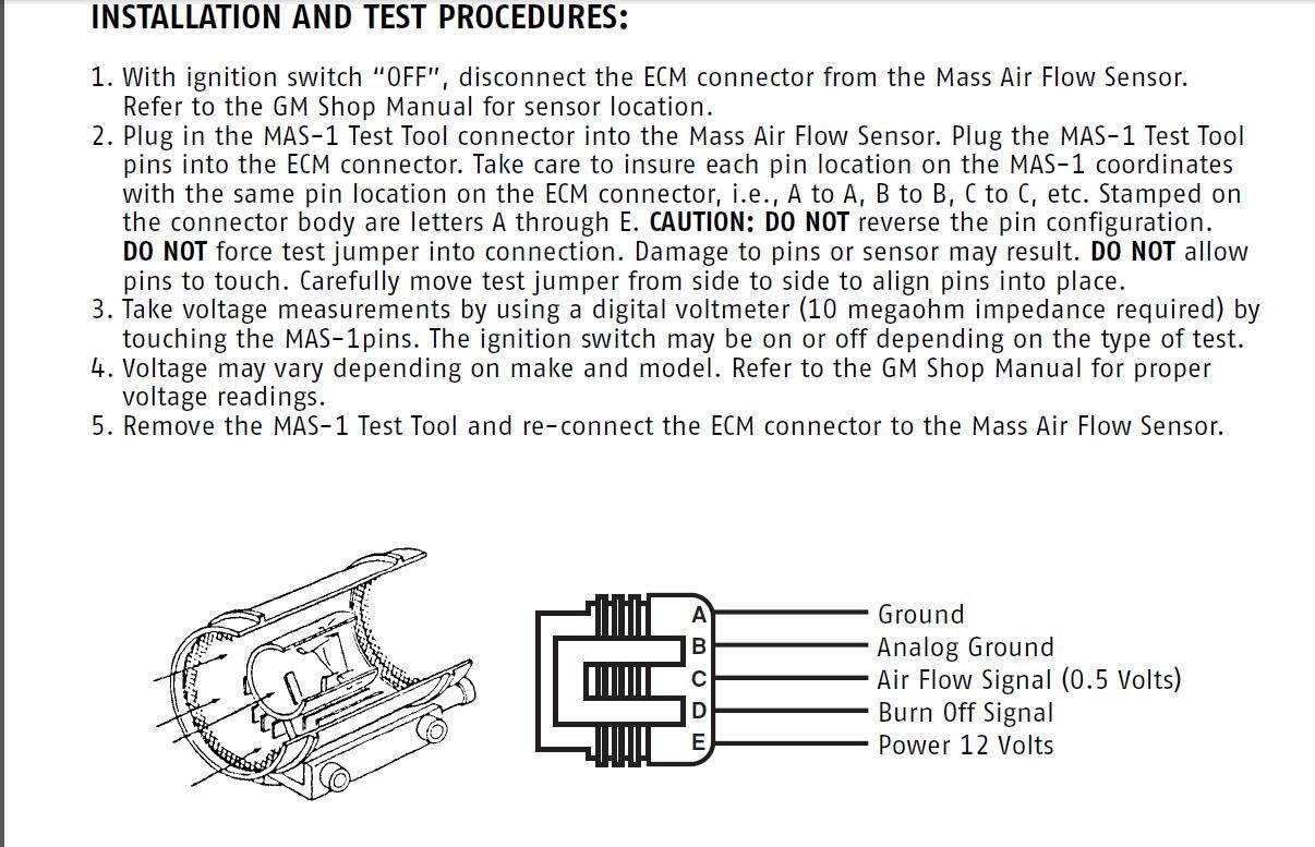
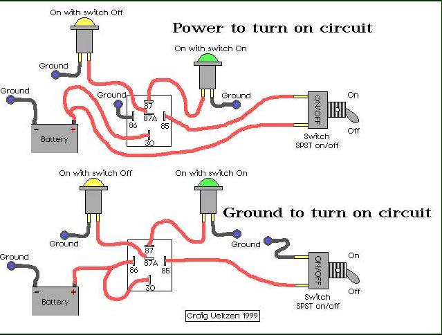
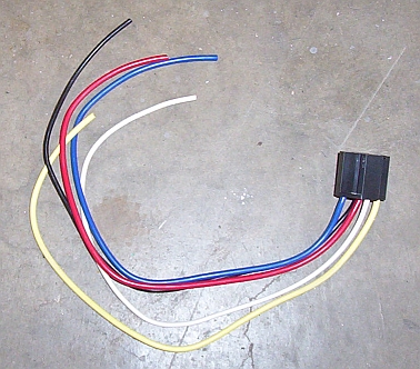
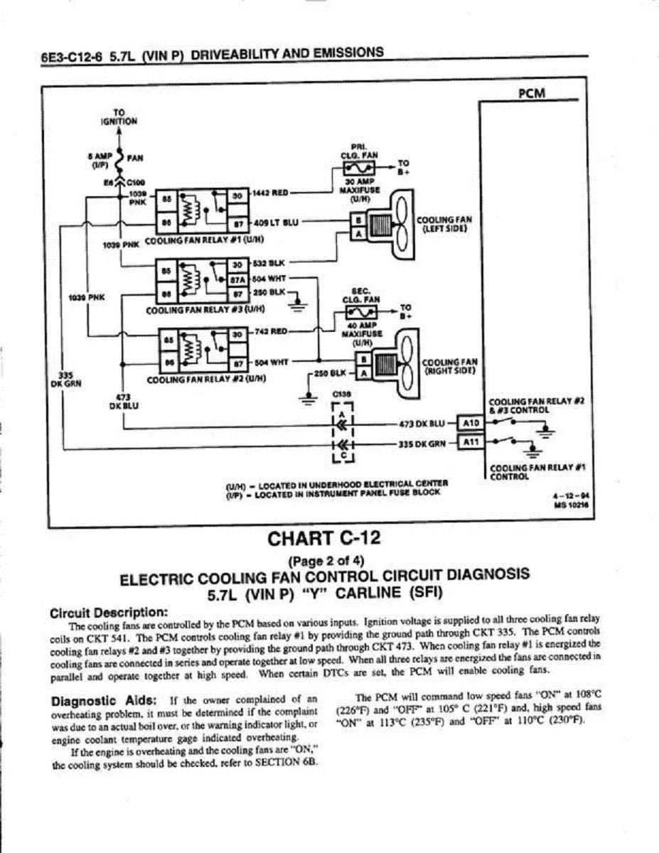
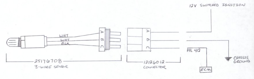
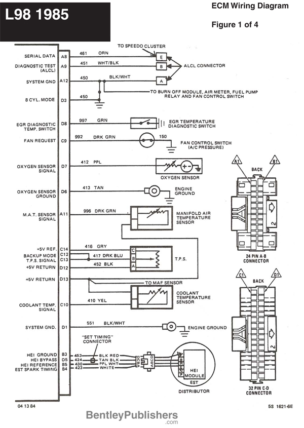
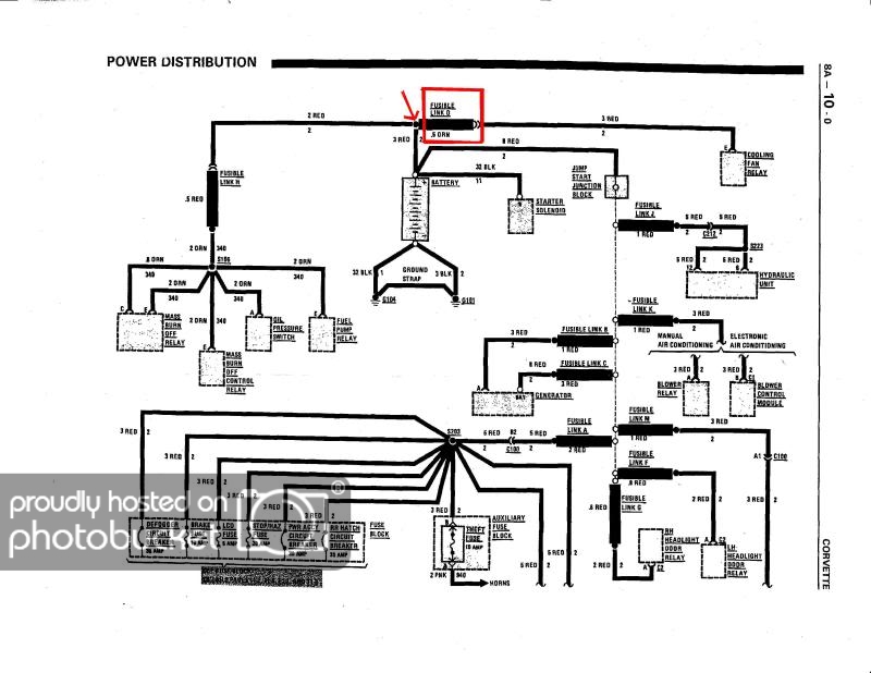
THE DIAGRAM ABOVE HAS THE CORRECT WIRE COLORS
BTW FAULTY GROUNDS, IN MANY CARS AND ESPECIALLY NEWER CORVETTES CAUSE MANY ELECTRICAL ISSUES SO IF YOU HAVE INTERMITTENT ELECTRICAL ISSUES CHECK THEM CAREFULLY
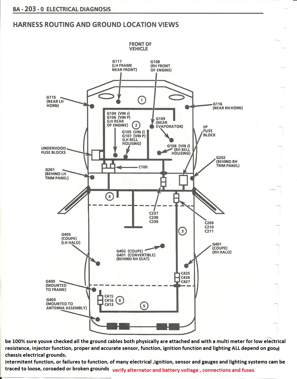
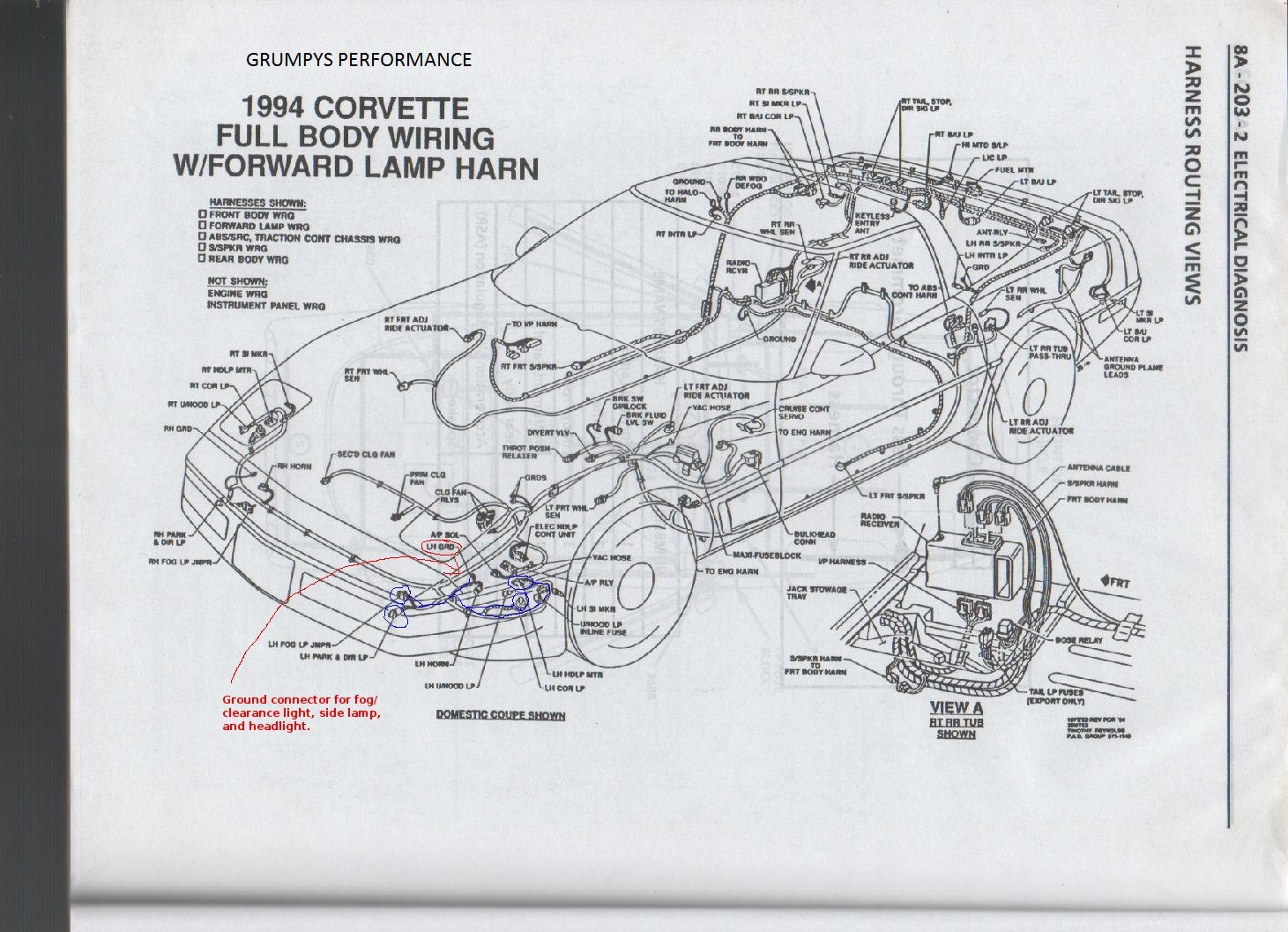
LCD dash ground is behind drivers kick panel . There are also several electrical grounds down just above the oil filter and one behind the passenger kick panel for the ECM. and a couple on the rear of the drivers side cylinder head, Grounds are a constant issue on most c4's. Hope this helps.
READ THE THREAD THRU TO THE END AND BE AWARE IT, AND ALL OTHER THREADS ARE CONSTANTLY UPDATED WITH NEW LINKS AND INFO
without testing you simply guessing
never guess, deal in verified FACTS!
guessing is a waste of time
think logically, isolate and test
LOOK FOR LOOSE OR CORRODED ELECTRICAL WIRING CONNECTORS, in THE WIRING HARNESS, and VERIFY YOUR FIRING ORDER, YEAH I KNOW YOUR SURE ITS CORRECT, CHECK IT CAREFULLY AGAIN, YOUR NOID TEST LIGHT AND MULTI- METER CAN SAVE YOU A GREAT DEAL OF PROBLEMS AND SCRATCHING YOUR HEAD IF YOU TEST BASIC ELECTRICAL CONNECTIONS< RESISTANCE AND VOLTAGE, CHECK YOUR SENSORS AND GROUNDS, A SHOP MANUALS MANDATORY, HEAT SENSORS AND IGNITION MODULES AND OIL PRESSURE SENSORS HAVE A LONG TRACK RECORD OF FAILING OR PARTIALLY AND INTERMITTENTLY NOT FUNCTIONING
IM JUST CURIOUS?
how many of you gentlemen go to a computer, print out related wiring diagrams ,get out a multi meter and a shop manual and actually read the shop manual, and step thru the indicated testing procedures? check for voltage ohms resistance, loose connections, etc. and have actually used the shop manual, multi meter and printed wiring diagrams ans instructions to isolate and solve a problem on your car?
https://www.corvettecentral.com/c4-84-96/96-shop-service-manual-cd-rom-114143?returnurl=/c4-84-96/?count=9
if you have at lease 38 psi in the fuel rail, and it holds at or near at least 38 psi for at least a couple minutes after you stop cranking the engine, the fuel pressure regulator is most likely functioning correctly, but you state the injectors are not squirting fuel and the pump keeps running while you crank the engine?
you can test the electrical connectors on the injectors with a noid test light to watch the electric pulse,at each injector location, ID verify timing injector resistance,and check for vacuum leaks while testing, and remember theres a 9th cold start injector on the 1985-88 TPI fuel rail
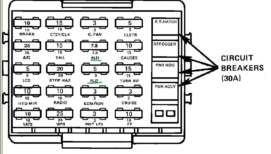
first check your shop manual for the fuse and fuse able link locations
fuses are located in several locations and fuse-able links near the battery, NOW GET A MULTI METER AND CHECK ALL THE FUSES , AND GROUNDS AND BATTERY VOLTAGE AND ELECTRICAL CONNECTIONS LIKE BATTER CABLES AND SENSOR WIRE CONNECTIONS, BECAUSE A SURPRISING NUMBER OF PROBLEMS ON OLDER CORVETTES AND MUSCLE CARS ARE RELATED TO BLOWN FUZES, LOOSE OR CORRODED CONNECTORS, AND BAD BATTERY CONNECTION CABLES OR WEAL BATTERY'S OR DEFECTIVE ALTERNATORS
HERES A FEW USEFUL, related bit of info and LINKS YOU MIGHT WANT TO LOOK THRU
and yes they should all read very closely) then you need a noid kit for a G.M. fuel injection system, these are basically little lights that light as the injector pulse hits them that you plug into the injector harness,after you remove the harness from the injectors, they plug into the harness just like an injector, if you try to start the engine and they blink on and off the pulse is reaching the injectors thus proving that the injectors get the pulse, each injector should get a pulse and you should see each noid light flash, if you don,t theres an electrical or wiring issue, that must be addressed.
injectors normal state is CLOSED they open only with a electric pulse, the duration of the pulse controls the volume of fuel flow
carefully visually inspect your cars wire harness for corrosion ,loose or broken or shorting connectors or wiring, obviously getting the wrong electrical pulse, a grounded or shorted connector will cause problems.
a NOID light can be used to test, the pulse is intermittent if plugged into the cars wire harness and its more likely the injector needs cleaning
http://www.harborfreight.com/11-piece-n ... 97959.html
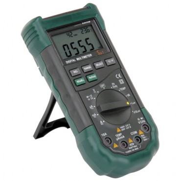
set up a multi meter like this and pull fuses one at a time to locate shorted circuits
replacement injector pig tails are available at rock auto for less than $5 each
read these links and
related sub links
pull trouble codes
http://garage.grumpysperformance.co...oven-facts-if-your-in-doubt.13051/#post-84695
http://forum.grumpysperformance.com/viewtopic.php?f=32&t=1401&p=8895&hilit=start+sequence#p8895
http://garage.grumpysperformance.com/index.php?threads/c4-c5-corvette-trouble-codes.2697/
http://garage.grumpysperformance.com/index.php?threads/lots-of-wiring-info-diagrams.317/#post-83877
http://garage.grumpysperformance.com/index.php?threads/adjusting-your-tps-and-iac.168/
http://garage.grumpysperformance.com/index.php?threads/multi-meters.3110/#post-71867
http://garage.grumpysperformance.com/index.php?threads/1990-corvette-no-spark.13857/#post-70888
http://garage.grumpysperformance.com/index.php?threads/diagnoseing-tpi-lt1-problems.1241/
reading links and sub links can help
replacement connectors and pigtails are available
http://garage.grumpysperformance.com/index.php?threads/lots-of-wiring-info-diagrams.317/#post-83877
http://garage.grumpysperformance.co...-auto-elecrtrical-connectors.3105/#post-68805
http://garage.grumpysperformance.co...cting-a-distributor-for-your-application.855/
http://garage.grumpysperformance.co...-idles-and-sometimes-stalls.10688/#post-46397
viewtopic.php?f=36&t=3105&p=8272&hilit=connectors+pigtails#p8272
viewtopic.php?f=32&t=168&p=41767&hilit=connectors+pigtails#p41767
http://garage.grumpysperformance.co...lay-switch-locations-and-info.728/#post-17654
reading thru a few links might be helpful
step #1
always ISOLATE AND VERIFY, TEST EVERYTHING ASSUME NOTHING!
IF YOU skip the links and you'll miss a good deal of useful info
ANY TIME YOU SUSPECT FUEL INJECTOR OR FUEL SYSTEM RELATED ISSUES ,A REASONABLE START POINT IS TO USE A GOOD QUALITY FUEL INJECTION CLEANER ADDITIVE IN THE FUEL TANK AND SWAP TO A NEW FUEL FILTER
http://www.bgprod.com/catalog/gasoline- ... m-cleaner/
http://www.bgprod.com/catalog/gasoline- ... m-cleaner/
AND YES AMAZINGLY, ACTUALLY READING THRU THE POSTED LINKS AND SUB LINKS might help
http://www.chevythunder.com/fuel%20inje ... pg%20B.htm
http://www.mainstreamtopics.com/forums/ ... iagnostic/
http://www.mamotorworks.com/corvette-c4 ... -6128.html
http://garage.grumpysperformance.co...start-right-back-up-and-run.10739/#post-46893
Intake Air Temp sensor. It is located on the bottom of the inlet plenum a few inches ahead of the distributor. It is like right next to the fuel pressure regulator., it can effect fuel flow rates
If your experiencing intermittent electrical issues you will obviously need to get out the shop manual for your year corvette, a multi meter and do some isolate and testing, but be aware that loose or corroded connections , will be hard to isolate, as they seldom present a consistent, solid open or dead short in the wire,theres several electrical connector plugs that connect thru the firewall near the battery location that are subject to corrosion issues and frame grounds that might be suspect, obviously theres sensors that can be defective.
links with lots of sub-links that should be useful, most guys ,faced with isolating an electrical issue, seem to get over whelmed, but if you get out the schematics, use a multi meter and some logic in tracing the circuits, and start pulling fuses and measuring resistance and voltage, take the time to read the manual ,pull trouble codes,and if required get a scan tool or a data logging program for your lap top computer, and using the shop manual, you can generally isolate the cause
http://forum.grumpysperformance.com/viewtopic.php?f=80&t=728&p=9217&hilit=+sensors+location#p9217
http://forum.grumpysperformance.com/viewtopic.php?f=32&t=1401&p=39419&hilit=+sensors+location#p39419
http://forum.grumpysperformance.com/viewtopic.php?f=32&t=2697&p=29270&hilit=+sensors+location#p29270
viewtopic.php?f=50&t=8136&p=28980&hilit=scan+tool#p28980
viewtopic.php?f=27&t=3096&p=18612&hilit=scan+software#p18612
viewtopic.php?f=44&t=758&p=1087&hilit=opti+crap#p1087
http://forum.grumpysperformance.com/viewtopic.php?f=32&t=1401
http://forum.grumpysperformance.com/viewtopic.php?f=32&t=168
viewtopic.php?f=2&t=3074&p=8144#p8144
viewtopic.php?f=36&t=3222&p=8575&hilit=test+alternator#p8575
viewtopic.php?f=70&t=3504&p=9220#p9220
viewtopic.php?f=36&t=8493&p=29779#p29779
viewtopic.php?f=44&t=3401&p=8972&hilit=test+alternator#p8972
viewtopic.php?f=55&t=1241&p=3037&hilit=test+alternator+coil+test#p3037
viewtopic.php?f=50&t=609&p=810&hilit=test+alternator+coil+test#p810
http://forum.grumpysperformance.com/viewtopic.php?f=32&t=596
http://scehovic.angelfire.com/C4starts.html
http://forum.grumpysperformance.com/viewtopic.php?f=70&t=4683
http://shbox.com/1/component_location_views.html
http://www.smogtips.com/trouble-codes.cfm
http://www.aa1car.com/library/us796obd.htm
viewtopic.php?f=57&t=2538&p=6984#p6984
viewtopic.php?f=32&t=2697&p=6985#p6985
viewtopic.php?f=36&t=768&p=2394&hilit=+manual#p2394
viewtopic.php?f=36&t=520&p=645&hilit=vats+resistor#p645
don,t get over whelmed,
simply break the problem down to testing each basic sub system,
test each related sensor and electrical component and electrical sensor and connection.
some reading on the threads posted below, a bit of logic and deductive reasoning, and a multi meter and a shop manual will go a long way toward finding and fixing the problem.
Measured Value
Engine Coolant Temperature Sensor. 185 Ohms @ 210F, 3400 Ohms @ 68F, 7,500 Ohms @ 39 F.
Engine Oil Temperature Sensor. 185 Ohms @ 210 F, 3400 Ohms @ 68 F, 7,500 Ohms @39 F.
Oil Pressure Sender/Switch. 1 Ohms @ 0 PSI, 43 Ohms @ 30 PSI, 86 Ohms @ 60 PSI.
Fuel Quantity Sender. 0 Ohms @ Empty, 45 Ohms @ 1/2 Full, 90 Ohms @ Full.
MAT (Manifold Absolute Temperature Sensor). 185 Ohms @ 210 F, 3400 Ohms @ 70 F, 15,000 Ohms @ 40 F.
Outside Temperature Sensor. 4400 Ohms @ 60 F, 2200 Ohms @ 85 F.
In Car Temp Temperature Sensor. 4400 Ohms @ 60 F, 2200 Ohms @ 85 F.
MAF (Mass Air Flow) Sensor. .4 Volts @ idle, 5 Volts @ Full Throttle.
Oxygen (O2) Sensor. .1 Volt Lean Mixture, .9 Volt Rich Mixture.
TPS (Throttle Position Sensor). .54 Volts Idle, ~ 5 Volts Full Throttle.
Sensor Locations
Sensor
Location
Engine Coolant Temperature Sensor. Front of engine, below Throttle Body.
Engine Oil Temperature Sensor. Left rear of engine, just above the oil filter.
Oil Pressure Sender/Switch. Top, left hand rear of engine.
Fuel Quantity Sender. Top of fuel tank, beneath filler pipe escutcheon panel.
MAT (Manifold Absolute Temperature Sensor). Underside of manifold air plenum at rear.
Outside Temperature Sensor. Right side of engine, top right corner of radiator.
In Car Temp Temperature Sensor. Coupe: above left seat near interior courtesy light, Convertible: center of cargo compartment lid.
MAF (Mass Air Flow) Sensor. Front of engine ahead of throttle body.
Oxygen (O2) Sensor. Left side of engine, in exhaust pipe.
TPS (Throttle Position Sensor). Right side of throttle body at the front.
sensor locations
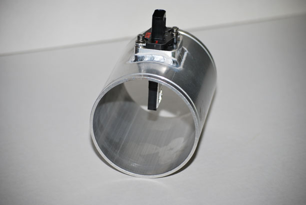
- Mass Air Flow (MAF), mounts in intake ducting between air filter and throttle body.
- Throttle Position Sensor (TPS), mounts on right side of throttle body.
- Idle Air Control valve (IAC), mounts in small manifold on bottom of throttle body.
- MAF power relay, in relay center on firewall beside master cylinder.
- MAF burn off relay, in relay center on firewall beside master cylinder.
- Manifold Air Temperature sensor (MAT), mounts in bottom of plenum near the back
- Coolant Temperature Sensor (CTS), mounts on front right of intake manifold base, below IAC valve
- Cold start switch, front right of intake manifold base, below CTS
- Exhaust Gas Recirculation valve(EGR), on top of intake manifold base, centered under plenum
- EGR solenoid, on top of intake manifold, rear, between distributor and valve cover.
- EGR diagnostic switch, on base of EGR valve.
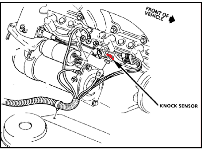
- Electronic Spark Control (ESC)knock sensor, bottom right of engine block, in front of starter just above oil pan rail, in the coolant drain boss.
- ESC module, in relay center on firewall beside master cylinder
- Electronic Spark Timing (EST) module, on distributor.
- Oxygen (O2) sensor, in left exhaust manifold.
- Air Injection Reactor (AIR) convertor divert solenoid and port solenoid, both together at front of right valve cover.
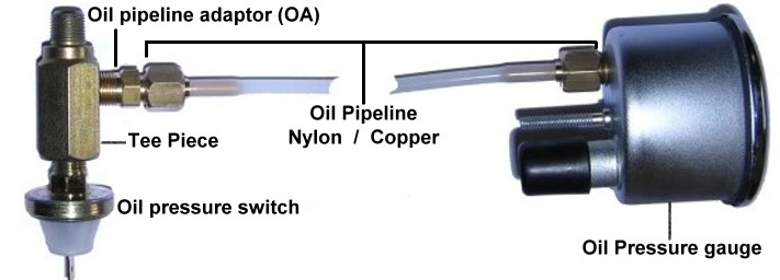
- Oil pressure switch, on Y fitting with oil pressure gauge sender mounted in the oil pressure boss on the top left rear of the engine block behind intake manifold base. (applies power to fuel pump if fuel pump relay or relay circuit fails).
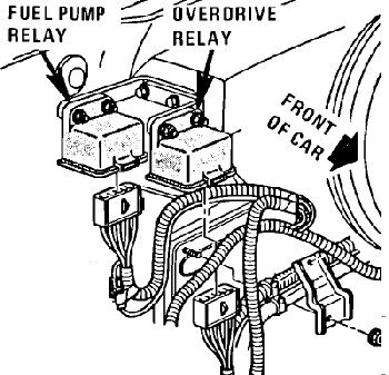
- Fuel pump relay, in relay center on firewall beside master cylinder.
- Fuel vaper canister (charcoal can) solenoid, on top of charcoal can in front left corner of engine bay.
- Air Conditioner (AC) pressure switch, in boss on AC high pressure side aluminum tube beside right strut tower.
- vehicle speed sensor, back of speedometer.
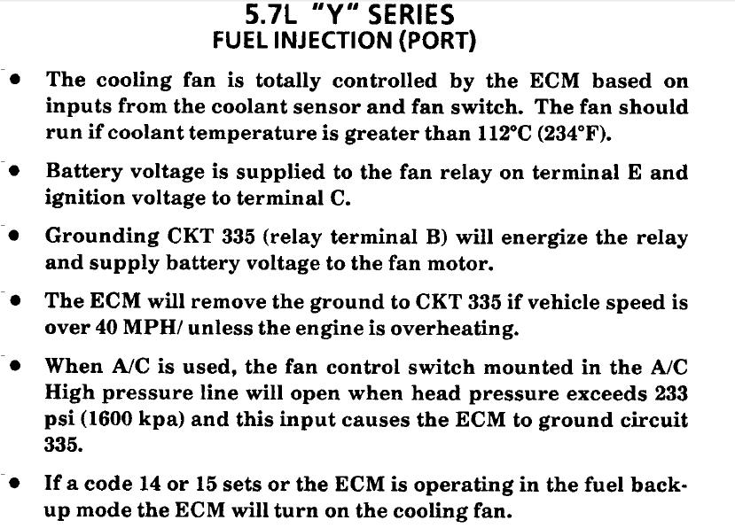
- Cooling fan relay, on core support beside battery.
knowing whats going on and WHY can help
http://www.corvettefever.com/techarticl ... index.html
http://members.shaw.ca/corvette86/Component Location View 86.pdf
http://members.shaw.ca/corvette86/FuelSystemDiagnosis.pdf
http://www.summitracing.com/parts/HYP-4026/
http://www.summitracing.com/parts/HDA-3653/
Sensor
Location
Engine Coolant Temperature Sensor. Front of engine, below Throttle Body.
Engine Oil Temperature Sensor. Left rear of engine, just above the oil filter.
viewtopic.php?f=54&t=1396&p=3221&hilit=+switch#p3221
Oil Pressure Sender/Switch. Top, left hand rear of engine.
Fuel Quantity Sender. Top of fuel tank, beneath filler pipe escutcheon panel.
MAT (Manifold Absolute Temperature Sensor). Underside of manifold air plenum at rear.
Outside Temperature Sensor. Right side of engine, top right corner of radiator.
In Car Temp Temperature Sensor. Coupe: above left seat near interior courtesy light, Convertible: center of cargo compartment lid.
MAF (Mass Air Flow) Sensor. Front of engine ahead of throttle body.
http://tpiparts.net/85_89_maf_sensors/
Oxygen (O2) Sensor. Left side of engine, in exhaust pipe.(some years have two ,one on both sides)
TPS (Throttle Position Sensor). Right side of throttle body at the front.
Sensor Outputs:
Sensor
Measured Value
Engine Coolant Temperature Sensor. 185 Ohms @ 210F, 3400 Ohms @ 68F, 7,500 Ohms @ 39 F.
Engine Oil Temperature Sensor. 185 Ohms @ 210 F, 3400 Ohms @ 68 F, 7,500 Ohms @39 F.
Oil Pressure Sender/Switch. 1 Ohms @ 0 PSI, 43 Ohms @ 30 PSI, 86 Ohms @ 60 PSI.
Fuel Quantity Sender. 0 Ohms @ Empty, 45 Ohms @ 1/2 Full, 90 Ohms @ Full.
MAT (Manifold Absolute Temperature Sensor). 185 Ohms @ 210 F, 3400 Ohms @ 70 F, 15,000 Ohms @ 40 F.
Outside Temperature Sensor. 4400 Ohms @ 60 F, 2200 Ohms @ 85 F.
In Car Temp Temperature Sensor. 4400 Ohms @ 60 F, 2200 Ohms @ 85 F.
MAF (Mass Air Flow) Sensor. .4 Volts @ idle, 5 Volts @ Full Throttle.
Oxygen (O2) Sensor. .1 Volt Lean Mixture, .9 Volt Rich Mixture.
TPS (Throttle Position Sensor). .54 Volts Idle, ~ 5 Volts Full Throttle.
IAC and TPS Adjustment
http://www.thirdgen.org/tpimod2
TPI Injector Swap
http://www.thirdgen.org/injectorswap
Throttle Body Coolant Bypass
http://www.thirdgen.org/coolantbypass
http://www.jcwhitney.com/autoparts/Sear ... p=ZX503796
http://www.summitracing.com/parts/SUN-CP9001
http://www.etoolcart.com/autoxray-scann ... x6000.aspx
viewtopic.php?f=32&t=304
ID also suggest buying a diagnostic tool, with real time data logging to a lap top computer, and your shop manual, it helps isolate problems, ignition spark should be bright blue and impressive, if its, weak,narrow, yellow or red theres a problem so research the cause, verify the coil and voltage
the oil system sensors are all well known potential sources for oil leaks ,and ignition problems as a defective sensor, cuts off the ignition,
READ THE LINKS
but the two blade sensor on the rear of the block, near the distributor base on the early c4 is a known , frequently defective part, and not only will it leak oil, if the switch is defective the fuel pump operation is random or not functional, it will also as it goes defective give intermittent or oil pressure readings that fluctuate.
if you start seeing oil on the rear of the block, its not always a defective rear seal , loose oil filter or loose defective rear intake manifold gasket, check the sensors near the distributor base.
http://www.ecklers.com/corvette-oil-pressure-sender-1985-1987.html
http://www.ecklers.com/corvette-fuel-pump-switch-oil-pressure-sender-1989-1996.html
Corvette Fuel Pump Switch/Oil Pressure Sender, 1989-1996
Corvette Oil Pressure Sender, 1985-1987
http://www.ecklers.com/corvette-oil-pressure-sender-1985-1987.html?crosssell=Product_Viewed
Corvette Oil Temperature Sensor, 1990-1996
http://www.ecklers.com/corvette-oil-temperature-sensor-1990-1996.html
get out your shop manual and multi meter
[/b][/color]
read thru these links
http://members.shaw.ca/agent86/Fuel Control And Delivery-8A.pdf
http://members.shaw.ca/corvette86/EngineCranksButWontRun.pdf
http://members.shaw.ca/corvette86/FuelSystemDiagnosis.pdf
http://members.shaw.ca/corvette86/No-Service Engine Soon - Light.pdf
http://members.shaw.ca/corvette86/SES Light On Steady.pdf
http://members.shaw.ca/corvette86/Non Scan Diagnostic Circuit Check.pdf
http://members.shaw.ca/corvette86/Engine to ECM Wiring Diagram 86.pdf
http://members.shaw.ca/corvette86/Component Location View 86.pdf
http://www.summitracing.com/parts/hfm-zfswf/overview/
http://static.summitracing.com/global/i ... -zfswf.pdf
http://www.summitracing.com/parts/hfm-zfswfk/overview/
http://members.shaw.ca/corvette86/FuelSystemDiagnosis.pdf
]
THE DIAGRAM ABOVE HAS THE CORRECT WIRE COLORS
BTW FAULTY GROUNDS, IN MANY CARS AND ESPECIALLY NEWER CORVETTES CAUSE MANY ELECTRICAL ISSUES SO IF YOU HAVE INTERMITTENT ELECTRICAL ISSUES CHECK THEM CAREFULLY
LCD dash ground is behind drivers kick panel . There are also several electrical grounds down just above the oil filter and one behind the passenger kick panel for the ECM. and a couple on the rear of the drivers side cylinder head, Grounds are a constant issue on most c4's. Hope this helps.
Last edited by a moderator: