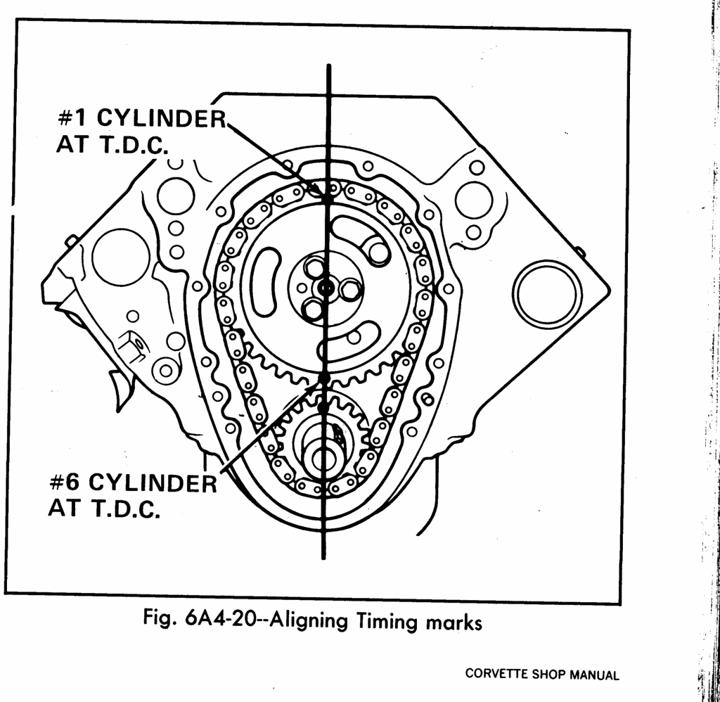
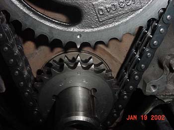
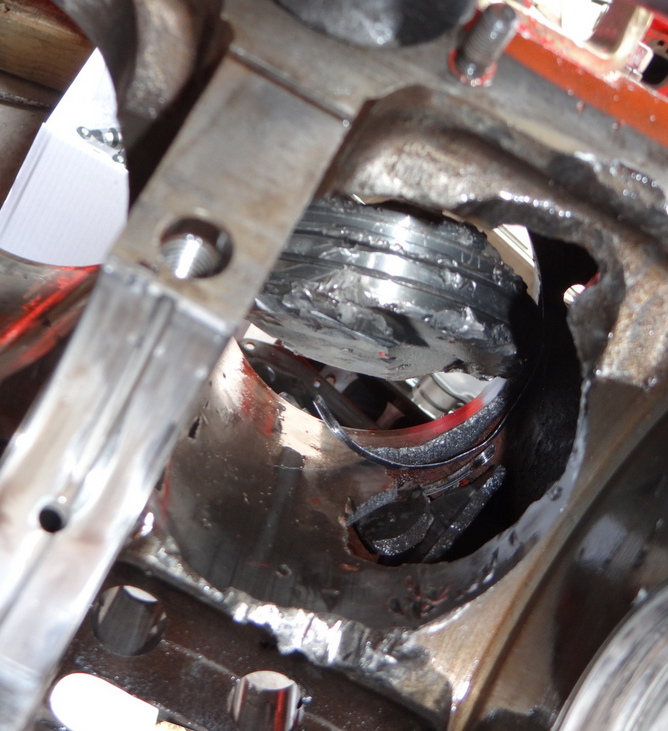
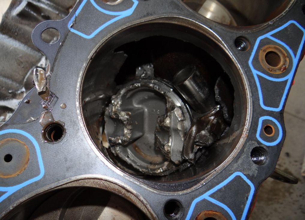
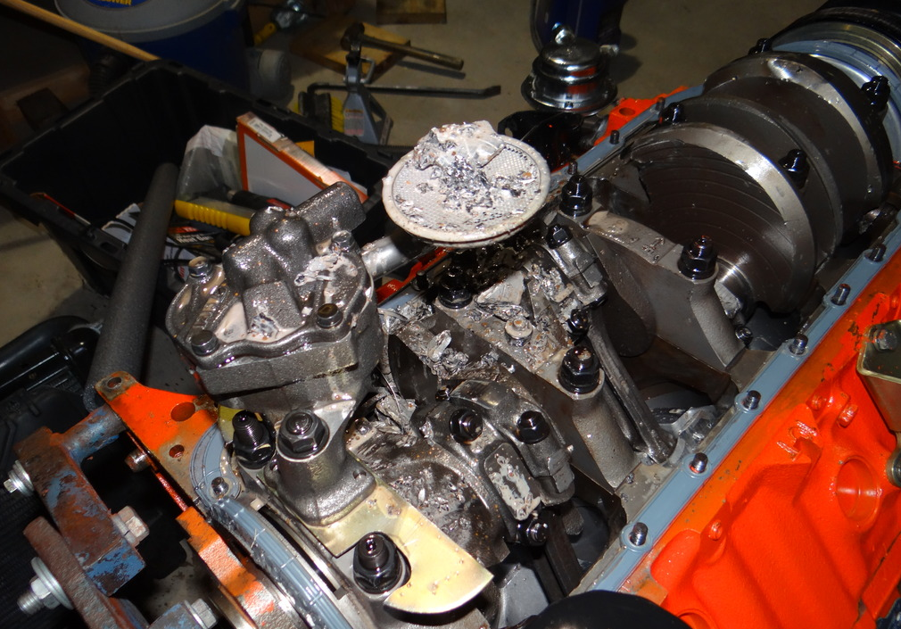
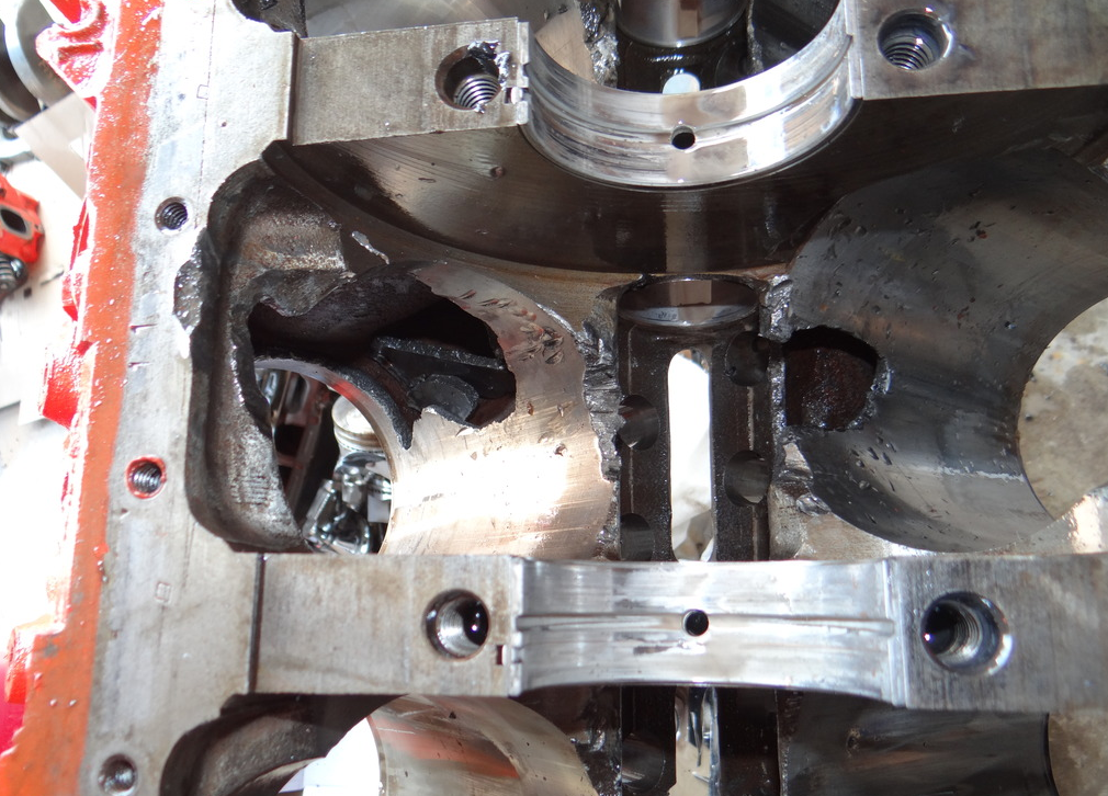
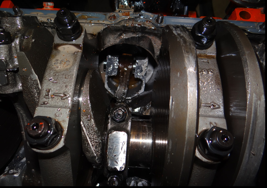
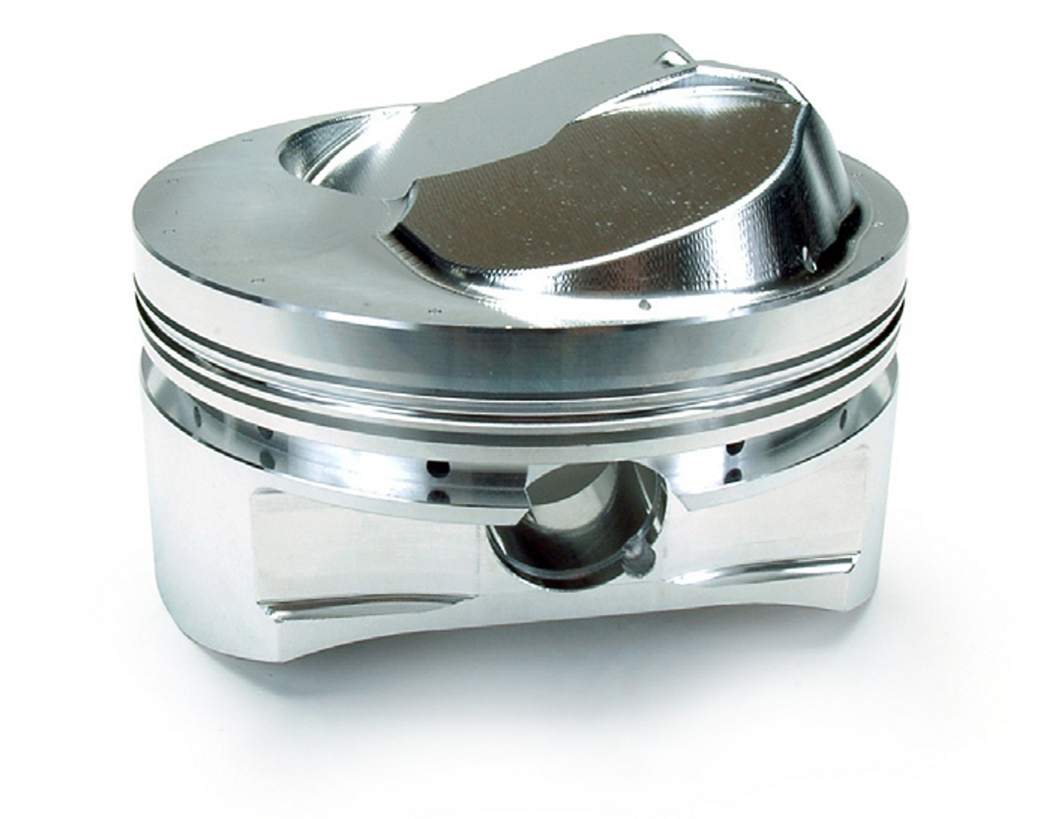
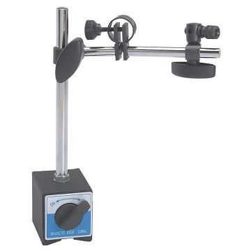
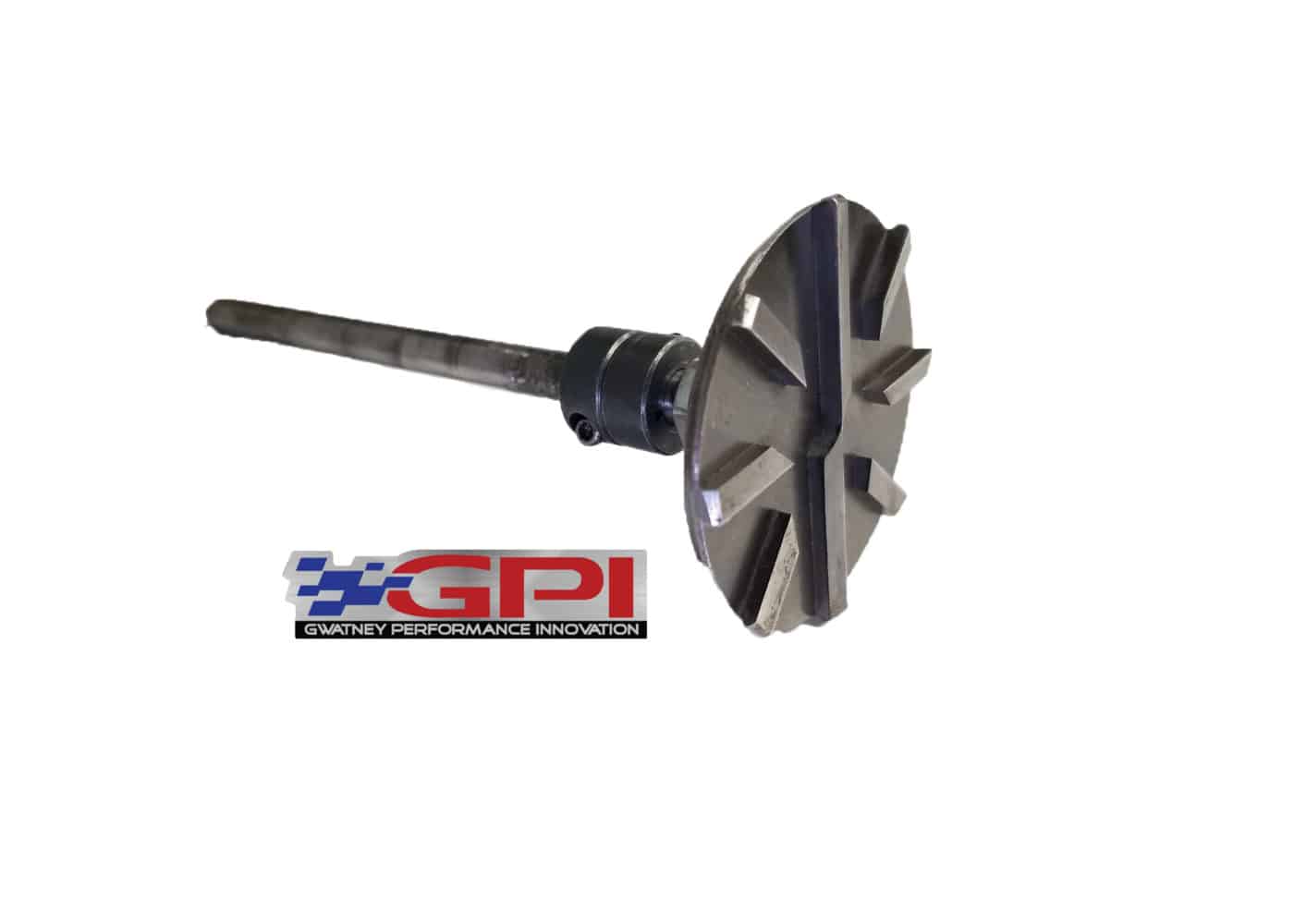
this is an old post I got asked to repost, naturally the first step is to install and correctly degree in your cam,

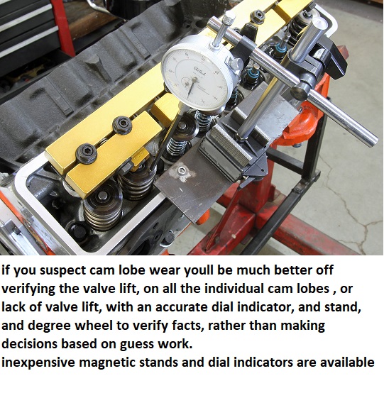
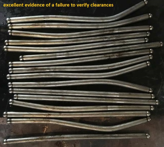
if you have a minimum of .120 on both the intake and exhaust valve on that #1 and #2 cylinder (one on each bank) I think youll be ok, measuring just that cylinder , if either the intake or exhaust valve has less than .100 ID measure all the cylinders just to be sure!
don,t forget to verify the valve edge to valve pocket clearance along with the valve face too piston deck clearances
READ THESE THREADS
http://garage.grumpysperformance.co...op-dead-center-1-for-timing-ignition-cam.966/
http://garage.grumpysperformance.co...ring-installation-questions.12833/#post-66460
http://garage.grumpysperformance.co...-pushrods-and-check-info-you-might-need.5931/
http://garage.grumpysperformance.com/index.php?threads/valve-train-clearances-and-problems.528/
http://garage.grumpysperformance.co...ectly-and-get-it-to-last-cam-install-info.90/
http://garage.grumpysperformance.com/index.php?threads/how-to-read-a-cam-spec-card.1477/
http://garage.grumpysperformance.co...ve-spring-bind-height-060-safety-margin.4957/
http://garage.grumpysperformance.com/index.php?threads/special-lifter-for-checking-cam-timing.3745/
http://garage.grumpysperformance.com/index.php?threads/valve-train-clearances-and-problems.528/
http://garage.grumpysperformance.co...e-springs-and-setting-up-the-valve-train.181/
http://garage.grumpysperformance.com/index.php?threads/can-you-plan-for-quench.11298/
http://garage.grumpysperformance.com/index.php?threads/head-gasket-related.1859/#post-50617
http://garage.grumpysperformance.com/index.php?threads/quench-or.10951/
http://garage.grumpysperformance.co...r-piston-dome-or-port-volume.2077/#post-44568
http://garage.grumpysperformance.co...needs-clean-up-equalization.12474/#post-62647
http://garage.grumpysperformance.co...ng-combustion-chambers.2630/page-2#post-55199
DON"T FORGET TO VERIFY SPRING BIND CLEARANCE AND PISTON TO VALVE CLEARANCE ETC>

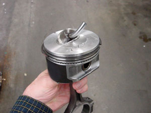
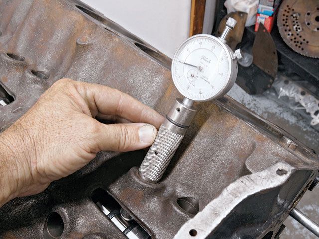
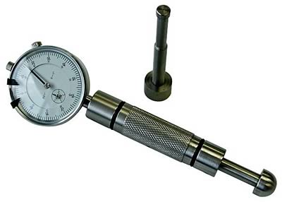
be sure you, measure EACH bore and EACH piston,
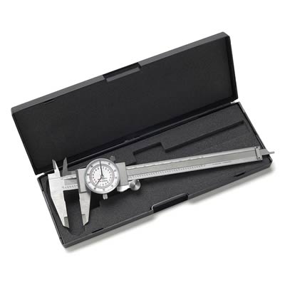
(CORRECTLY with the proper tools in the way the tool and piston manufacturers suggested)
and number them on an engine build sheet indicating the bore and piston diam.
from large to smallest on each and install them on each cylinder to get the most consistent piston to bore clearance's
yes the difference may only be a few ten thousands if the bores are machined correctly, but you'll get the best results , most consistent lubrication, best durability and less heat build up that might result in detonation issues that way. its the little things that add up to making a good durable engine assembly,
BTW check rod orientation, so the beveled sides don't fact the adjacent rods, and check the bearing clearances with plasti guage
every part you choose is a compromise , and may require changes,
that cost you in time, money or performance to some degree,
and almost every part will require a bit of fitting or clearance work,
or adjustment to fit and function to get the best results
if it drops out of the package and bolts together as it drops out of the package,
its almost certain its not functional to nearly its full potential
your job is to think things through carefully and make sure parts fit and function to their full potential,
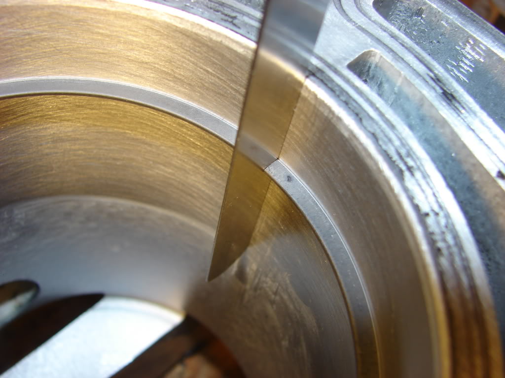
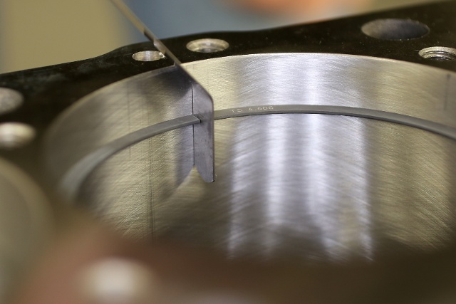
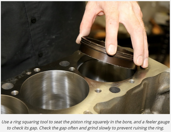
little things like checking piston ring end gap, verifying bearing clearances, and ccing the heads and checking piston to valve clearance, degreeing in the cam and verifying the valve train geometry, polishing combustion chambers, getting a decent 3 angle valve job,verifying the piston to bore clearance, MATTER's
READ THIS THREAD AND RELATED LINKED INFO
http://garage.grumpysperformance.co...rdering-correct-custom-length-pushrods.14241/
this is a common warning posted , on the subject of checking piston to valve clearance, this is from AFR website
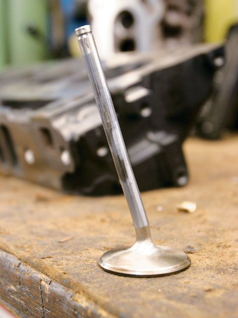
if the end user builds an engine without properly verifying he has enough piston to valve clearance (depth and radial clearance both checked). We recommend a minimum depth of .080 on the intake valve and .100 on the exhaust with a radial clearance of .200 minimum around the perimeter of each valve. Clay is recommended to visually verify both depth as well as radial clearance. Just checking depth is not enough...the position of the valve pocket must also be addressed.
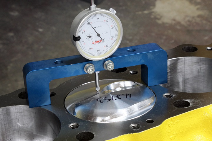
it should be rather obvious that youll need to know the exact distance the piston deck sits at TDC ,above or below the block deck surface and the valve notch recess or pop-up dome volume of the piston to do accurate quench or compression calculations
heres a few links with that info.
like always reading thru all the links gives you much more complete info...
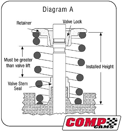
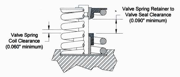
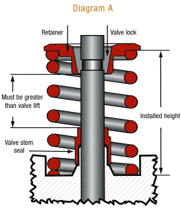
you need .090 clearance between the retainer to valve seal and a TOTAL of .060 clearance MINIMUM on the valve spring coils from spring bind, or solid stacking the spring coils

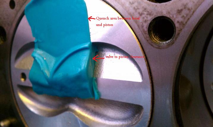
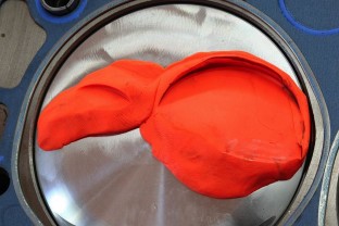
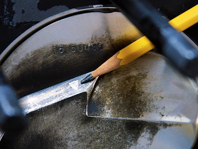
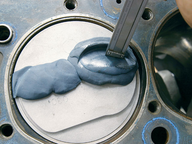
inspect carefully and use modeling clay over the whole piston dome to verify potential piston to valve contact areas
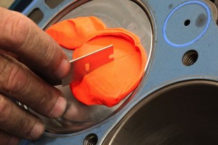
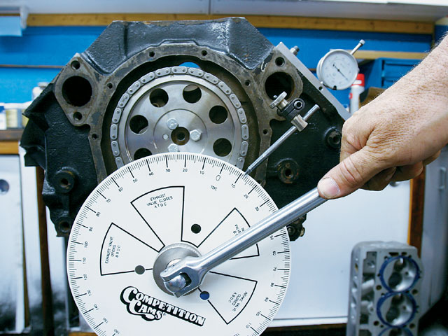
Position the cylinder head on the block and use enough head bolts to tighten snugly. Install the lifters and pushrods. If the engine is to be built with hydraulic lifters, they cannot be used for checking clearances. Hydraulic lifters will bleed down and corrupt the measurements using both the clay or indicator methods. A solid lifter must be used for measurements. Install the rocker arms and zero the valve lash. Finger-tight is okay for securing the rocker arm. Note the checker springs. Regular valve springs can be used for the clay method, but it’s much tougher to rotate the crank. With a ratchet and crank socket--or in our case, the timing wheel--rotate the crankshaft in the normal direction several times to ensure that the valves make a good clean impression in the clay. Remember, it takes two crankshaft rotations to completely rotate the camshaft once. There’s a chance the clay may adhere to a valve, so carefully remove the cylinder head so that the clay is not disturbed. Now you can observe the distinct impressions in the clay on top of the piston. Use a razor blade or thin, sharp knife to cut carefully through the center of the impression made by the intake valve.
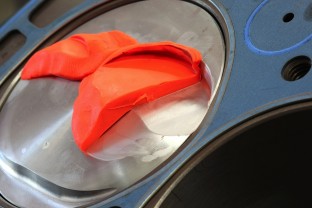
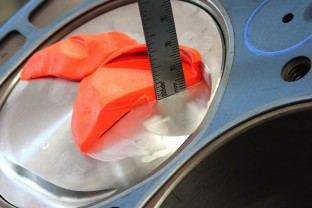
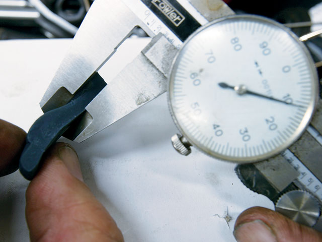
Carefully lift away the outer half of the clay to reveal the clearance between the piston and valve. Use a machinist’s scale or the depth probe on a dial caliper to get an accurate measurement of piston to valve clearance at the thinnest area of the clay impression.
check clearances especially radial or edge to valve pocket clearances carefully , I try for .100" -to-.120" on both intake and exhaust but Ive run engines with as little as .080 at times with no problems
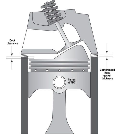
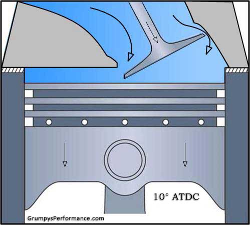
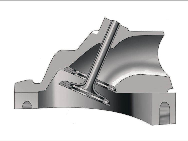
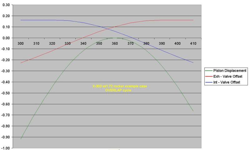
keep in mind that the intake valve usually starts to open well before the piston reaches TDC on its exhaust stroke, and continues to extend out towards the piston after it passes TDC and follows it down into the bore as it descends on the intake stroke, generally closest contact points are in the 20 degees btdc too 20 degrees atdc, obviously exact potential clearances are dependent on both cam timing and cam indexing
it should be rather obvious that youll need to know the exact distance the piston deck sits at TDC ,above or below the block deck surface and the valve notch recess or pop-up dome volume of the piston to do accurate quench or compression calculations
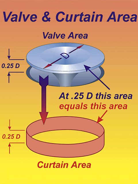
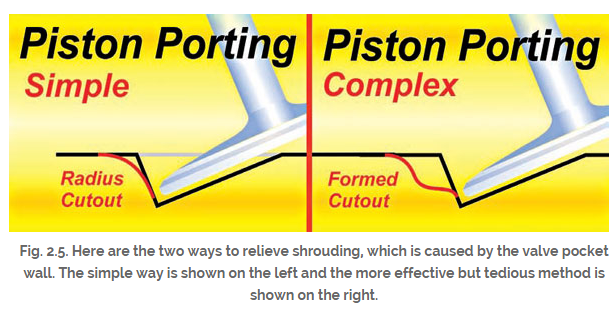
keep in mind any valve clearance recessed areas must have the areas shrouding flow blended to increase rather than restrict air flow and to reduce the potential for detonation that sharp exposed edges tend to have
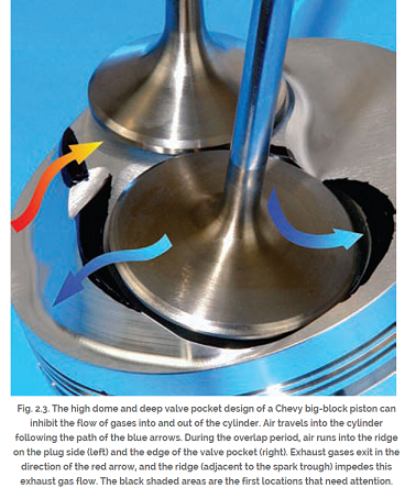
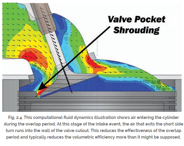
http://www.centuryperformance.com/check ... g-144.html
http://findarticles.com/p/articles/mi_q ... _n9406663/
http://victorylibrary.com/mopar/rod-tech-c.htm
http://victorylibrary.com/mopar/piston_position-c.htm
http://pcmofnc.com/index.php?option=com ... &Itemid=56
http://www.carcraft.com/howto/116_0701_ ... index.html
http://video.google.com/videosearch?sou ... &ct=title#
IF your like most guys you wonder how a cam can have a .600-.700 plus lift and theres obviously no way theres sufficient piston to valve clearance with the piston at TOP DEAD CENTER... TDC in its stroke,
keep in mind that the valve never reaches its full lift figures until the pistons between .400"-.800" away from TDC,
heres a typical radical cam s index card
http://www.cranecams.com/?show=browsePa ... e=camshaft
opens Closes Max Lift Duration
Intake 25.0 BTDC 53.0 ABDC
max lift near 104degs past tdc
103 258.0 °
Exhaust 65.0 BBDC 21.0 ATDC 113 266.0 °
max lift near 68degs past bdc

http://www.chevyhiperformance.com/techa ... ewall.html
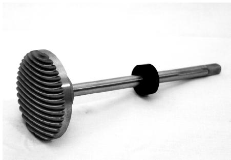
isky cams sells piston notching tools
read thru these LINKS CAREFULLY
IF your looking for a quick answer on whats the correct valve to piston clearance, Ive seen guys get by with as tight as .060 intake/.090 exhaust, but in my opinion thats rather tight and allows little to no safety if you ever get into valve float , and you can be 100% certain youll bust parts, miss a shift or get into condition's of valve float eventually, if you race the car.
its just a mater of time before you do.
Ive always tried for .100 intake/.120 exhaust
http://www.centuryperformance.com/check ... g-144.html
http://www.racingheadservice.com/Inform ... arance.asp
http://www.cdxglobal.com/content/sample ... ear_WS.pdf
http://www.chevyhiperformance.com/techa ... index.html
http://www.carcraft.com/howto/116_0701_ ... index.html
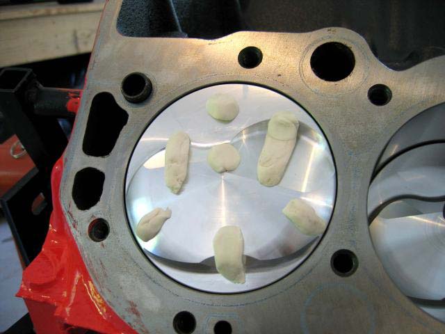
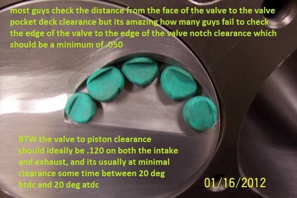
if your using the low pressure check springs its best to roll clay into several 1/4" diam. 3" long strips, resembling soda straws and lay several parallel across the piston valve notches as its far easier to compress that a solid layer of clay. strips tend to work better than small blobs like this picture below, spray both the piston and clay strips with WD40 to prevent sticking
if your thinking, well my new cam has only a bit more lift and duration than the current cam I don,t need to verify clearances, keep in mind pistons vary a good deal in shape as do valve angles so clearance issues are common, do yourself a favor and verify clearances before you start busting parts, by making random assumptions
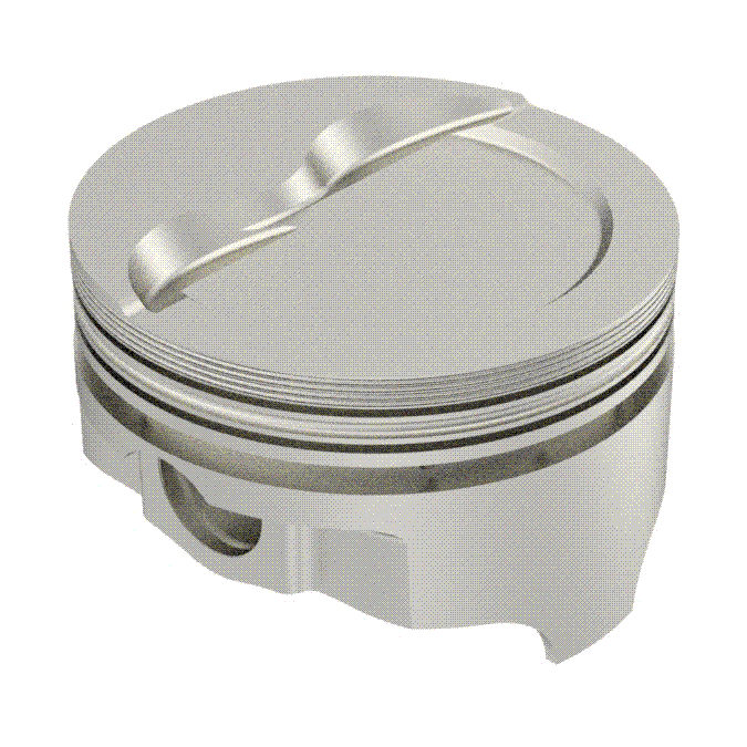
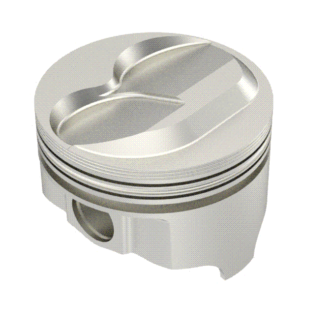
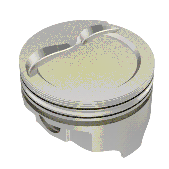
GRAPH SHOWING VALVE AND PISTON LOCATION, ,USUALLY AT ITS CLOSEST BETWEEN 10-20 DEGREES BFTDC and USUALLY AT ITS CLOSEST BETWEEN 10-20 DEGREES AFTDC

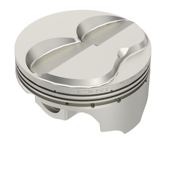
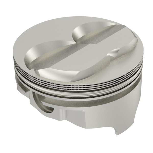
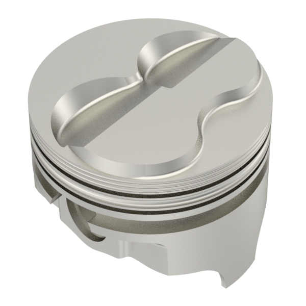
ISKY CAMS SELLS CUTTERS LIKE THIS TO NOTCH PISTONS

I still use the strips of modeling clay about 1" square and .2-.25" (two tenths too a 1/4" thick) but one thing everyone forgot to mention so far is that you need to spray the piston and valve and clay strips with WD-40 to ensure the clay does not stick to any parts, otherwise the clay will tend to stick to the valve and piston allowing them to push the clay between them during the compression of its surface by the valve (exactly what its there for) and PULL ON THE SURFACE of the clay as the valve moves away during separation (because the clay tends to stick ever so slightly as the parts pull away from each other if you don,t)which tends to give a false slightly greater than correct clearance measurement
most people tend to tell me Im wrong about that until they try it both ways :grin: yeah the difference is usually minor but five to 10 thousands difference is not rare if the parts are clean and dry versus sprayed with an oil mist


don,t forget you check BOTH the depth the valve extends down into the valve notch on the piston and how close the radial outside edge of the valve extends out towards the edge of the valve clearance notch
CHANGE RESULT
Advance cam timing Decreases intake valve-to-piston clearance, increases exhaust valve-to-piston clearance
Retard cam timing Decreases exhaust valve-to-piston clearance, increases intake valve-to-piston clearance
VALVE-TO-PISTON SPECS
Intake and exhaust: Minimum 0.100-inch depth clearance preferred
Minimum 0.050-inch radially
Piston dome to head: 0.050-inch minimum*
Piston to spark plug: 0.050-inch minimum*
*Steel-connecting-rod engines only
Variables That Affect VALVE-TO-Piston Clearance
Intake center line (cam position)
Duration
Valve lift
Rocker ratio
Valve diameter
Piston top (domed, dish, or flat)
Shape and angle of piston valve reliefs
Valve angle
Piston deck height
Head-gasket thickness
Valve float at high rpm (loss of spring control)
Pushrod deflection at high rpm
Angle milling heads
One of the easiest and quickest methods thats a bunch
more accurate than the clay-method , would be to use
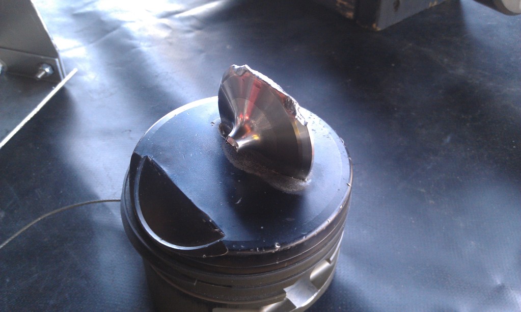
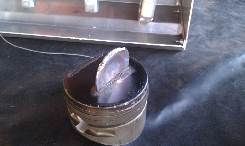
Acid-core solder (usually .120" thick )
or
Resin-core solder (usually .090" thick )
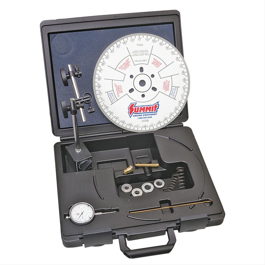
if your wondering how to turn a crank over to do test and diagnosing and cam installs you will benefit from the proper tools
IF you remove the spark plugs and take the car out of gear its fairly safe to turn the engine over manually,
using a breaker bar on the cranks damper retainer bolt,the problem is 99.9% of us are LAZY,
and just try it as the engine sits and eventually we strip the crank bolt or the crank snout threads
If the damper been removed the crank snout socket thats designed for your crank to turn the crank.
and hold the degree wheel while degreeing in the cam will be the route to take
shop carefully and ask questions the sockets and tools don,t fit universally, you'll need an assortment of several OF EACH TYPE ONCE YOU GET INTO ENGINE BUILDING SERIOUSLY
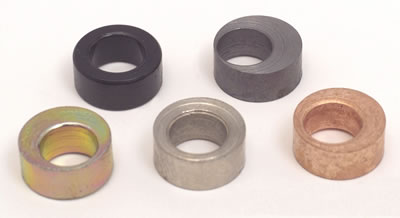
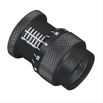
the crank socket like this that can turn the crank safely and firmly and accuratly mount a degree wheel is prefered
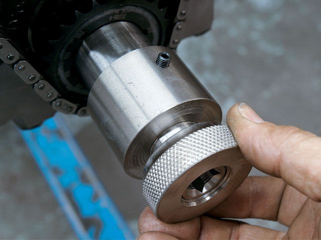
there are also crank turning nuts that fit individual crank sizes
most of us are too lazy to remove the damper/balancers
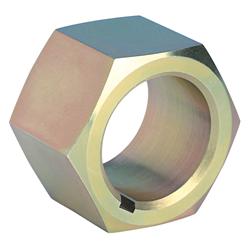
there are over size extra strength damper bolts for sale that are less likely to strip
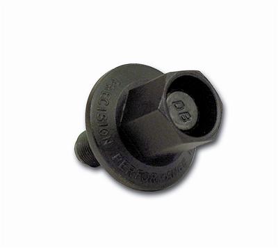
they sell an engine damper bolt on tool that fits some dampers that allows you to use a 1/2" braker bar rather easily
http://www.summitracing.com/parts/pro-66782?seid=srese1&gclid=CNqD0YXA48gCFUYYHwodBJ4DVA
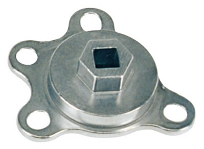
IT MAKES LITTLE SENSE TO BUY the sockets that don.t have the provision for mounting the cam degree wheel to save a few dollars in my opinion
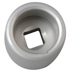
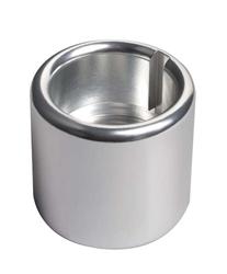
READ THESE LINKS
http://www.fordmuscle.com/fundamentals/pistontovalve/index.shtml
http://garage.grumpysperformance.com/index.php?threads/bare-minimum-tools.11026/#post-48796
With the solder-method , you don't actually need a degree wheel
..just the harmonic balancer timing marks and a 6" dial caliper
Turn the engine over till you are coming up to TDC-Overlap
with both the exhaust valve on its way to closing, and
the intake valve beginning to open
Turn the engine till you are about 1/2 inch from TDC ,
then roll out and straighten a piece of acid-core solder about
6 to 8 inches long ....then with headers off , look thru
#1 Cylinder's exhaust port with a pen lite...take the solder
and place it thru the spark plug hole , placing solder
across the Exhaust valve piston notch...then hold solder at that
angle while someone slowly turns engine over to TDC-Overlap
and then past TDC until you "feel" you can pull out solder .
as you turn the engine over at TDC the exhaust valve will
touch or squeeze the solder to the valve-to-piston clearance
...as you keep turning engine past TDC-Overlap,
the solder will be released
remove the solder and look for indentation ...measure with
dial-caliper ..and this is the valve-to-piston clearance !
No clay mess , no clay spring-back , very much accurate than clay-method
Cut a new piece of solder ...and just repeat for intake side !
Note=>can use solder method to check total deck heights accurately !
----------------------------------------------------------------------
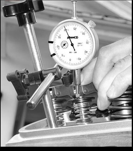
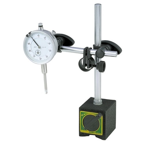
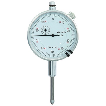
the best method would be to use a 1.000" dial indicator and
magnetic stand ....bolt a 1/8 thick small plate to valve cover
bolt hole then stick the indicator in place on the steel plate .
(sometimes a SBC fuel-pump cover works great)
attach a degree wheel and pointer and find true TDC ,
then turn engine over till 10 degrees BEFORE TDC-Overlap
to measure Exhaust clearance . (8 -to- 12 deg closest points)
at 10 deg BTDC ...place the 1.000" dial indicator's point on
the flat part of the spring retainer , zero the indicator,
and with the set-screw backed out of the adjuster nut, take
a wrench and turn the adjuster nut till you force the valve to
bottom out against the piston's exhaust notch ....read how much
the dial indicator traveled ...that's your Exhaust clearance
back-off Exhaust adjuster nut back to ZERO point on dial indicator
now, repeat the same procedure on the Intake side ...but this
time turn engine past TDC-Overlap to 10 degrees AFTER TDC
then check Intake clearance .
--------------------------------------------------------------------------
Note : You should always check valve-to-piston clearance with
a fully assembled valvetrain with the real springs in place
and every rocker lashed ...and ONLY turning the engine over in
the direction of rotation (ClockWise).
using light checker type springs will make you flycut pistons
approx. .030" more than necessary ...in other words, what ever
valve-to-piston clearance you check with lite-springs, when the
engine is fully assembled with the real springs, it will have
approx. .030" more clearance !
using lite-checker springs will be a "SAFER" way to check and will
be a good method to use for a beginner engine builder !!!
-------------------------------------------------------------------------
A professional engine builder would use the real springs and watch this
effect upon the cam-twist, Jesel belt distortion, push rod flex , ETC.
A professional engine builder would check each and every Cylinder's
clearance..and have detailed computer records of things like
1- Piston Intake and Exhaust fly cut valve notch depth
2- Piston Valve notch fly cut radius , angle + tilt, center-to-bore location
3- Intake and Exhaust valve seat depths on heads, valve margins, etc.
and other things like
4- Total Valve-Notch-Depths
to check the Total Notch Depths ...just place each piston at TDC ,
then place dial indicator zeroed on the top of the valve stem ,
push the valve down till it rests ontop of the piston notch ,
then record this distance !
(need to have springs off , and 2 rubber O-Rings holding up valve
in guides ...when you go to check distance)
As you gain experience and information, you can easily know in advance
what the ballpark valve-to-piston clearance will be with known cam lobes and
rocker ratios , along with cylinder head's valve depth readings , and
piston flycut data .
I try for 0.080 on the intake and 0.100 on the exhaust as absolute minimums but am far happier with 0.120 thousands (just under 1/8") or greater on both!
Ill always trade increased clearance to gain reliability for a slight loss in compression,keep in mind that if you get to tight on those clearances you will be locked into that cam timing and dropping it back (RETARDING the cam) for greater high rpm power or (advancing the cam) for more low rpm torque becomes next to impossible in some cases while you tune the engine combo!

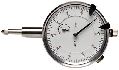
"you'll need to consistently measure the piston quench area and the wrist pin center-line heights on the pistons, keeping in mind that rod and pistons dimensions vary slightly so you'll want to mix/match to minimize the combined differences, placing taller pin height pistons on shorter rods, etc."
pistons can and do rock in the bore very slightly so if you want the most consistent measurements between cylinders , youll use the yellow dot or center of the piston over the pin bore center line,and rock the piston on both edges measuring 90 degrees from the pin center line and average the two results, just be aware that your quench distance can change when the piston rocks slightly at higher rpms as theres definitely a thrust side and ring drag so the piston doesn,t always remain exactly strait in the bore center line
RELATED INFO
http://www.islandblue.com/store/product ... -ASSORTED/
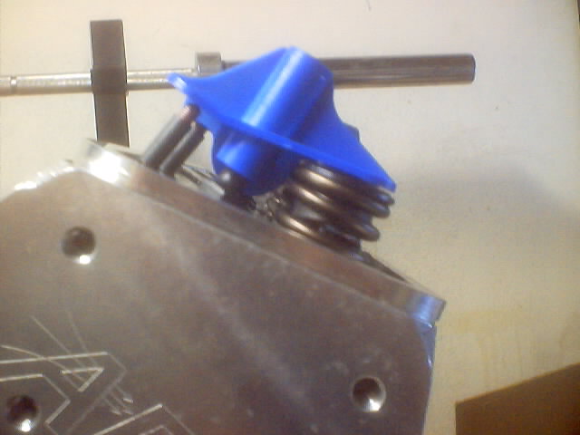
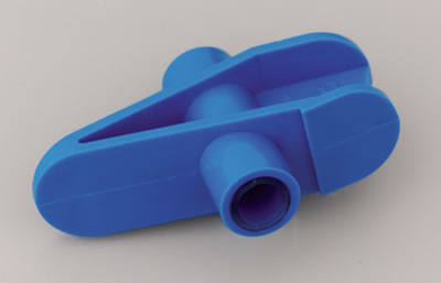
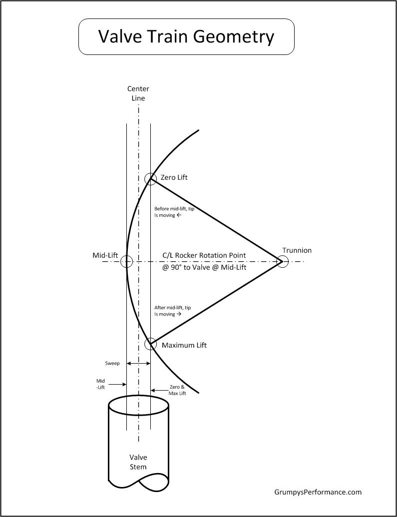
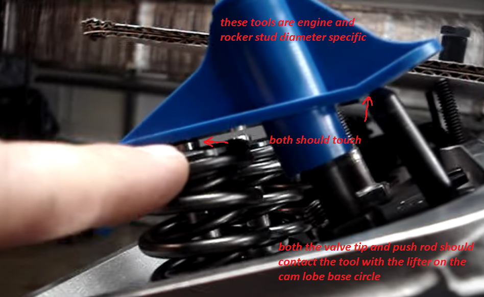
Proper push rod length is absolutely critical for peak performance—minimizing bent or broken valve stems, guide wear, and energy-wasting valve side-loading friction. IF YOU CHANGE VALVE TRAIN COMPONENTS VERIFY YOUR ROCKER GEOMETRY, AND ALL RELATED CLEARANCE ISSUES
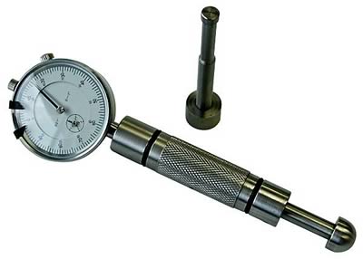
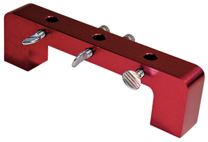
With the lifter located on the round base circle, position the Push Rod length Checker (make sure you have the Checker with the proper diameter hole) over the stud. Ideally the Checker should contact the top of the push rod and the valve tip evenly at the same moment, should the Checker contact the push rod first, measure the gap between the front of the checker and the valve tip, and purchase a shorter push rod of the correct length. Should the Checker contact the valve tip first, measure the gap between the back of the Checker and the top of the push rod, and purchase a longer push rod
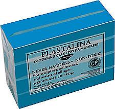
I don,t know many or in fact any engine builder that doesn,t have some good model clay in his tool box for checking clearances
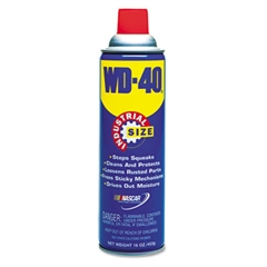
or a can of wd 40 to spray on the valves and clay too prevent clay sticking to parts measured, use good quality modeling clay, some crap like kids PLAY DOW, is SPRINGY and won,t give exact and consistent measurements, I pick mine up at a local arts & craft supply

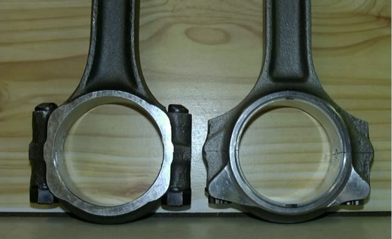
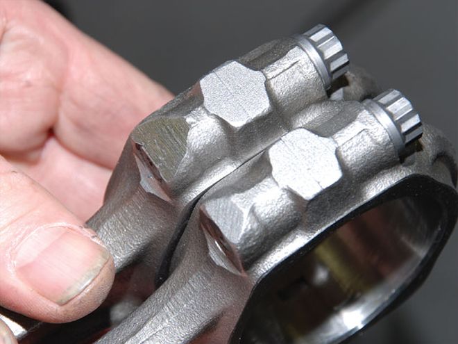
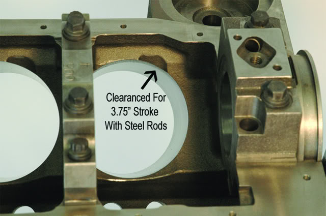
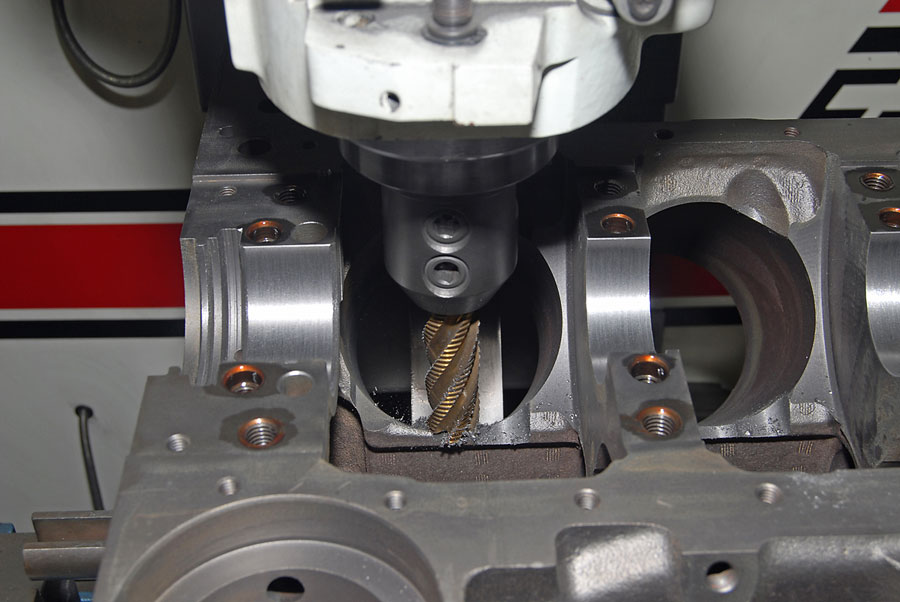
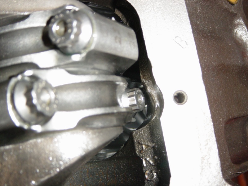
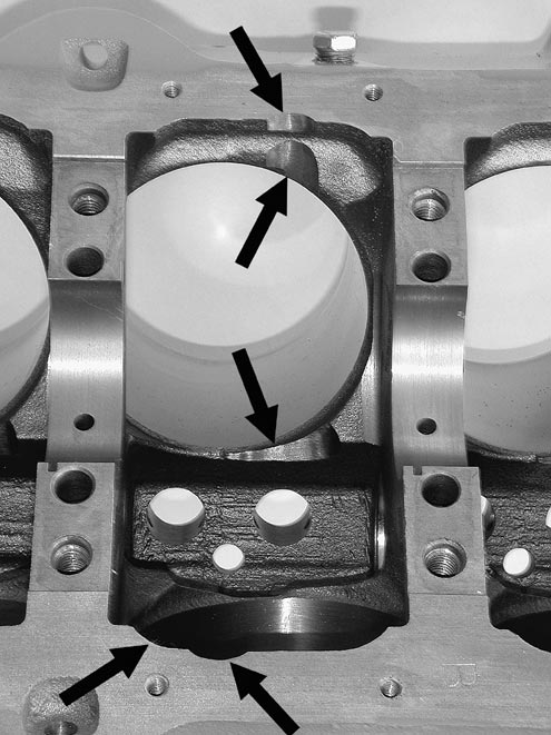
the cam rotates while indexed by the timing chain at 1/2 crank shaft speed , there are connecting rods designed to provide additional clearance.
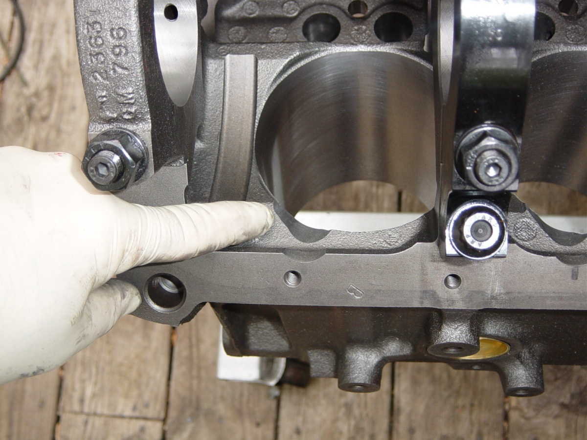
http://www.scatcrankshafts.com/index.htm
don,t forget to verify the cam to connecting rod clearances
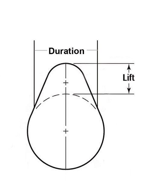
a cams VALVE LIFT is determined by the DISTANCE the lifter moves as the cam rotates under the lifter base as it moves from the cam lobe base circle
(the closest the lifter comes to the cams center line)
up to the cam lobes ramp to the lobes peak,
(the furthest the lifter up off or from the cams center line)
your cams lift, is the result of the lifter movement, or distance it travels from the cams base circle, where the valves seated, to the point in the cams rotation where the lifters moved along the ramp surface fully up on the nose of the cam lobe where the valves at full lift.
example
lets say in this case we compare two imaginary cams
a standard cams base circle is 1.125" and
your cams running on a .900 base circle
both cams have a .560 valve lift and run with 1.5:1 rockers
so both cams will need to move the lifter .374"
that means the standard cam lobe will be 1.125"+.374" or 1.499" from the cams base to the cam lobe nose
that means the small base cam lobe will be .900"+.374" or 1.274" from the cams base to the cam lobe nose
which is significantly smaller,
small base circle cams are generally only used when connecting rod clearance necessitates there use
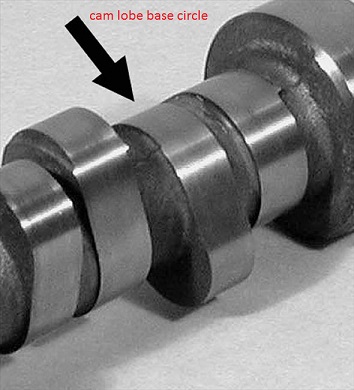
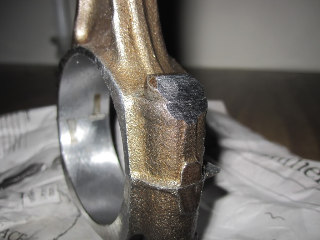
the BASE CIRCLE IS NEVER A CLEARANCE ISSUE, its the cam LOBES that can potentially contact the edge of the connecting rods or bolts, this is why the rods or rod bolts are machined for additional clearance for the cam lobes as you rather obviously CAN,T machine the cam lobes themselves without destroying their function.
now think about it for a few seconds
the cams lobe lift and the cams LSA or LOBE SEPARATION ANGLE
both have an effect on the cam lobes potential interference with the connecting rods
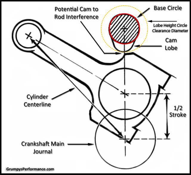
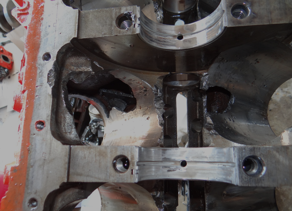
notice how the rod bolts come close to the cam bearings as the pistons reach top dead canter in the bores
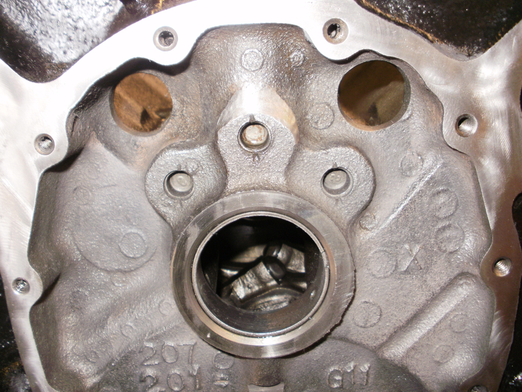
RODS WELL AWAY FROM CAM LOBES
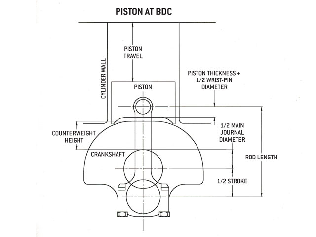
RODS CLOSE TO CAM LOBES
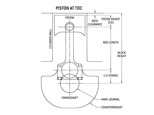
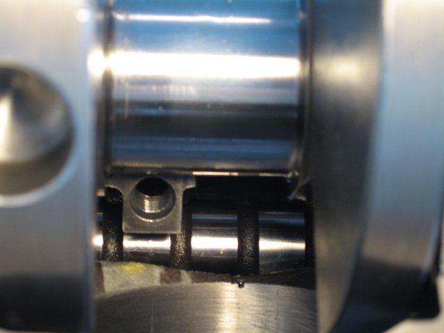
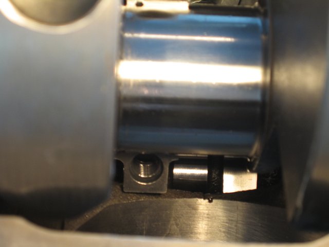
WITH THE CORRECT SOFT WARE BOTH THE PISTON TO VALVE CLEARANCE AND CAM TO ROD CLEARANCE CAN BE CALCULATED
BUT ANY COMPETENT ENGINE BUILDER WILL PHYSICALLY VERIFY CLEARANCE

http://garage.grumpysperformance.com/index.php?threads/virtual-dyno-software.2301/#post-53646
http://www.auto-ware.com/software/eap/eap.htm
rods designed like the 3 SERIES generally won,t work with stroker cranks while the 2 series usually will
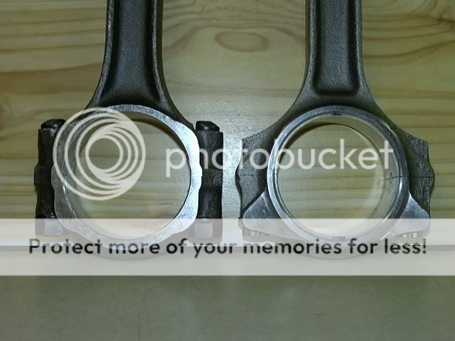
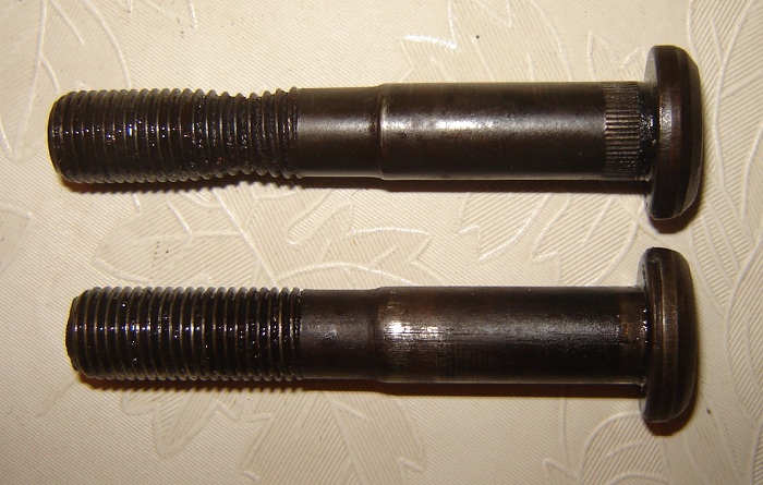
the connecting rods you sellect make a huge differance in the rod to cam lobe clearance, even a small base cam won,t clear some designs, it should be obvious that the connecting rod with the thru bolt has a great deal less cam lobe clearance potentially than the cap screw design next to it., and the cap screw rod probably clears the blocks oil pan rail area easier also
measuring piston dome volume
\" how do you measure piston dome volume" I just bought a 454 from a yard sale, the seller has no clue as to the pistons used" https://www.summitracing.com/newsandevents/calcsandtools/compression-calculator http://www.grumpysperformance.com/cop2.png...
garage.grumpysperformance.com


Valve To Piston Clearance??
A buddy of mine is about to drop off a set of fresh 215 closed chambered heads that I’m getting for next to nothing. Question here is does anyone know if the 2349 speed pro ls6 closed chamber replacement piston will work with them? I have a short block sitting here with those pistons ready to go...
garage.grumpysperformance.com

if you have a minimum of .120 on both the intake and exhaust valve on that #1 and #2 cylinder (one on each bank) I think youll be ok, measuring just that cylinder , if either the intake or exhaust valve has less than .100 ID measure all the cylinders just to be sure!
don,t forget to verify the valve edge to valve pocket clearance along with the valve face too piston deck clearances
READ THESE THREADS
http://garage.grumpysperformance.co...op-dead-center-1-for-timing-ignition-cam.966/
http://garage.grumpysperformance.co...ring-installation-questions.12833/#post-66460
http://garage.grumpysperformance.co...-pushrods-and-check-info-you-might-need.5931/
http://garage.grumpysperformance.com/index.php?threads/valve-train-clearances-and-problems.528/
http://garage.grumpysperformance.co...ectly-and-get-it-to-last-cam-install-info.90/
http://garage.grumpysperformance.com/index.php?threads/how-to-read-a-cam-spec-card.1477/
http://garage.grumpysperformance.co...ve-spring-bind-height-060-safety-margin.4957/
http://garage.grumpysperformance.com/index.php?threads/special-lifter-for-checking-cam-timing.3745/
http://garage.grumpysperformance.com/index.php?threads/valve-train-clearances-and-problems.528/
http://garage.grumpysperformance.co...e-springs-and-setting-up-the-valve-train.181/
http://garage.grumpysperformance.com/index.php?threads/can-you-plan-for-quench.11298/
http://garage.grumpysperformance.com/index.php?threads/head-gasket-related.1859/#post-50617
http://garage.grumpysperformance.com/index.php?threads/quench-or.10951/
http://garage.grumpysperformance.co...r-piston-dome-or-port-volume.2077/#post-44568
http://garage.grumpysperformance.co...needs-clean-up-equalization.12474/#post-62647
http://garage.grumpysperformance.co...ng-combustion-chambers.2630/page-2#post-55199
DON"T FORGET TO VERIFY SPRING BIND CLEARANCE AND PISTON TO VALVE CLEARANCE ETC>


be sure you, measure EACH bore and EACH piston,
(CORRECTLY with the proper tools in the way the tool and piston manufacturers suggested)
and number them on an engine build sheet indicating the bore and piston diam.
from large to smallest on each and install them on each cylinder to get the most consistent piston to bore clearance's
yes the difference may only be a few ten thousands if the bores are machined correctly, but you'll get the best results , most consistent lubrication, best durability and less heat build up that might result in detonation issues that way. its the little things that add up to making a good durable engine assembly,
BTW check rod orientation, so the beveled sides don't fact the adjacent rods, and check the bearing clearances with plasti guage
every part you choose is a compromise , and may require changes,
that cost you in time, money or performance to some degree,
and almost every part will require a bit of fitting or clearance work,
or adjustment to fit and function to get the best results
if it drops out of the package and bolts together as it drops out of the package,
its almost certain its not functional to nearly its full potential
your job is to think things through carefully and make sure parts fit and function to their full potential,
little things like checking piston ring end gap, verifying bearing clearances, and ccing the heads and checking piston to valve clearance, degreeing in the cam and verifying the valve train geometry, polishing combustion chambers, getting a decent 3 angle valve job,verifying the piston to bore clearance, MATTER's

READ THIS THREAD AND RELATED LINKED INFO
http://garage.grumpysperformance.co...rdering-correct-custom-length-pushrods.14241/
this is a common warning posted , on the subject of checking piston to valve clearance, this is from AFR website
if the end user builds an engine without properly verifying he has enough piston to valve clearance (depth and radial clearance both checked). We recommend a minimum depth of .080 on the intake valve and .100 on the exhaust with a radial clearance of .200 minimum around the perimeter of each valve. Clay is recommended to visually verify both depth as well as radial clearance. Just checking depth is not enough...the position of the valve pocket must also be addressed.


it should be rather obvious that youll need to know the exact distance the piston deck sits at TDC ,above or below the block deck surface and the valve notch recess or pop-up dome volume of the piston to do accurate quench or compression calculations
heres a few links with that info.
like always reading thru all the links gives you much more complete info...


you need .090 clearance between the retainer to valve seal and a TOTAL of .060 clearance MINIMUM on the valve spring coils from spring bind, or solid stacking the spring coils


inspect carefully and use modeling clay over the whole piston dome to verify potential piston to valve contact areas
Position the cylinder head on the block and use enough head bolts to tighten snugly. Install the lifters and pushrods. If the engine is to be built with hydraulic lifters, they cannot be used for checking clearances. Hydraulic lifters will bleed down and corrupt the measurements using both the clay or indicator methods. A solid lifter must be used for measurements. Install the rocker arms and zero the valve lash. Finger-tight is okay for securing the rocker arm. Note the checker springs. Regular valve springs can be used for the clay method, but it’s much tougher to rotate the crank. With a ratchet and crank socket--or in our case, the timing wheel--rotate the crankshaft in the normal direction several times to ensure that the valves make a good clean impression in the clay. Remember, it takes two crankshaft rotations to completely rotate the camshaft once. There’s a chance the clay may adhere to a valve, so carefully remove the cylinder head so that the clay is not disturbed. Now you can observe the distinct impressions in the clay on top of the piston. Use a razor blade or thin, sharp knife to cut carefully through the center of the impression made by the intake valve.


Carefully lift away the outer half of the clay to reveal the clearance between the piston and valve. Use a machinist’s scale or the depth probe on a dial caliper to get an accurate measurement of piston to valve clearance at the thinnest area of the clay impression.
check clearances especially radial or edge to valve pocket clearances carefully , I try for .100" -to-.120" on both intake and exhaust but Ive run engines with as little as .080 at times with no problems


keep in mind that the intake valve usually starts to open well before the piston reaches TDC on its exhaust stroke, and continues to extend out towards the piston after it passes TDC and follows it down into the bore as it descends on the intake stroke, generally closest contact points are in the 20 degees btdc too 20 degrees atdc, obviously exact potential clearances are dependent on both cam timing and cam indexing
it should be rather obvious that youll need to know the exact distance the piston deck sits at TDC ,above or below the block deck surface and the valve notch recess or pop-up dome volume of the piston to do accurate quench or compression calculations

keep in mind any valve clearance recessed areas must have the areas shrouding flow blended to increase rather than restrict air flow and to reduce the potential for detonation that sharp exposed edges tend to have


http://www.centuryperformance.com/check ... g-144.html
http://findarticles.com/p/articles/mi_q ... _n9406663/
http://victorylibrary.com/mopar/rod-tech-c.htm
http://victorylibrary.com/mopar/piston_position-c.htm
http://pcmofnc.com/index.php?option=com ... &Itemid=56
http://www.carcraft.com/howto/116_0701_ ... index.html
http://video.google.com/videosearch?sou ... &ct=title#
IF your like most guys you wonder how a cam can have a .600-.700 plus lift and theres obviously no way theres sufficient piston to valve clearance with the piston at TOP DEAD CENTER... TDC in its stroke,
keep in mind that the valve never reaches its full lift figures until the pistons between .400"-.800" away from TDC,
heres a typical radical cam s index card
http://www.cranecams.com/?show=browsePa ... e=camshaft
opens Closes Max Lift Duration
Intake 25.0 BTDC 53.0 ABDC
max lift near 104degs past tdc
103 258.0 °
Exhaust 65.0 BBDC 21.0 ATDC 113 266.0 °
max lift near 68degs past bdc

http://www.chevyhiperformance.com/techa ... ewall.html

isky cams sells piston notching tools
read thru these LINKS CAREFULLY

IF your looking for a quick answer on whats the correct valve to piston clearance, Ive seen guys get by with as tight as .060 intake/.090 exhaust, but in my opinion thats rather tight and allows little to no safety if you ever get into valve float , and you can be 100% certain youll bust parts, miss a shift or get into condition's of valve float eventually, if you race the car.
its just a mater of time before you do.
Ive always tried for .100 intake/.120 exhaust
http://www.centuryperformance.com/check ... g-144.html
http://www.racingheadservice.com/Inform ... arance.asp
http://www.cdxglobal.com/content/sample ... ear_WS.pdf
http://www.chevyhiperformance.com/techa ... index.html
http://www.carcraft.com/howto/116_0701_ ... index.html
if your using the low pressure check springs its best to roll clay into several 1/4" diam. 3" long strips, resembling soda straws and lay several parallel across the piston valve notches as its far easier to compress that a solid layer of clay. strips tend to work better than small blobs like this picture below, spray both the piston and clay strips with WD40 to prevent sticking

if your thinking, well my new cam has only a bit more lift and duration than the current cam I don,t need to verify clearances, keep in mind pistons vary a good deal in shape as do valve angles so clearance issues are common, do yourself a favor and verify clearances before you start busting parts, by making random assumptions


GRAPH SHOWING VALVE AND PISTON LOCATION, ,USUALLY AT ITS CLOSEST BETWEEN 10-20 DEGREES BFTDC and USUALLY AT ITS CLOSEST BETWEEN 10-20 DEGREES AFTDC


ISKY CAMS SELLS CUTTERS LIKE THIS TO NOTCH PISTONS

I still use the strips of modeling clay about 1" square and .2-.25" (two tenths too a 1/4" thick) but one thing everyone forgot to mention so far is that you need to spray the piston and valve and clay strips with WD-40 to ensure the clay does not stick to any parts, otherwise the clay will tend to stick to the valve and piston allowing them to push the clay between them during the compression of its surface by the valve (exactly what its there for) and PULL ON THE SURFACE of the clay as the valve moves away during separation (because the clay tends to stick ever so slightly as the parts pull away from each other if you don,t)which tends to give a false slightly greater than correct clearance measurement
most people tend to tell me Im wrong about that until they try it both ways :grin: yeah the difference is usually minor but five to 10 thousands difference is not rare if the parts are clean and dry versus sprayed with an oil mist


don,t forget you check BOTH the depth the valve extends down into the valve notch on the piston and how close the radial outside edge of the valve extends out towards the edge of the valve clearance notch
CHANGE RESULT
Advance cam timing Decreases intake valve-to-piston clearance, increases exhaust valve-to-piston clearance
Retard cam timing Decreases exhaust valve-to-piston clearance, increases intake valve-to-piston clearance
VALVE-TO-PISTON SPECS
Intake and exhaust: Minimum 0.100-inch depth clearance preferred
Minimum 0.050-inch radially
Piston dome to head: 0.050-inch minimum*
Piston to spark plug: 0.050-inch minimum*
*Steel-connecting-rod engines only
Variables That Affect VALVE-TO-Piston Clearance
Intake center line (cam position)
Duration
Valve lift
Rocker ratio
Valve diameter
Piston top (domed, dish, or flat)
Shape and angle of piston valve reliefs
Valve angle
Piston deck height
Head-gasket thickness
Valve float at high rpm (loss of spring control)
Pushrod deflection at high rpm
Angle milling heads
One of the easiest and quickest methods thats a bunch
more accurate than the clay-method , would be to use
Acid-core solder (usually .120" thick )
or
Resin-core solder (usually .090" thick )
if your wondering how to turn a crank over to do test and diagnosing and cam installs you will benefit from the proper tools
IF you remove the spark plugs and take the car out of gear its fairly safe to turn the engine over manually,
using a breaker bar on the cranks damper retainer bolt,the problem is 99.9% of us are LAZY,
and just try it as the engine sits and eventually we strip the crank bolt or the crank snout threads
If the damper been removed the crank snout socket thats designed for your crank to turn the crank.
and hold the degree wheel while degreeing in the cam will be the route to take
shop carefully and ask questions the sockets and tools don,t fit universally, you'll need an assortment of several OF EACH TYPE ONCE YOU GET INTO ENGINE BUILDING SERIOUSLY
the crank socket like this that can turn the crank safely and firmly and accuratly mount a degree wheel is prefered

there are also crank turning nuts that fit individual crank sizes
most of us are too lazy to remove the damper/balancers

there are over size extra strength damper bolts for sale that are less likely to strip

they sell an engine damper bolt on tool that fits some dampers that allows you to use a 1/2" braker bar rather easily
http://www.summitracing.com/parts/pro-66782?seid=srese1&gclid=CNqD0YXA48gCFUYYHwodBJ4DVA

IT MAKES LITTLE SENSE TO BUY the sockets that don.t have the provision for mounting the cam degree wheel to save a few dollars in my opinion


READ THESE LINKS
http://www.fordmuscle.com/fundamentals/pistontovalve/index.shtml
http://garage.grumpysperformance.com/index.php?threads/bare-minimum-tools.11026/#post-48796
With the solder-method , you don't actually need a degree wheel
..just the harmonic balancer timing marks and a 6" dial caliper
Turn the engine over till you are coming up to TDC-Overlap
with both the exhaust valve on its way to closing, and
the intake valve beginning to open
Turn the engine till you are about 1/2 inch from TDC ,
then roll out and straighten a piece of acid-core solder about
6 to 8 inches long ....then with headers off , look thru
#1 Cylinder's exhaust port with a pen lite...take the solder
and place it thru the spark plug hole , placing solder
across the Exhaust valve piston notch...then hold solder at that
angle while someone slowly turns engine over to TDC-Overlap
and then past TDC until you "feel" you can pull out solder .
as you turn the engine over at TDC the exhaust valve will
touch or squeeze the solder to the valve-to-piston clearance
...as you keep turning engine past TDC-Overlap,
the solder will be released
remove the solder and look for indentation ...measure with
dial-caliper ..and this is the valve-to-piston clearance !
No clay mess , no clay spring-back , very much accurate than clay-method
Cut a new piece of solder ...and just repeat for intake side !
Note=>can use solder method to check total deck heights accurately !
----------------------------------------------------------------------
the best method would be to use a 1.000" dial indicator and
magnetic stand ....bolt a 1/8 thick small plate to valve cover
bolt hole then stick the indicator in place on the steel plate .
(sometimes a SBC fuel-pump cover works great)
attach a degree wheel and pointer and find true TDC ,
then turn engine over till 10 degrees BEFORE TDC-Overlap
to measure Exhaust clearance . (8 -to- 12 deg closest points)
at 10 deg BTDC ...place the 1.000" dial indicator's point on
the flat part of the spring retainer , zero the indicator,
and with the set-screw backed out of the adjuster nut, take
a wrench and turn the adjuster nut till you force the valve to
bottom out against the piston's exhaust notch ....read how much
the dial indicator traveled ...that's your Exhaust clearance
back-off Exhaust adjuster nut back to ZERO point on dial indicator
now, repeat the same procedure on the Intake side ...but this
time turn engine past TDC-Overlap to 10 degrees AFTER TDC
then check Intake clearance .
--------------------------------------------------------------------------
Note : You should always check valve-to-piston clearance with
a fully assembled valvetrain with the real springs in place
and every rocker lashed ...and ONLY turning the engine over in
the direction of rotation (ClockWise).
using light checker type springs will make you flycut pistons
approx. .030" more than necessary ...in other words, what ever
valve-to-piston clearance you check with lite-springs, when the
engine is fully assembled with the real springs, it will have
approx. .030" more clearance !
using lite-checker springs will be a "SAFER" way to check and will
be a good method to use for a beginner engine builder !!!
-------------------------------------------------------------------------
A professional engine builder would use the real springs and watch this
effect upon the cam-twist, Jesel belt distortion, push rod flex , ETC.
A professional engine builder would check each and every Cylinder's
clearance..and have detailed computer records of things like
1- Piston Intake and Exhaust fly cut valve notch depth
2- Piston Valve notch fly cut radius , angle + tilt, center-to-bore location
3- Intake and Exhaust valve seat depths on heads, valve margins, etc.
and other things like
4- Total Valve-Notch-Depths
to check the Total Notch Depths ...just place each piston at TDC ,
then place dial indicator zeroed on the top of the valve stem ,
push the valve down till it rests ontop of the piston notch ,
then record this distance !
(need to have springs off , and 2 rubber O-Rings holding up valve
in guides ...when you go to check distance)
As you gain experience and information, you can easily know in advance
what the ballpark valve-to-piston clearance will be with known cam lobes and
rocker ratios , along with cylinder head's valve depth readings , and
piston flycut data .
I try for 0.080 on the intake and 0.100 on the exhaust as absolute minimums but am far happier with 0.120 thousands (just under 1/8") or greater on both!
Ill always trade increased clearance to gain reliability for a slight loss in compression,keep in mind that if you get to tight on those clearances you will be locked into that cam timing and dropping it back (RETARDING the cam) for greater high rpm power or (advancing the cam) for more low rpm torque becomes next to impossible in some cases while you tune the engine combo!


"you'll need to consistently measure the piston quench area and the wrist pin center-line heights on the pistons, keeping in mind that rod and pistons dimensions vary slightly so you'll want to mix/match to minimize the combined differences, placing taller pin height pistons on shorter rods, etc."
pistons can and do rock in the bore very slightly so if you want the most consistent measurements between cylinders , youll use the yellow dot or center of the piston over the pin bore center line,and rock the piston on both edges measuring 90 degrees from the pin center line and average the two results, just be aware that your quench distance can change when the piston rocks slightly at higher rpms as theres definitely a thrust side and ring drag so the piston doesn,t always remain exactly strait in the bore center line


RELATED INFO
http://www.islandblue.com/store/product ... -ASSORTED/


Proper push rod length is absolutely critical for peak performance—minimizing bent or broken valve stems, guide wear, and energy-wasting valve side-loading friction. IF YOU CHANGE VALVE TRAIN COMPONENTS VERIFY YOUR ROCKER GEOMETRY, AND ALL RELATED CLEARANCE ISSUES
With the lifter located on the round base circle, position the Push Rod length Checker (make sure you have the Checker with the proper diameter hole) over the stud. Ideally the Checker should contact the top of the push rod and the valve tip evenly at the same moment, should the Checker contact the push rod first, measure the gap between the front of the checker and the valve tip, and purchase a shorter push rod of the correct length. Should the Checker contact the valve tip first, measure the gap between the back of the Checker and the top of the push rod, and purchase a longer push rod
I don,t know many or in fact any engine builder that doesn,t have some good model clay in his tool box for checking clearances

or a can of wd 40 to spray on the valves and clay too prevent clay sticking to parts measured, use good quality modeling clay, some crap like kids PLAY DOW, is SPRINGY and won,t give exact and consistent measurements, I pick mine up at a local arts & craft supply


the cam rotates while indexed by the timing chain at 1/2 crank shaft speed , there are connecting rods designed to provide additional clearance.


http://www.scatcrankshafts.com/index.htm
don,t forget to verify the cam to connecting rod clearances
a cams VALVE LIFT is determined by the DISTANCE the lifter moves as the cam rotates under the lifter base as it moves from the cam lobe base circle
(the closest the lifter comes to the cams center line)
up to the cam lobes ramp to the lobes peak,
(the furthest the lifter up off or from the cams center line)
your cams lift, is the result of the lifter movement, or distance it travels from the cams base circle, where the valves seated, to the point in the cams rotation where the lifters moved along the ramp surface fully up on the nose of the cam lobe where the valves at full lift.
example
lets say in this case we compare two imaginary cams
a standard cams base circle is 1.125" and
your cams running on a .900 base circle
both cams have a .560 valve lift and run with 1.5:1 rockers
so both cams will need to move the lifter .374"
that means the standard cam lobe will be 1.125"+.374" or 1.499" from the cams base to the cam lobe nose
that means the small base cam lobe will be .900"+.374" or 1.274" from the cams base to the cam lobe nose
which is significantly smaller,
small base circle cams are generally only used when connecting rod clearance necessitates there use


the BASE CIRCLE IS NEVER A CLEARANCE ISSUE, its the cam LOBES that can potentially contact the edge of the connecting rods or bolts, this is why the rods or rod bolts are machined for additional clearance for the cam lobes as you rather obviously CAN,T machine the cam lobes themselves without destroying their function.
now think about it for a few seconds
the cams lobe lift and the cams LSA or LOBE SEPARATION ANGLE
both have an effect on the cam lobes potential interference with the connecting rods

notice how the rod bolts come close to the cam bearings as the pistons reach top dead canter in the bores


RODS WELL AWAY FROM CAM LOBES

RODS CLOSE TO CAM LOBES

WITH THE CORRECT SOFT WARE BOTH THE PISTON TO VALVE CLEARANCE AND CAM TO ROD CLEARANCE CAN BE CALCULATED
BUT ANY COMPETENT ENGINE BUILDER WILL PHYSICALLY VERIFY CLEARANCE

http://garage.grumpysperformance.com/index.php?threads/virtual-dyno-software.2301/#post-53646
http://www.auto-ware.com/software/eap/eap.htm
rods designed like the 3 SERIES generally won,t work with stroker cranks while the 2 series usually will
the connecting rods you sellect make a huge differance in the rod to cam lobe clearance, even a small base cam won,t clear some designs, it should be obvious that the connecting rod with the thru bolt has a great deal less cam lobe clearance potentially than the cap screw design next to it., and the cap screw rod probably clears the blocks oil pan rail area easier also
Last edited by a moderator:


