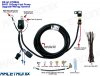
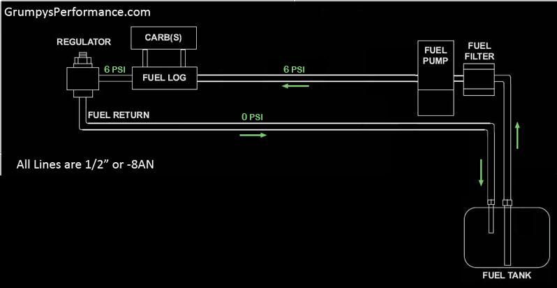
grumpyvette said:IVE ALWAYS PREFERRED THE LARGER AN#8 fuel line size
Did you use aluminum or steel fuel line ???
Do you have a source for 1/2" steel fuel line, all I can find is aluminum in 1/2" ???
grumpyvette said:IVE ALWAYS PREFERRED THE LARGER AN#8 fuel line size
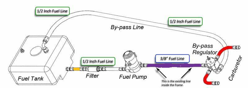
grumpyvette said:my current EFI 383 has a walpro 255 that provides 40 psi but uses 3/8" lines , and it will supply the required fuel to maintain about 500 hp.


grumpyvette said:please don,t think this comment is negative, its more of thought designed as a discussion starter on the subject,
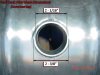
now not that it really matters a great deal in this application, but Im rather curious why you ran 3/8" tube 30" inside the frame at that point, I can see the potential for extra fuel line protection in the area from 15" behind the firewall to 15" in front where I usually use the EMT metal tube or a bit of 1" roll bar cage tube, to give a bit extra protection in case the blow proof bell housing fails in a clutch/flywheel failure/explosion, but back that far I don,t see the reason?? and I also don,t see the reason to reduce fuel line size before the fuel rail entrance.
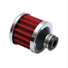
and yes the two quality fuel filter design, is a really good idea. but Id put some though into mount location and easy access, because you'll be replacing them occasionally and if possible access without needing a lift is a good idea.
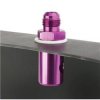
you might also consider a hidden but fairly accessible fuel line cut-off near the fuel tank, as it makes fuel filter swaps less messy and potentially dangerous from spilled fuel and its also a secondary security measure to make driving your car off without being authorized a far less doe-able deal for thieves


Indycars said:
The pumps usually draw less that 5 amps,
so just a switch is a possibility, eliminating $22.95 from the total cost.
grumpyvette said:I want every last thing on my car to be flawless
bytor said:I find it interesting that they recommend powering the fuel pump directly from the alternator terminal. I wonder how much benefit you would actually get doing it this way?

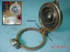
grumpyvette said:A few more detailed, pictures of what your doing as you progress with the fuel system instal or upgrades, would be great if your making any progress, on the car?
My main focus is the trans, but when I get held up for any reason, the fuel system is what I will do to stay busy. But at some point I will need the body and engine in place to move forward.
darn! I wish you (Indycars) and (DORIANL) , and several other members were all located within the immediate local area, theres so many times Id like to drop over and help out!
We need a retirement village with central shop with every tool possible available, with a Summit and Jegs warehouse just down the road for quick access to all the HP parts we need. Also they will give us a key in case we need something on Sunday or at 2 am in the morning.
Anything else you guys think we would need???