Civecam said:Hello all, been a while. I have been busy trying to get plans ready for our new house to be built and also working on my wife's vette, which leads to my question. Sorry for the book below.
I installed a FItech 1200 last year and for the most part it has been running pretty good once some of the tuning was worked out. (if you have one make sure you put in the correct timing number for the 4k offset). I had been running the FI coolant sensor in the passenger head and a Speedhut sensor in the driver head. They had been reading about 15 degrees different with the drivers around 185 and the passenger around 200. I decided to switch them to see if it made a difference to the FI. Now the FI reads 180 to 190 on the driver and the passenger follows it exactly to 180 degrees, sits there for a minute and then takes off to 215 at idle. I have used an IR gun to check and it the gauges seem to be reading correctly. If I have cruising at 3k RPM it goes to 205, but creeps back up as soon as I start idleing. If I turn the heater on it starts to go even higher. Before switching them the passenger side never went above 203 according to the handheld for the FiTech. I put the IR gun on the headers last night and all of them seemed to be in the 300 range at idle, but number 6 was about 100 higher. I pulled the plugs on 6, 8 and 5 and they all looked the same. Light tan to gray with the timing mark right at the bend.:huh:
Current parts on the car
Dewitts radiator
Edelbrock 8812 waterpump
zz4 shortblock
Dart 200 heads
10.5 compression
CC 288 HR cam
Fitech 122 EFI
MSD dizzy controlled by EFI
vintage air (not on when this is happening)
weiand xcelerator intake (actually works pretty good with the EFI, but I will probably be putting the RPM back on)
thoughts on cooling
sometimes things "stick" to the threads and just rip out and totally wreck the threads. Even when you use an Anti-Seize ? How about using an anti-seize and thread cleaner tap, run that thru there a several times before installing the anode. Here is a quick option...
garage.grumpysperformance.com
I found this posted on a different web site, hopefully it may help some guys
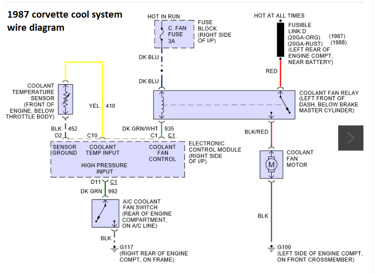
Let's start with your understanding first. To me, it's a fairly simple job except for the potential headache in tracking down where your factory wiring was cut. It COULD be hidden fairly well. Mostly, you just want to find the green/white wire going to your ECM.
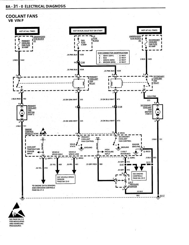
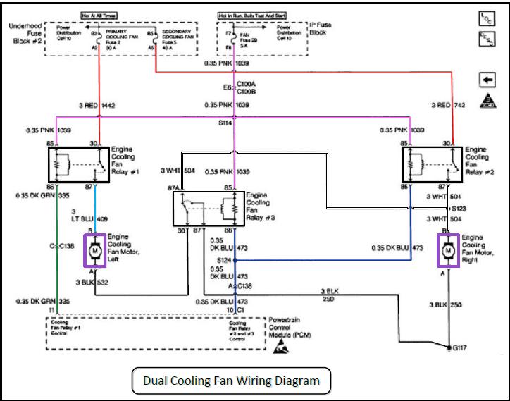
From here, I want to explain the diagram.
What you are looking at is the computer (ECM) in the middle. You can clearly see the fan motors on each side and the relays that "trigger" them.
Relays are used where switching can't handle the amperage (amount) of electricity pulled through the wires. In this case, the computer grounds the circuit and turns on the fan. But, the computer can't handle the amperage being directly in a fan circuit.
Relays used here have a low/trigger side. They also has a high power side. The high power side is what's hooked to the fans. The low-power side is an internal magnet that "yanks" the high power side on.
The main fan is triggered by the computer (ECM) seeing a high enough coolant temperature to close it's own, internal relay. That causes the main fan's relay to energize, then "yank" it's high-power switch closed. Power flows from the battery (fusible link) to the fan, then to ground.
The aux fan is ONLY triggered by the switch in the head between cylinders 1 & 3. When the engine get's hot enough, that switch in the head "closes". In the schematic, you'll see an arrow coming out of the bottom of the "Coolant fan temperature switch". That's a ground. The ground is your engine. And, the coolant switch (for the aux fan) is what triggers the relay to turn on THAT fan.
If you buy two relays (which are the same), I think they come with mounting brackets BUT they won't have the corresponding plug from the wiring harness. The easiest way to "create" those is to get them off a salvage/donor car. Hopefully, you can find a person/yard that will sell them WITH pigtails of the original wire still attached.
I think you want both relays AND both plugs that go INTO the relays. Once you get these in hand, it's a matter of telling you which wires match up to the "pigtails" on the plugs. From the schematic, the colors SHOULD be fairly obvious....especially if you know the basics of electricity.
To loop back where I started, the other challenge will be finding the green/white wire. THATS the one that will reconnect you to the computer -- to control (ground) the main fan. The rest of the wires can be rerun without having to find their originals under your hood.
If YOU were the one that did much of this conversion, then you might just know where everything is.
pulling the trouble codes if your year corvette has that option would help isolate the cause and Id certainly inspect all the vacuum hose's and look for vacuum leaks, and look for a bad injector o-ring seal,
keep in mind when I answer threads I will included related info that may not apply to your car but will apply to other people reading this thread , later who are researching their problem with similar issues later
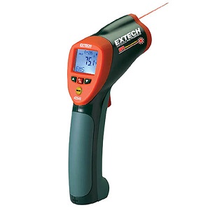
infrared thermometers are a very useful tool to track down issues with tuning, or mal functioning sensors
infrared thermometers are a very useful tool to track down issues with tuning, or mal functioning sensors , without verified facts your guessing.
this is the most consistently accurate I.R temp gun I've used for testing[/img]
http://www.testequipmentdepot.com/e...1100200223789&utm_content=All Extech Products
INFRARED TEMP GUN
Wide temperature range from -58 to 1832°F (-50 to 1000°C)
any time that your dealing with a potential temperature issue or a trouble issue where , knowing the exact temperature vs what a gauge might say, it helps to have a handy and accurate infrared temp gun handy to locate and confirm heat, levels.
http://forum.grumpysperformance.com/viewtopic.php?f=50&t=138&p=168&hilit=infrared#p168
partly clogged injectors tend to reduce power and increase emissions
if #6 headers running 100F higher than the rest of the cylinders on that cylinder head Id be looking for a vacuum leak on the intake or vacuum lines or a fuel distribution inconsistency issue, like a semi clogged injector or leaking fuel injector o-ring
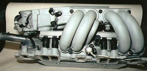
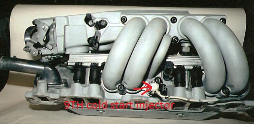
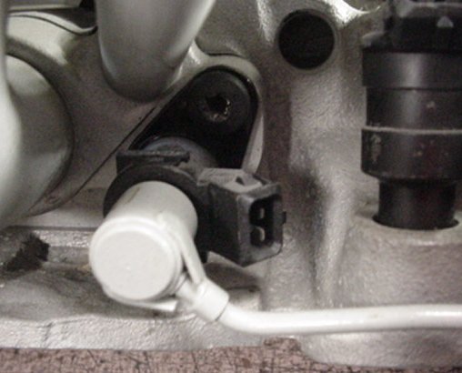
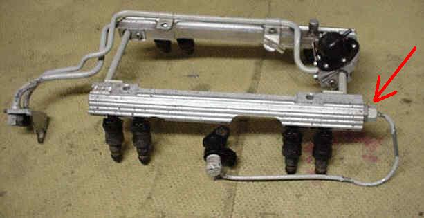
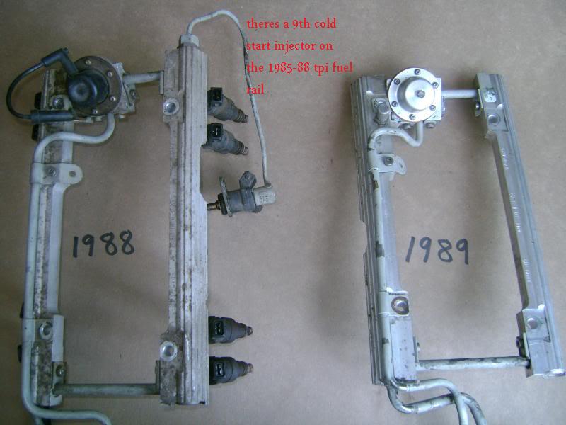
If youve got an early year TPI , thats designed to use a 9th cold start injector,check the cold start injector as its a potential problem source if its not working correctly.The cold start injector is between the front and rear pairs of runner tubes on the driver-side.on early TPI engines if its not working or loose causing a vacuum leak starting the engines much harder, later versions did not use these
one factor thats frequently over looked is the oil feed and return line internal size and line heat rating,THINK IT THRU, now it should be obvious that fittings tend to have smaller more restrictive holes thru them than the hose internal dimensions of the fittings used with that hose, a fitting designed for 3/8" hose wont allow full 3/8"hose or component oil flow rates, AN-6 is normally considered about equal to 3/8" but thats doesn,t tend to be true, AN-8 size fittings are usually used to get decent flow in a 3/8" oil cooler , if your oil cooler has 3/8" internal passages youll want an AN#8 line size too insure the MINIMUM 3/8" internal passage size is maintained , and you really NEED a full 1/2" or AN#10 size fittings and internal fluid transmission cooler lines to a fan cooled trans fluid cooler rated at at least a 24000 lb vehicle weight for race /performance use, and not restricted by use of the internal passage size of AN#6 fittings which are at best minimal and only delay the heat build-up related problems.
http://www.summitracing.com/parts/prm-13182
I don,t remember, where I purchased most of the oil/trans fluid coolers Ive used ,
but I've purchased and installed several oil and trans fluid coolers
over the decades, almost all were used 1/2" or an#8 connections and were purchased from summit or jegs
as always read carefully,
and measure accurately, remembering you must be leaving room for the hot oil or trans fluid hose and connections
and access to get the cooler in and mounted and connections made too it!
you would certainly not be the first or last guy to buy a cooler that will not fit in the space you though it would,
due to the connections and hoses required or forgetting about the thickness or lack of easy access.
https://www.summitracing.com/parts/der-15820
https://www.summitracing.com/search?PageSize=100&SortBy=BestKeywordMatch&SortOrder=Ascending&keyword=oil cooler with fan
https://www.jegs.com/i/Derale/259/15850/10002/-1
https://www.jegs.com/webapp/wcs/sto...&submodel=&engine=&Nrpp=&No=&persistYmm=false
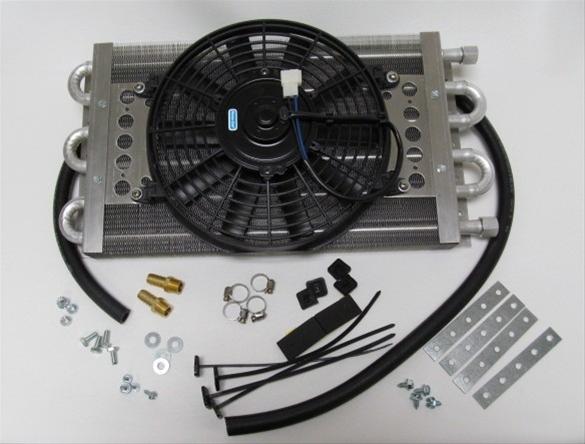
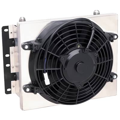
If I did it again Id select this trans cooler (pictured below) as the larger line size would help reduce flow restriction, its smaller width would make it easier to install,
THATS IMPORTANT!, MEASURE VERY CAREFULLY BEFORE ORDERING
I know several people that ordered trans coolers and found they would not fit into the originally intended location because they failed to correctly measure the intended location space, in ALL three dimensions,and over the whole space, before ordering , I know I failed to measure carefully so I was forced to place it where the spare tires normally mounted
http://www.summitracing.com/parts/FLD-DB30901/?rtype=10
Fluidyne High Performance DB30901 - Fluidyne Oil Cooler with Fan Kits
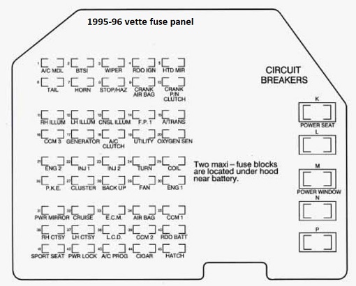
Chevrolet Corvette (1995 – 1996) – fuse box diagram
Year of production: 1995, 1996
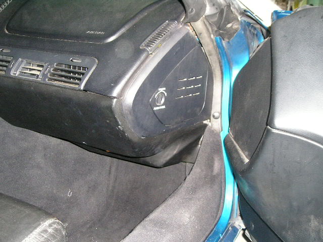
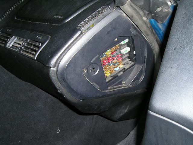
Instrument panel fuse block
The interior fuse center is on the right side of your instrument panel. Turn the knob and pull the door to access the fuses.
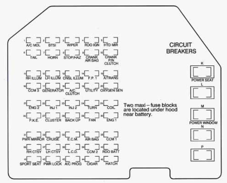
Chevrolet Corvette – fuse box – instrument panel
Fuses Usage
1 Heater, A/C Programmer
2 Brake-Transmission Shift Interlock
3 Windshield WiperNasher Switch Assembly
4 Radio Receiver (Ignition)
5 Heated Mirrors, Heater and A/C Control Head, Heater and A/C Programmer
6 Light Switch, Daytime Running Lamps Module
7 Horn Relay
8 Hazard Flashers, Brake Switch
9 Crank-Air Bag
10 Crank-Park/Neutral Switch (Automatic), Clutch Switch (Manual)
11 RH Illumination
12 LH Illumination
13 Console Illumination
14 Fuel Pump 1
15 Automatic Transmission
16 Central Control Module, Daytime Running Lamps Module
17 Generator
18 A/C .Compressor Clutch, Heater and A/C Control Head, Heater and A/C Programmer, Rev Defog Relay
19 Accessory Plug
20 Heated Oxygen Sensors
21 Real Time Damping Module, ABS Module, HVAC Solenoid Assembly
22 Injectors #1,4,6,7
23 Injectors #2,3,5, 8
24 Turn Signal Flashers
25 Ignition Coil and Ignition Coil Module
26 Passive Keyless Entry Module
27 Instrument Cluster, Driver Information Center, Air Bag System
28 Back-up Lamps Switch, Transmission Position Switch, One to Four Shift Solenoid
29 Cooling Fan Relay Coil #1 , 2,3
30 Canister Purge Solenoid, EGR Circuit (LTl), Mass Airflow Sensor, One to Four Shift Relay, Brake Switch (Automatic), Air Pump Relay
31 Power Mirror Adjuster Control, Lighted Rearview Mirror, Visor Vanity Mirrors
32 Cruise Control Engage Switch, Daytime Running Lamps Module, Low Tire Pressure Warning Module, Cruise Control Cut-off Relay
33 Engine Control Module
34 Air Bag System
35 Central Control Module
36 Footwell Courtesy Lamps, Door Courtesy Lamps, Glove Compartment Lamps, Lighted Rearview Mirror
37 Bose Amplifier Relay, Power Antenna Relay, Cargo Compartment Lamps
38 Instrument Cluster, Tone Generator, Dome Lamp Relay
39 Central Control Module
40 Radio Receiver (Battery), Radio Control Head, Passive Keyless Entry Module
41 Sport Seats
42 Power Door Lock Switches, Driver Information Center, Passive Keyless Entry Module
43 Heater and A/C Programme
44 Cigarette Lighter, Accessory Plug
45 Hatch or Deck Lid Release Relay
K Power Seats
L Blank
M Power Window
N Blank
P Blank
Engine compartment fuse block
There are two maxi-fuse blocks in the engine compartment. One is part of the forward lamp wiring harness and the other is part of the ECM-engine wiring harness.
Forward Lamp Fuse Block
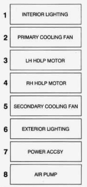
Chevrolet Corvette – fuse box – forward lamp fuse block
Fuse Usage
1 Interior Lighting
2 Primary Cooling Fan
3 LH Headlamp Motor
4 RH Headlamp Motor
5 Secondary Cooling Fan
6 Exterior Lighting
7 Power Accessory (Power Locks, Hatch, Lighter, Seats)
8 Air Pump
ECM Engine Fuse Block
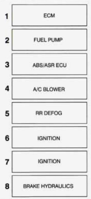
Chevrolet Corvette – fuse box – ECM engine fuse block
Fuse Usage
1 Engine Control Module
2 Fuel Pump
3 Anti-Lock Brakes, Acceleration Slip Regulation System
4 A/C Blower
5 Rear Defogger
6 Ignition
7 Ignition
8 Brake Hydraulics
WARNING: Terminal and harness assignments for individual connectors will vary depending on vehicle equipment level, model, and market.
1996 radiator cooling fan relay how to test
Hello all, I have a 1996 Vette LT-4, radiator cooling fans are not coming on. I have checked the fuse panel on the passenger side of the dash, I have also checked the maxi fuses in front on the battery. am now desirous of checking the cooling fan relays, how to do this? thanks in advance for any/all guidance
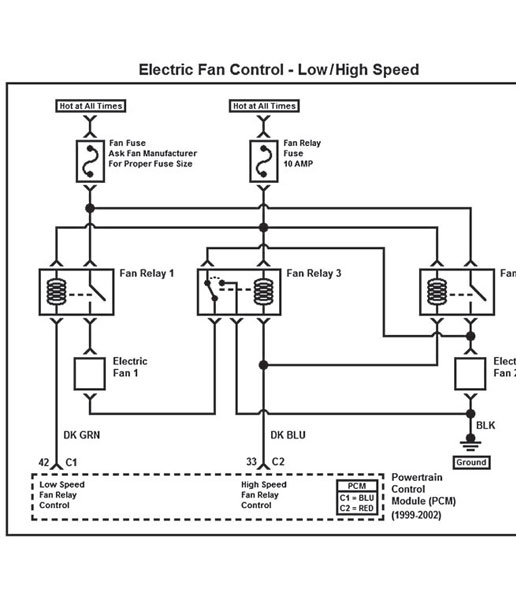
There are three relays involved.
You can identify the relays by the color of the wires at each relay socket.
Turn the ignition On.
At the relay socket.
Ground the Dark Green wire and both fans should run at low speed.
Ground both the Dark green wire and the Dark Blue wire and both fans should run at hi speed.
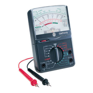
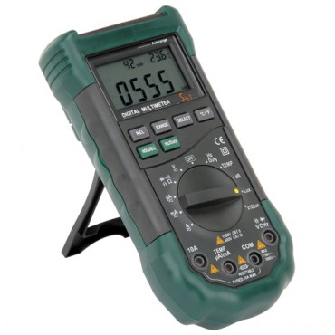
every mechanic needs an ANALOG multi meter for testing capacitors with a micro farad scale, AND a DIGITAL MULTI METER
http://forum.grumpysperformance.com/viewtopic.php?f=36&t=63&p=3403&hilit=vats#p3403
use of a shop manual and multi meter can be very helpful
http://www.harborfreight.com/5-in-1-digital-multimeter-98674.html
READ THIS THREAD
http://forum.grumpysperformance.com/viewtopic.php?f=32&t=3954
READ THESE LINKS AND SUB LINKS
http://garage.grumpysperformance.com/index.php?threads/cooling-off-that-c4-corvette.3954/
http://garage.grumpysperformance.co...-air-conditioner-on-cooling.12232/#post-59597
http://garage.grumpysperformance.co...sion-and-oil-cooler-increases-durability.176/
http://garage.grumpysperformance.co...ans-cooler-on-a-c4-corvette.10514/#post-44478
http://garage.grumpysperformance.com/index.php?threads/i-need-a-new-lt1-water-pump.10723/
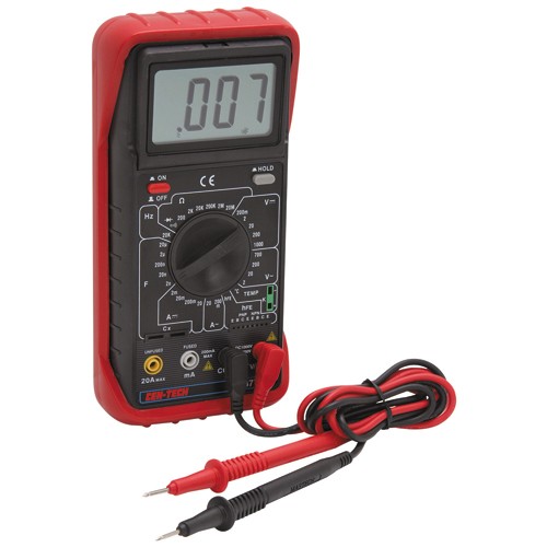
you really need to purchase a multi meter and a SHOP MANUAL and look thru the schematics
without testing theres almost no way to locate the source of your problem,, testing will tell you
http://www.helminc.com/helm
http://www.harborfreight.com/5-in-1-dig ... 98674.html
heres a cheap yet effective multi meter
http://garage.grumpysperformance.co...sing-a-crazy-electrical-glitch.986/#post-1738
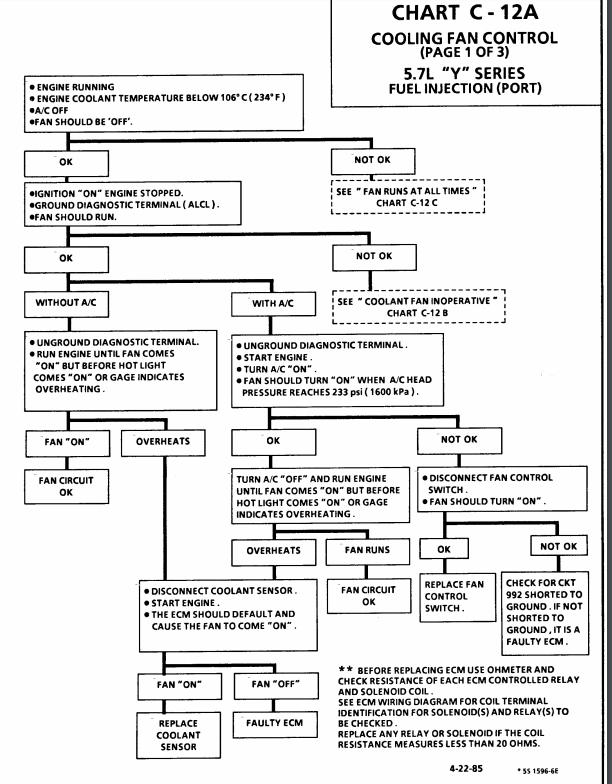
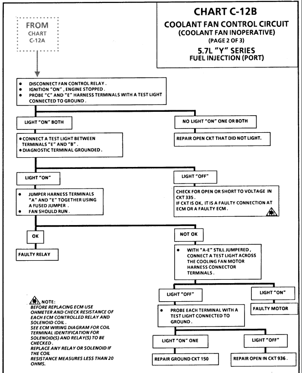
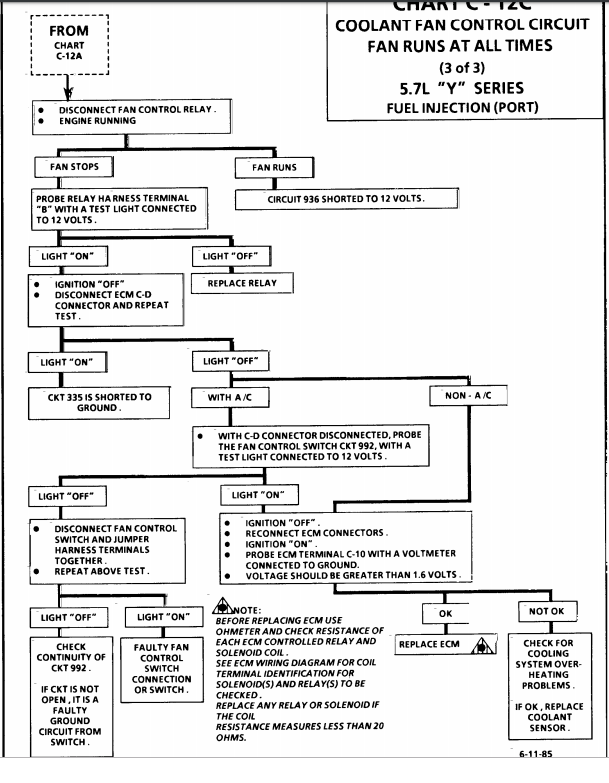
these charts are for the 1985-89 vette cooling fans

# Check fan fuses in the underhood fuse/relay panel
# Check fan relays (same location). Aside from getting out any electrical equipment to test the relay, you can swap it with another one (such as the fog lamp relay) and test for function. See if the relay works for the fog lamps and/or the swapped-in relay makes your fans work. Nearly all the relays in the panel are the same, except for maybe the ABS relay.
# You can jumper two pins on the DLC that should cause the fans to come on. 1993-1994 cars with the 12 pin DLC can jumper pins A and B. On a 1993, that is the same way that you would retrieve trouble codes from the ecm. The 1994 won't give you any codes, but the fans will engage. 1995-1997 uses pins 5 and 6 on the 16 pin DLC to initiate what is called "field service enable mode". That will cause the fans to come on and operate most sensors for sanity checking. After placing the jumper on the correct pins, turn the key to ON (don't start). If the fans work after jumpering the DLC, your PCM is capable of operating the fans and all fan wiring/relays should be ok.
# Deeper problems can be solved through testing and using the wiring schematic.
~Fans don't come on except when the a/c or SES is on~
~Temp gauge continues to rise with no automatic fan operation~
# With a scan tool, check to see what temp the PCM is seeing from the sensor in the water pump. Make sure you are aware of the temps the fans come on (stated in the beginning of this article). If the temp it sees is incorrectly low, it won't know to turn the fans on. Another possibility is that the temp is really ok, but the gauge is reading wrong. That is why you need to use the scan tool to see and compare the readings. Info on testing wiring and sensor can be found here.
# If that looks ok, then your PCM may have issues. You could always try resetting the PCM by pulling the PCM BAT fuse for about 30 seconds.
viewtopic.php?f=70&t=3504&p=9220#p9220
Testing the ECT (Engine Temperature) Sensors and Connections
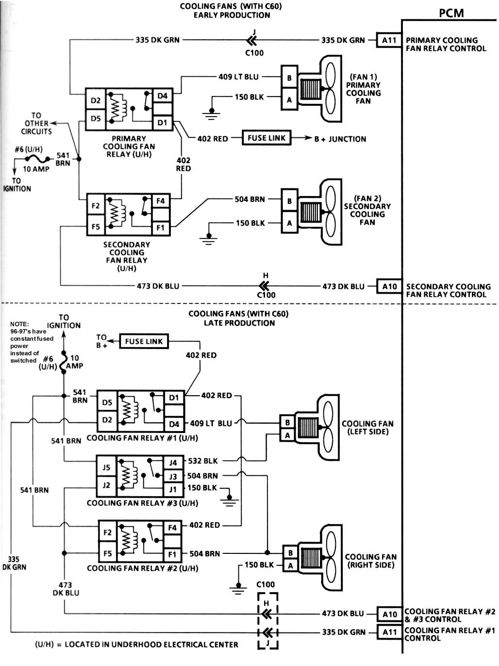
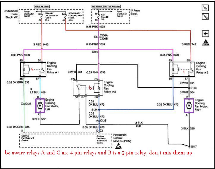
THE DIAGRAM ABOVE HAS THE CORRECT WIRE COLORS

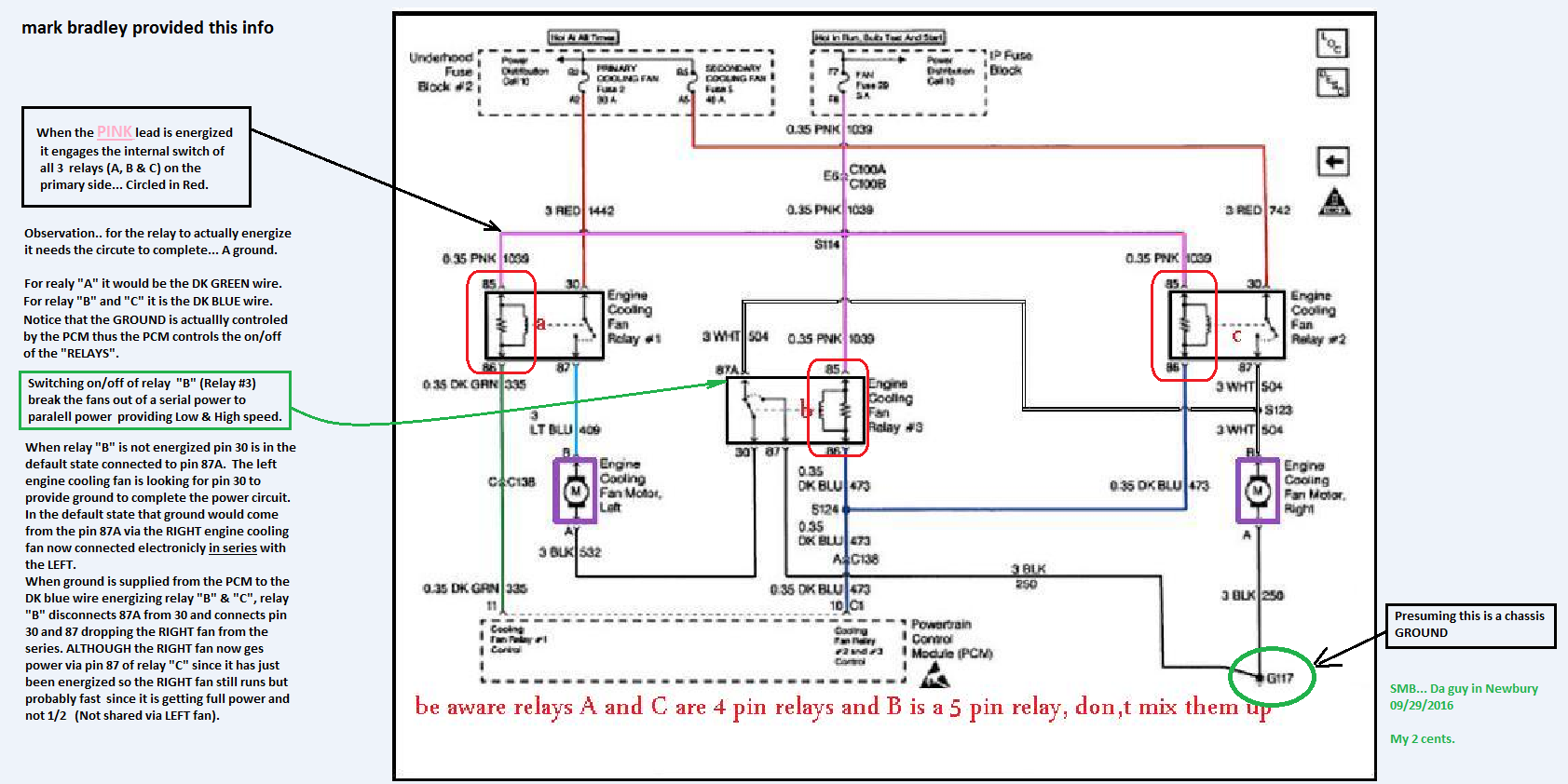
Pro tip before starting - Label your relays Relay 1, Relay 2, and Relay 3 according to the wiring diagram (your first post) and what your physical relays represent. Even if its just a sticky note. Get it all straight and stick to the same annotation while you troubleshoot.
You'll need a multimeter than can measure DC voltage and continuity:
Remove all three relays so you're only dealing with the sockets
DC Voltage tests:
1. Confirm 12V between the socket for pin 85 and the negative battery terminal on all 3 relay sockets
2. Confirm 12v between the socket for pin 30 and the negative battery terminal on relay sockets 1 and 2
Continuity tests:
1. Confirm continuity with the end of the dark green wire and the socket for pin 86 for relay 1
2. Confirm continuity with the end of the dark blue wire and the socket for pin 86 for relay 2 AND relay 3.
3. Confirm continuity between the socket for pin 87 for relay 1 and side B of the left cooling fan connector
4. Confirm continuity between side A of the left cooling fan connector and side B of the right cooling fanconnector AND the socket for pin 87 for relay #2.
5. Confirm continuity between the socket for pin 87 for relay #3 and Negative Battery Terminal
6. Confirm continuity between side A of the right cooling connector and Negative Battery Terminal.
Do the steps in order and use the negative battery terminal for your connection when I specify to. Verifying at the negative battery terminal will ensure you're circuit is making a good connection to the chassis ground. If it doesn't make it all the way back to the battery, it's a crap ground and testing it my way will reveal the problem
ECT Temperature vs. Resistance Values
ºC ºF Ohms
100 212 177
90 194 241
80 176 332
70 158 467
60 140 667
50 122 973
45 113 1188
40 104 1459
35 95 1802
30 86 2238
25 77 2796
20 68 3520
15 59 4450
10 50 5670
5 41 7280
0 32 9420
-5 23 12300
-10 14 16180
-15 5 21450
-20 -4 28680
-30 -22 52700
-40 -40 100700
Use a Digital Volt Meter (DVM) set to ohms to measure resistance. Note: Use a high impedance meter (at least 10 megohm) when dealing with the PCM. Most modern DVMs will do, but your old analog meter can damage the PCM. It is also a good idea to get a " reference" from the meter you are working with. With the DVM on the ohms scale, touch the two meter leads together and note the ohm reading. It may not always be perfectly zero, but may be within a tenth or two. Now when you take an ohm reading, you will know what the meter will show when there is really no resistance.
* The sensor in the head has only one terminal. This sensor is for the temperature indicator on the dashboard. Place one test lead on the sensor terminal and the other on a known good ground. Compare the reading to the table. If your car is cold from sitting overnight, the reading should be close to ambient temperature.
* The sensor in the water pump has two terminals. This sensor is for the temperature input to the PCM. Place a test lead on each of the sensor terminals to take the reading. (When reading resistance, it does not matter which lead goes to which terminal)
If the sensor seems to be ok, you may also need to test at the harness connector for proper lead conditions. Use your test meter set on the dc voltage scale to do this. You will need the key in the RUN position, but don't have to start the car.
* For the one lead connector at the head, place the red test lead on the connector terminal and the black test lead to a known good ground. With the key ON, you should read battery voltage (+12vdc or close to it). You can also ground the lead and see if the gauge in the car deflects to full hot.
o If you get no voltage, switch the meter to ohms to see if the lead is grounded.
o No voltage or no ground mean that the lead is open.
o If the gauge is at full hot all the tme, the lead is grounded back toward the gauge. It could be possible for the lead to be pinched and grounded toward the gauge and broken and open back toward the sensor (like in the case of the wire getting caught somewhere during some major engine work). Physically tracing the wire from the sensor into the harness should locate the problem.
* The two lead connector at the water pump has a black (ground) lead and a PCM +5vdc power lead (probably yellow). Place the black meter test lead to black connector lead and the red meter test lead to the other connector lead (yellow on my 1995). You should read +5vdc because this is monitoring voltage being supplied from the PCM.
* If you get no reading:
o Test the yellow lead by placing the DVM red lead on it and the DVM black lead to ground. A +5vdc reading will indicate the lead is ok.
+ If you get no voltage, switch the meter to ohms to see if the lead is grounded.
+ No voltage or no ground mean that the lead is open.
o You can test the black connector lead by using the ohms scale on the DVM. Place the DVM black lead to ground. Place the DVM red lead to the black lead of the connector. If the lead is ok, you will get an ohm reading close to zero. If you get no reading or a very high one, the lead is open or partially open.
* OBD-I DTCs 14 and 15 or OBD-II DTCs P0117 and P0118 are typically associated with problems the PCM sees with the sensors or circuits.
Footnote: If you ever have to test the IAT, it operates the same as the two lead coolant sensor. The same temp vs. resistance table above is applicable to the IAT, as well as the +5vdc lead and ground wire at the harness connector.
related threads
http://garage.grumpysperformance.com/index.php?threads/c4-c5-corvette-trouble-codes.2697/#post-69239
http://garage.grumpysperformance.com/index.php?threads/locating-vacume-leaks.882/#post-45944
http://garage.grumpysperformance.co...lay-switch-locations-and-info.728/#post-54562
http://garage.grumpysperformance.com/index.php?threads/c3-c4-corvette-vacuum-diagrams.1773/
http://garage.grumpysperformance.co...leaning-trash-out-of-the-radiator-fins.11712/
http://garage.grumpysperformance.com/index.php?threads/head-scratcher-cooling-issue.3010/#post-84329
http://garage.grumpysperformance.co...fo-and-derale-trans-cool-pans.662/#post-34937
http://garage.grumpysperformance.com/index.php?threads/that-c4-corvette-cooling-fans-issue.16049/
http://garage.grumpysperformance.com/index.php?threads/cooling-off-that-c4-corvette.3954/
http://garage.grumpysperformance.com/index.php?threads/sources-for-tpi-parts-and-info.590/#post-1074
http://www.superchevy.com/how-to/15044-1991-chevrolet-corvette-oil-cooler-maintenance/
http://garage.grumpysperformance.co...ans-cooler-on-a-c4-corvette.10514/#post-44498
Last edited: