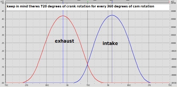
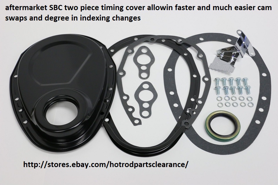
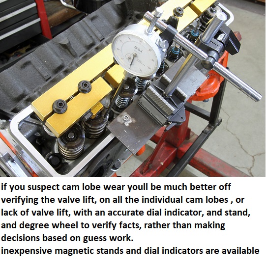
IM frequently asked (why bother degreeing in a cam, the timing set comes with index marks to install it?)
it basically comes down to, a question of do you accept a random install where the timing can be almost any place randomly or do you insist on maximizing the engines potential and know exactly how and why things work.
when your degreeing in a cam your verifying that the cam card figures , you purchased the cam for MATCH what the cams going to be doing in the engine , if everything is correct a dot-to-dot install will be almost identical, but the fact is that due to manufacturing tolerances a dot-to-dot install will frequently be a few degrees off!
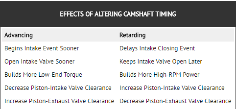
almost EVERY manufacturer grinds their cams 4 degrees advanced if installed with the dot-to-dot install method, this is almost standard practice, it was and is done to marginally boost the cams lower to mid range torque, now most guys might never notice, but it can and frequently does effects the engines power band so getting it correct helps and eliminates one potential source of problems (be damn sure you verify the cams degreed in correctly and the ignition firing orders correct and all the distributor wires go to the correct cylinder,s spark plugs and distributor cap locations)
ITS also a great way to catch mistakes before you get to the point where you try to start the engine with the cam indexed incorrectly, if you used the wrong index marks on the timing set..
WELL,theres manufacturing tolerances in all machined components , in most case the tolerances are rather random to some degree and tend to cancel out the differences between the components to some degree, and the AVERAGE result is that most of the time if your, cams a few degrees off, the ideal location most people will never know it and that's fine, but occasionally the tolerances stack up to cause a problem, or clearance issues.
you can easily find a few degrees of cam timing difference can cause or cure detonation problems or (PINGING) under loads, and in a few cases piston to valve clearance is critical, once you get into building performance engines you'll also find that the intake and exhaust are ideally tuned for a set power band and having the cam a few degrees off from the ideal will cost you some power.
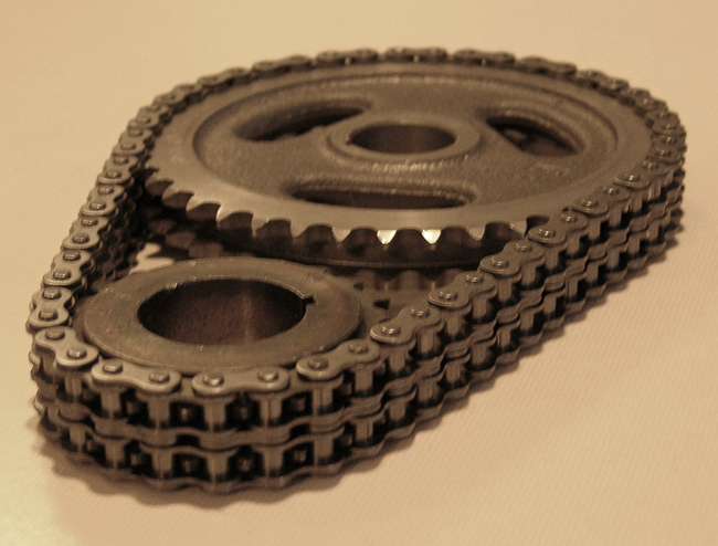
you can install most cams with the common (DOT-TO-DOT) timing set marks if you use quality components like CLOYES timing sets and name brand cams but even then theres variations that youll see once you degree in the cam rather than assume its correctly indexed
and using the dot-to-dot route youll be within about 2-3 degrees in most cases, which is close enough to get the car to run decent, but a 4 degree change results in about a 200rpm change in the cars power band RPM range, the tolerances can result in a 3-7 degree off set with the cheap import timing sets and cheaper mass produced cams, in most cases you'll never notice, but if the cars set up to run with close tolerances, high compression and ideal quench ETC. that could easily result in 10-20hp, IVE seen some cases where the difference was quite noticeable, in the way the car ran, and a few cases where cheap import timing sets were WAY OFF and would have cost you a good deal of hp/tq at least and probably caused clearance issues, or over heating or a noticeable power loss if installed without checking.
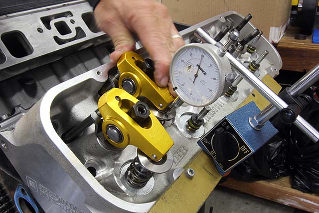
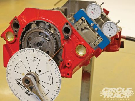
theres also more to it than just INDEXING the cam, you need to set up the valve train geometry and check spring rates and clearances carefully, and indexing the cam timing in the engine in relation to the piston location, during its rotation can be a valuable tuning aid , as you can easily degree in a cam so its 4-6 degrees advanced or retarded from the split overlap or strait up location, easily tuning the power band up to about 200-250 rpm either direction in the rpm band, changing the opening and closing points in the cam timing, effects the DCR and the power band, but its also useful in getting the intake and exhaust tuned but past those limits swapping to a different cam is almost always the better choice
BTW I assume you gentlemen do know theres
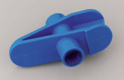
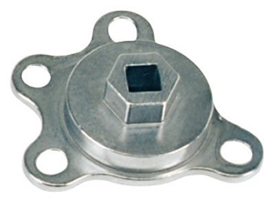
even a correct and very inexpensive tool for spinning it from the flex-plate or flywheel,
once the cylinder heads are installed,
so your not stressing the damper retention bolt spinning the engine over manually, If you need to verify TDC and your cylinder heads are still on,
it's done all the time, read these threads linked below carefully
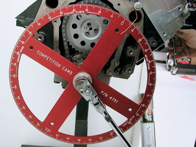
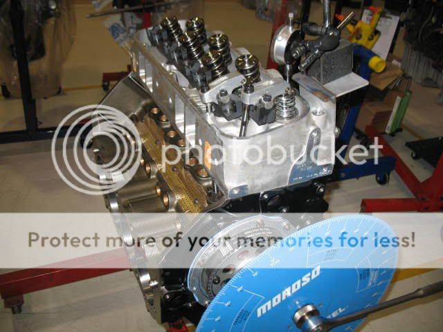
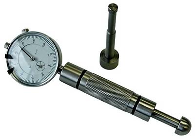
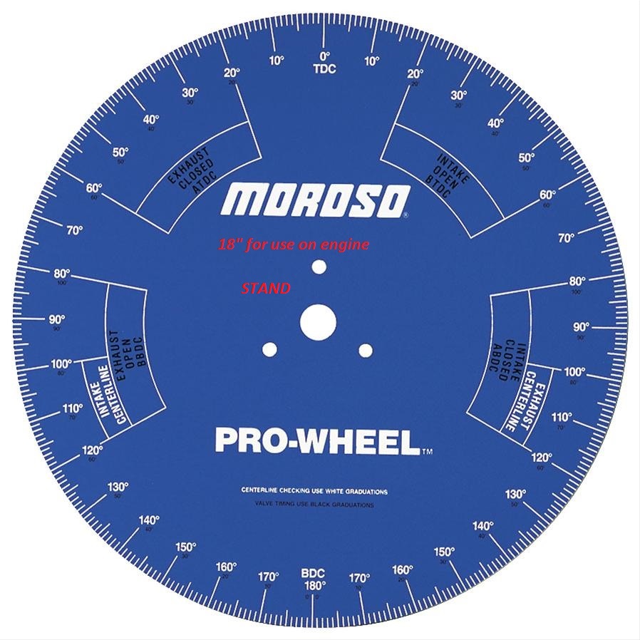
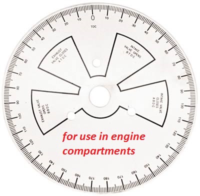
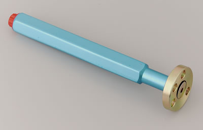
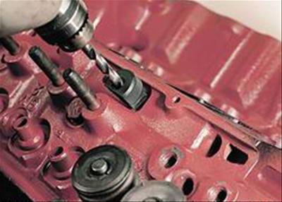
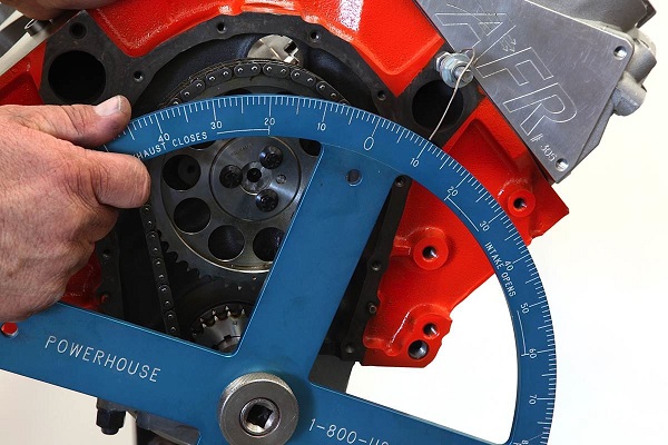
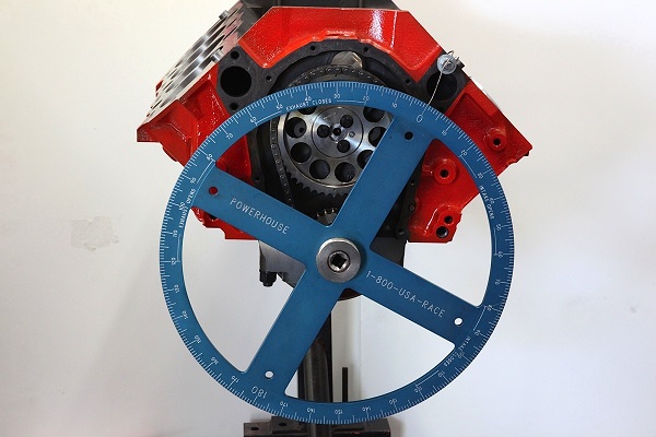
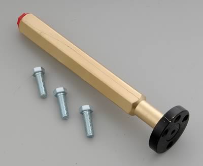
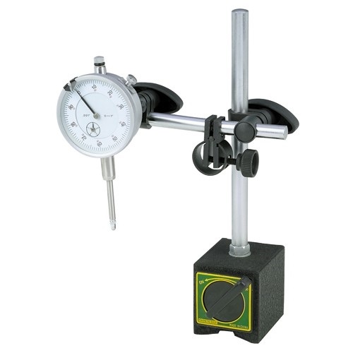
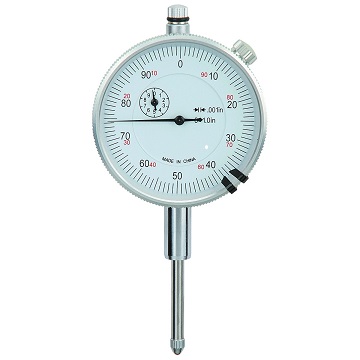
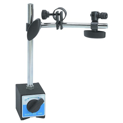
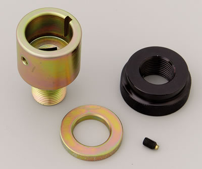
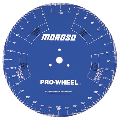
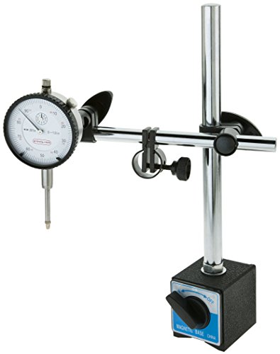
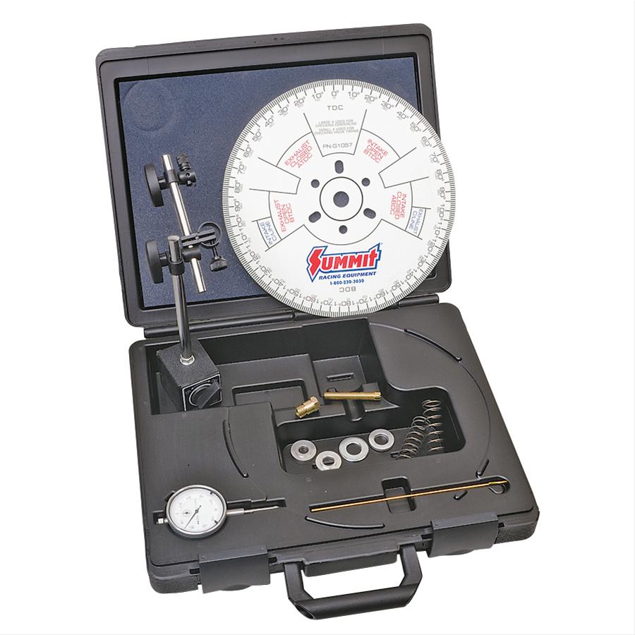
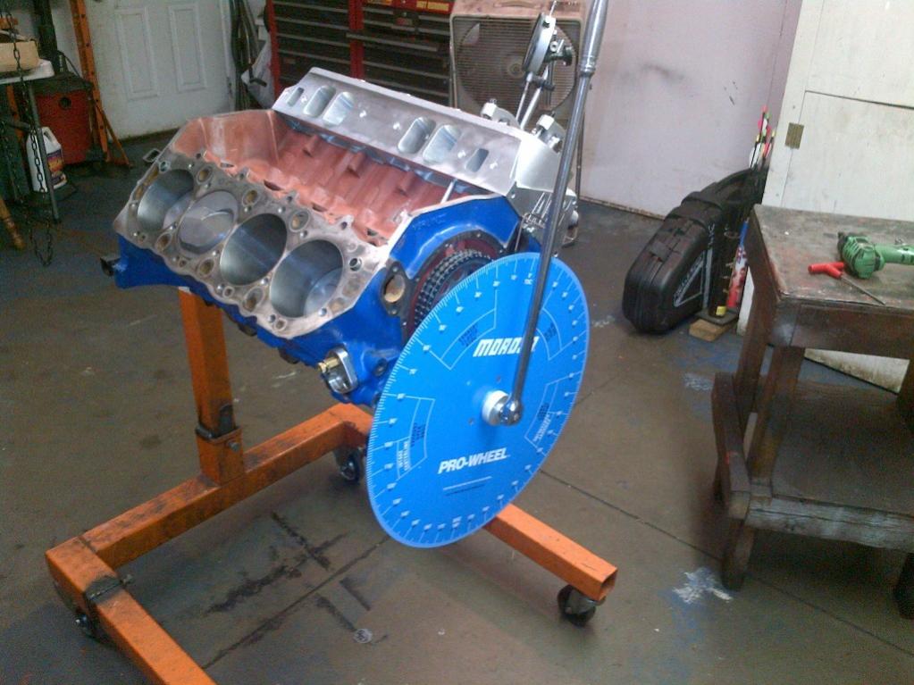
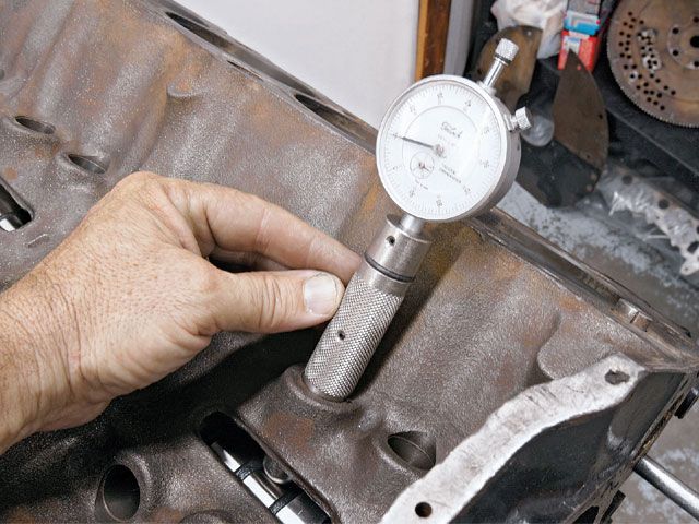
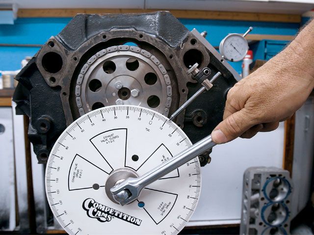
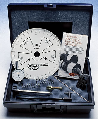
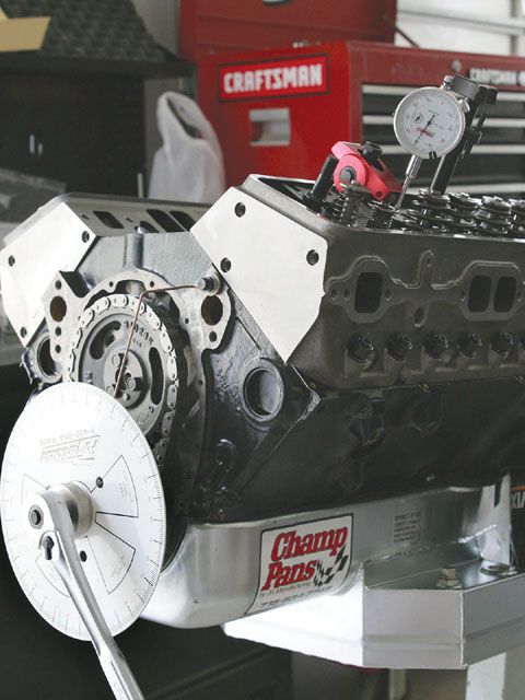
you need a degree wheel, that bolts to the crank snout
Use of a crank snout adapter and removing the damper is prefered but not required
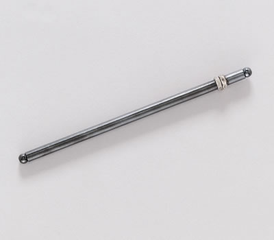
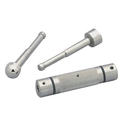
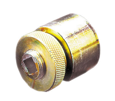
and a piston stop that screws in where the spark plug normally goes
http://garage.grumpysperformance.co...ng-cam-and-shifting-the-lca.10553/#post-44949
http://garage.grumpysperformance.co...op-dead-center-1-for-timing-ignition-cam.966/
http://garage.grumpysperformance.com/index.php?threads/turning-your-crank-manually.5933/

https://www.summitracing.com/parts/wmr-w80510/overview/
https://www.summitracing.com/parts/sum-900178/overview/
http://www.cranecams.com/bulletins_listview.php?s_id=7
most manufacturers IDENTIFY OR mark cams under the timing gear mount surface
READING THRU the linked info below will help,a great deal, and yes IM well aware theres a ton of info posted in the links, reading and understanding that info will be to your benefit, well beyond the time it takes you to read thru it, and it can easily save you many hours and avoid costly repairs by doing the reading before you need to do repairs, due to over-looked steps or incorrectly installed parts

 www.youtube.com
 www.youtube.com
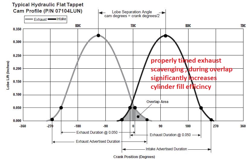
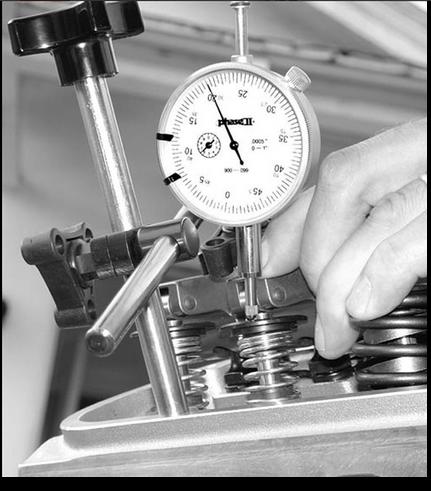
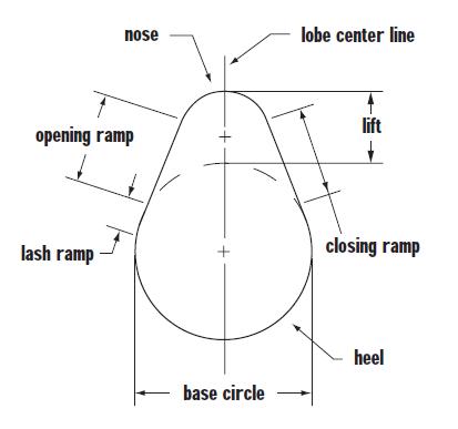
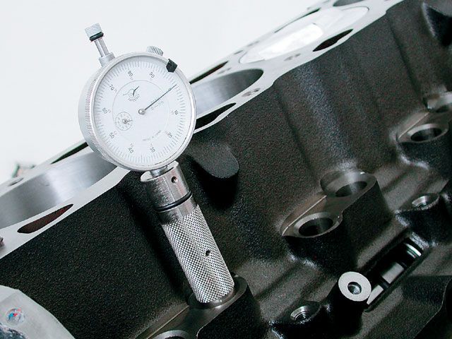
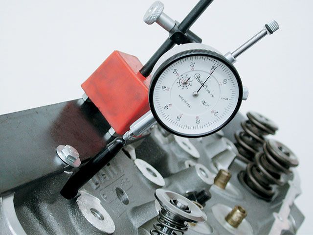
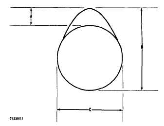
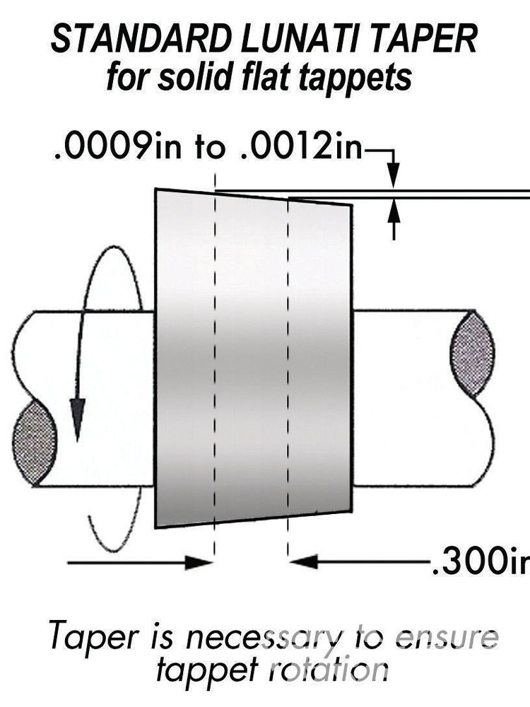
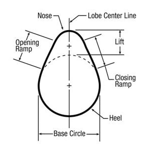
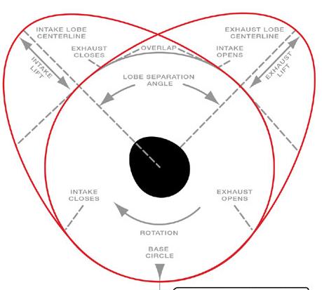
A non-symmetrical lobe will have a different center-line when
checked at 0.050†above the base circle than it does when checked at 0.050†from either side of the top of the lobe.
camshafts should always be checked at the bottom of the lobe, which is 0.050†tappet lift off the base circle.
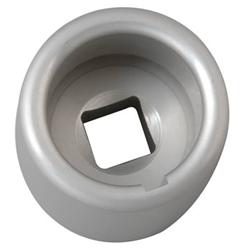
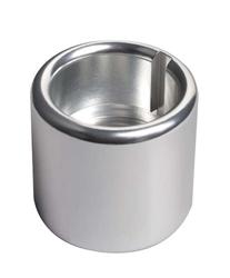
Proform Parts 66830 - Proform Cam Checking Fixture Kits


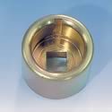
THE PROFORM SOCKETS ARE ALUMINUM
http://www.summitracing.com/parts/PRO-67492/
http://garage.grumpysperformance.co...op-dead-center-1-for-timing-ignition-cam.966/
http://www.summitracing.com/parts/PRO-67491/
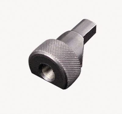
if your wondering how to turn a crank over to do test and diagnosing and cam installs you will benefit from the proper tools
IF you remove the spark plugs and take the car out of gear its fairly safe to turn the engine over manually,
using a breaker bar on the cranks damper retainer bolt,the problem is 99.9% of us are LAZY,
and just try it as the engine sits and eventually we strip the crank bolt or the crank snout threads
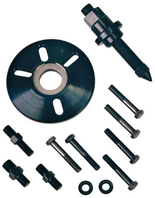
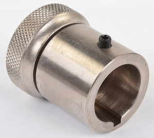
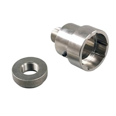
If the damper been removed the crank snout socket thats designed for your crank to turn the crank.
and hold the degree wheel while degreeing in the cam will be the route to take
shop carefully and ask questions the sockets and tools don,t fit universally, you'll need an assortment of several OF EACH TYPE ONCE YOU GET INTO ENGINE BUILDING SERIOUSLY
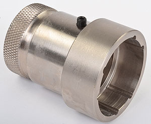
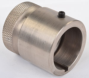
the crank socket like this that can turn the crank safely and firmly and accurately mount a degree wheel is prefered
there are also crank turning nuts that fit individual crank sizes
most of us are too lazy to remove the damper/balancers
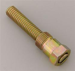
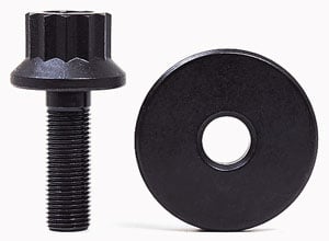
there are over size extra strength damper bolts for sale that are less likely to strip
they sell an engine damper bolt on tool that fits some dampers that allows you to use a 1/2" breaker bar rather easily
http://www.summitracing.com/parts/pro-66782?seid=srese1&gclid=CNqD0YXA48gCFUYYHwodBJ4DVA

IT MAKES LITTLE SENSE TO BUY the sockets that don.t have the provision for mounting the cam degree wheel to save a few dollars in my opinion
when purchasing a crank socket try to find one designed to easily accept and lock down a degree wheel
THE COMP SOCKETS ARE FAR MORE DURABLE STEEL
http://www.jegs.com/i/COMP+Cams/249/4914/10002/-1 LS ENGINES
http://www.jegs.com/i/COMP-Cams/249/479 ... ProductId= BBC ENGINES
http://www.jegs.com/i/COMP-Cams/249/479 ... ProductId= SBC ENGINES
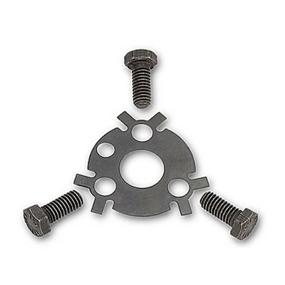
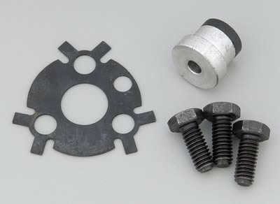
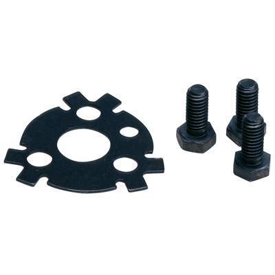
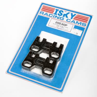
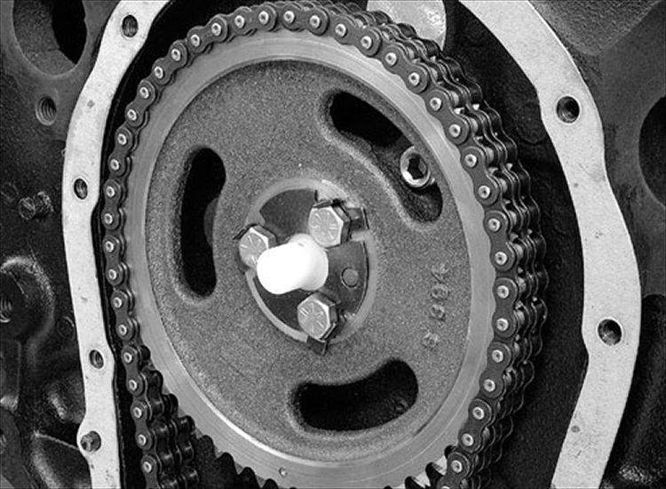
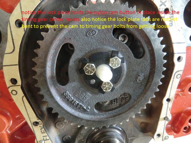
a properly installed nylon cam button with a bolt retainer plates a good idea
youll generally use LOC-TITE on the retainer bolts threads
youll generally use LOC-TITE on the retainer bolts threads
use loc-tight on the bolt threads to reduce any tendency for them coming loose

a properly installed nylon cam button with a bolt retainer plates a good idea
http://www.tavia.com/free_degree_wheel.html
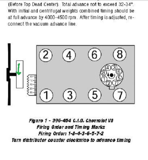
WHEN CRANK IS AT TWELVE AND CAM IS AT SIX THEN #6 CYL IS FIRING AFTER YOU LINE UP YOUR MARKS AND INSTALL GEAR THEN ROTATE YOUR CRANK ONE REVOLUTION AND THEN DROP THE DIST. IN - AT THAT POINT
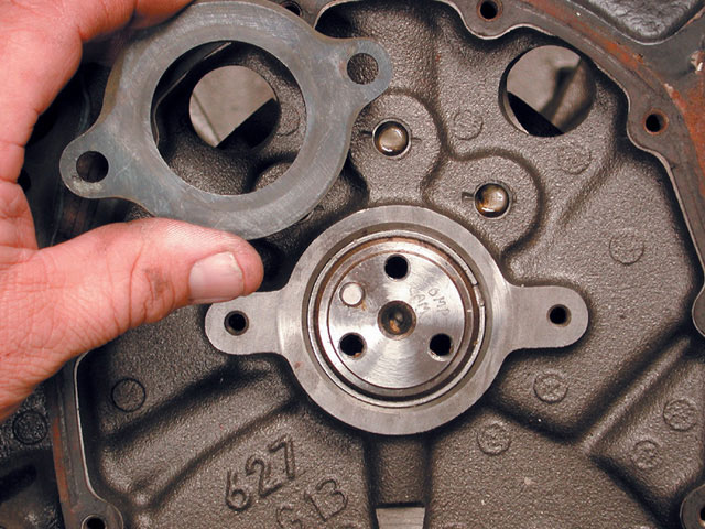
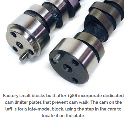
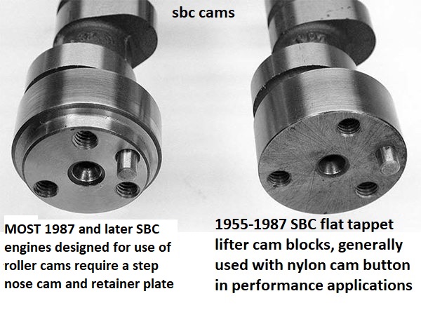
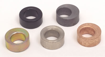
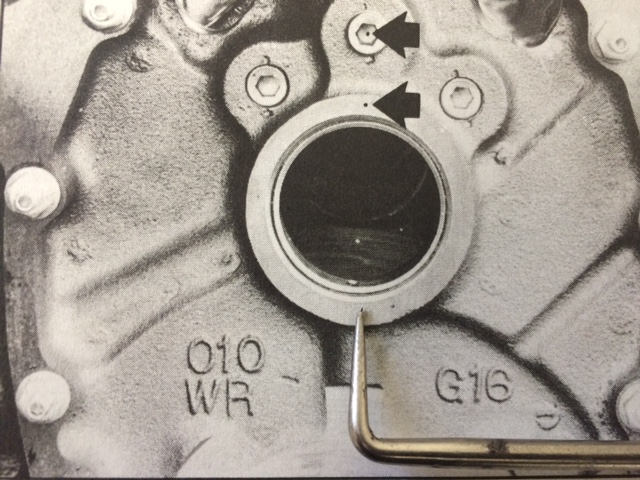
Starting in 1987 GM began using a hydraulic roller cam in their production car engines.
This required a cam thrust plate on the front of the block.
The step in the nose of this cam (left) identifies it as a cam intended for use in a production roller cam block.
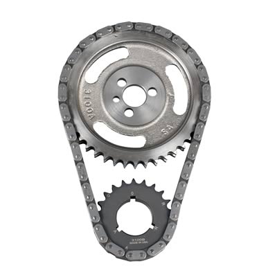
If your ever in doubt, about the correct timing chain application,
CALL THE TECH GUYS AT CLOYES
cloyes tech dept 1-479-646-1662 EXT 228
with the older style non-step nose cam, in the newer style "08" block, you will NOT use the retainer plate
you should use a cloyes 9-3100 timing chain, set
https://www.summitracing.com/parts/clo-9-3100
http://garage.grumpysperformance.com/index.php?threads/semi-fool-proof-cam-sellection.82/
http://garage.grumpysperformance.co...hanics-of-adv-ret-a-camshaft.4532/#post-12050
http://garage.grumpysperformance.com/index.php?threads/cam-drive-details.3809/#post-10226
http://garage.grumpysperformance.com/index.php?threads/wear-plate.3777/#post-10011
http://www.wallaceracing.com/cam-deg-calc.php
http://www.hughesengines.com/Upload/pro ... ar2010.pdf
http://69.20.53.62/pdf/803.pdf
http://www.iskycams.com/degreeing.html
http://garage.grumpysperformance.co...e-springs-and-setting-up-the-valve-train.181/
http://www.thedirtforum.com/degree.htm
http://www.lunatipower.com/Tech/Cams/Ho ... eACam.aspx
viewtopic.php?f=52&t=399&p=1689#p1689
http://www.streetsideauto.com/images/BB ... e/214e.pdf
http://garage.grumpysperformance.com/index.php?threads/chain-vs-gear-drive-cam.781/#post-72280
http://www.classicinlines.com/cam_degree.asp
http://www.lunatipower.com/Tech/Cams/CamSpecTerms.aspx
http://cranecams.com/?id=2&show=faq
http://www.jegs.com/InstallationInstruc ... 119661.pdf
http://www.aa1car.com/library/camshafts.htm
viewtopic.php?f=52&t=1070&p=2054#p2054
http://www.harborfreight.com/cpi/ctaf/d ... umber=5645
http://www.thirdgen.org/sbc-camshafts-primer
https://www.holley.com/data/Products/Te ... NST150.pdf
http://www.cam-shield.com/index.html
http://www.camshaftinnovations.com/FTT_ ... ingCam.htm
http://garage.grumpysperformance.com/index.php?threads/upgrade-choices.11416/
http://www.trishieldperf.com/cam_degreeing.htm
http://www.faliconcranks.com/pdf/degree ... mshaft.pdf
http://www.ls1howto.com/index.php?article=23
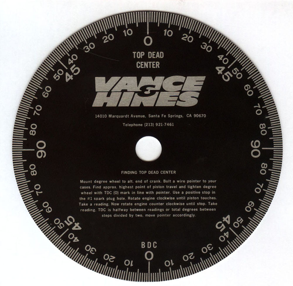
LINK TO INFO ON A printable degree wheel and related info
viewtopic.php?f=52&t=974
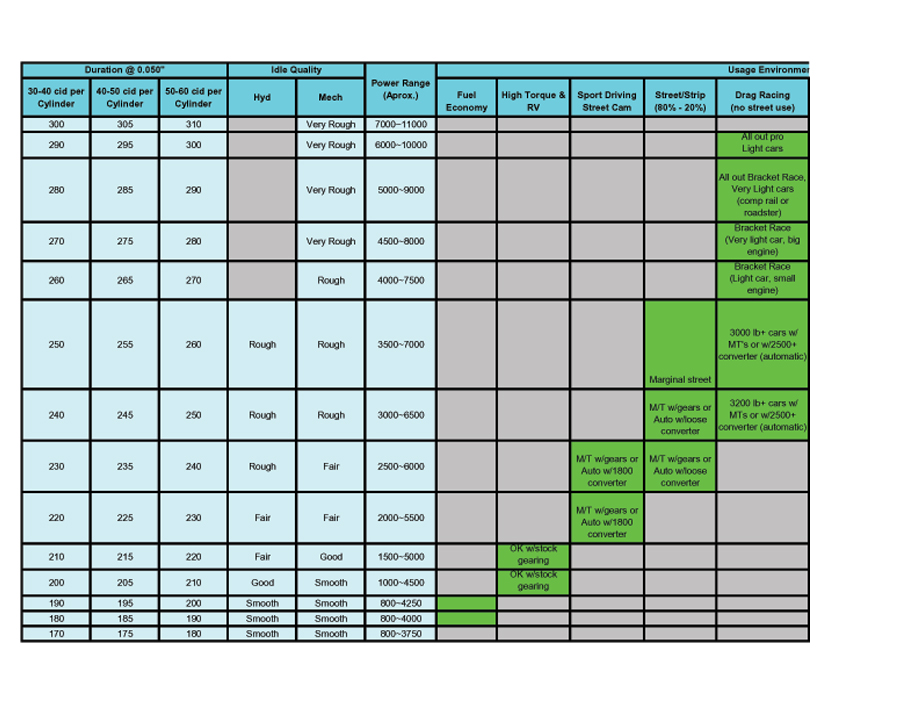
The following Mechanical operating clearances must always be verified to ensure proper operation of the camshaft:
Spring coil bind clearance
Retainer to seal/valve guide boss clearance
Piston to valve clearance
Rocker arm slot to stud clearance
Camshaft endplay
Distributor shaft and gear endplay
Connecting rod to cam clearance
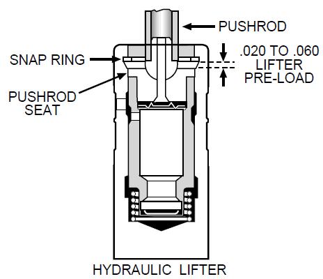
Proper hydraulic lifter pre-load or lash clearance
Proper valvetrain geometry
proper spring load rates
rocker to retainer clearance
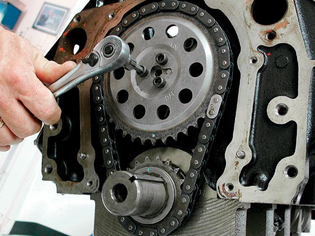
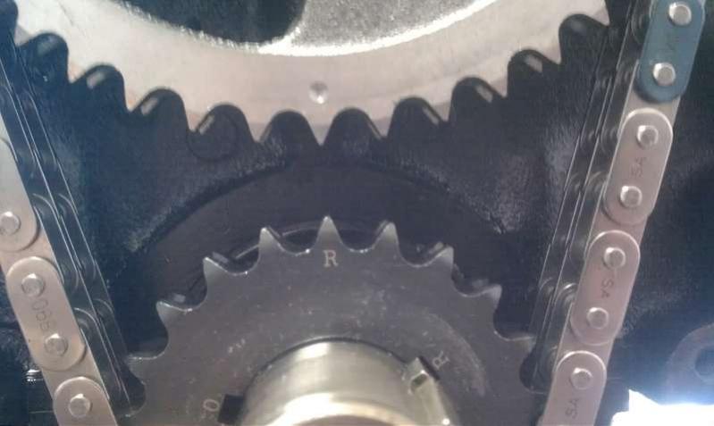
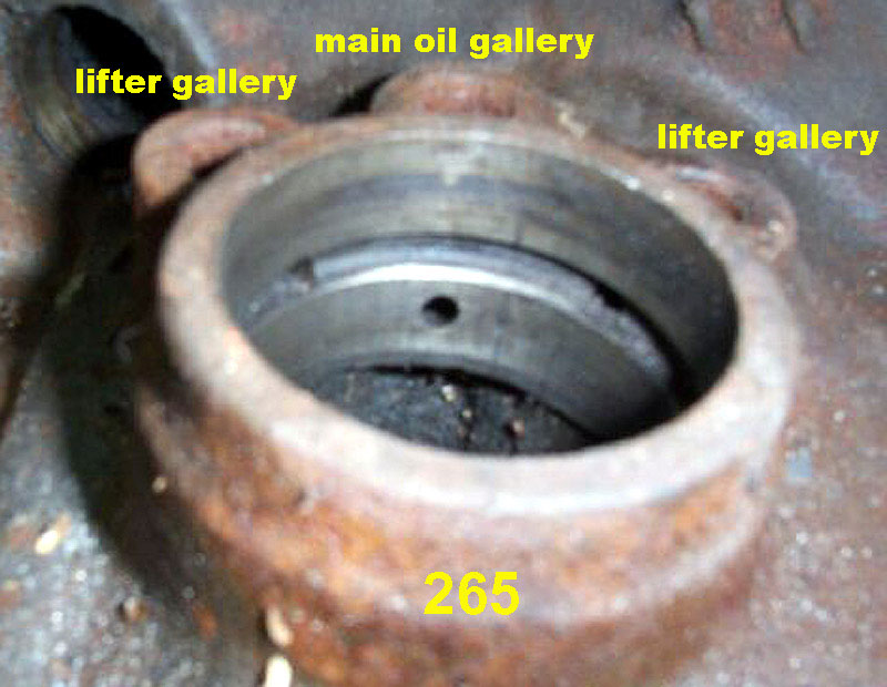
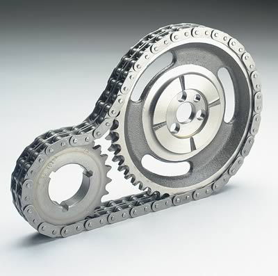
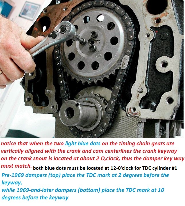
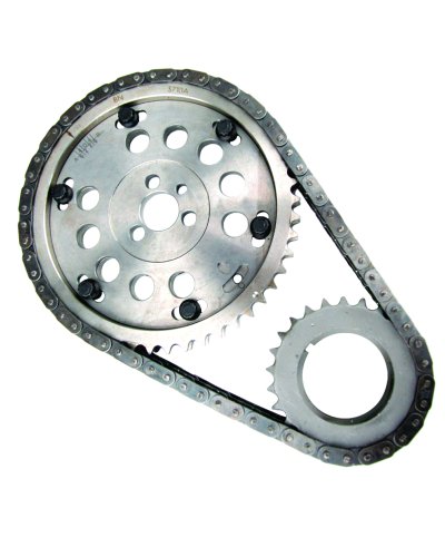
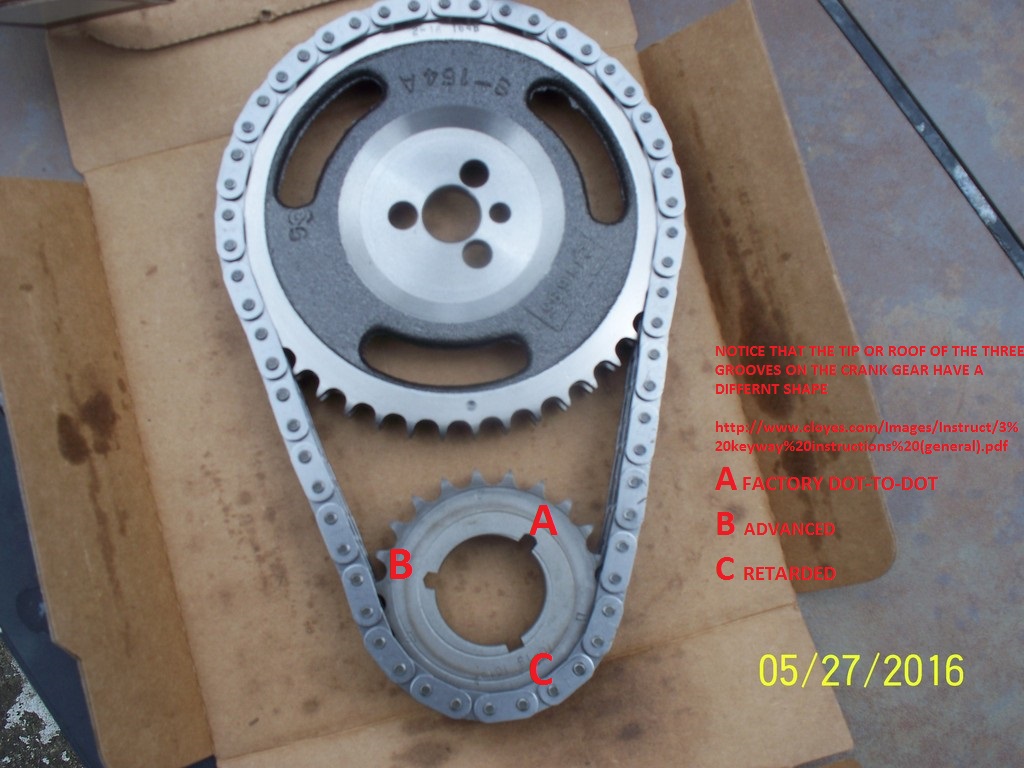
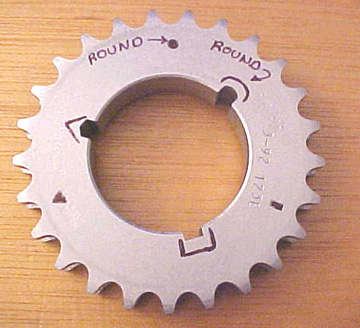
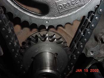
notice the approximate location and relationship between the cam pin and crank key
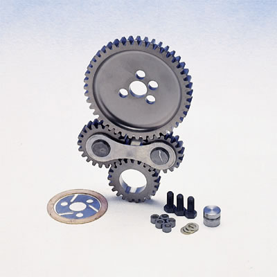
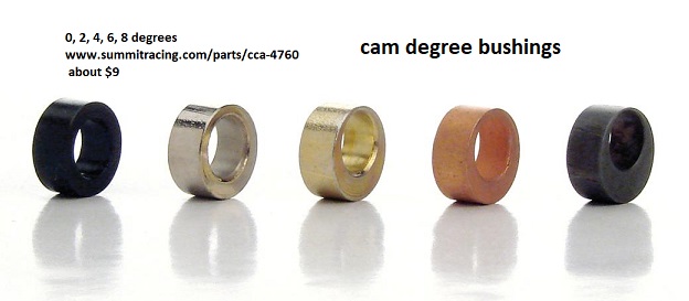
there are fully adjustable timing gear sets available
http://www.usaperform.com/timing-chain- ... =4d&page=1
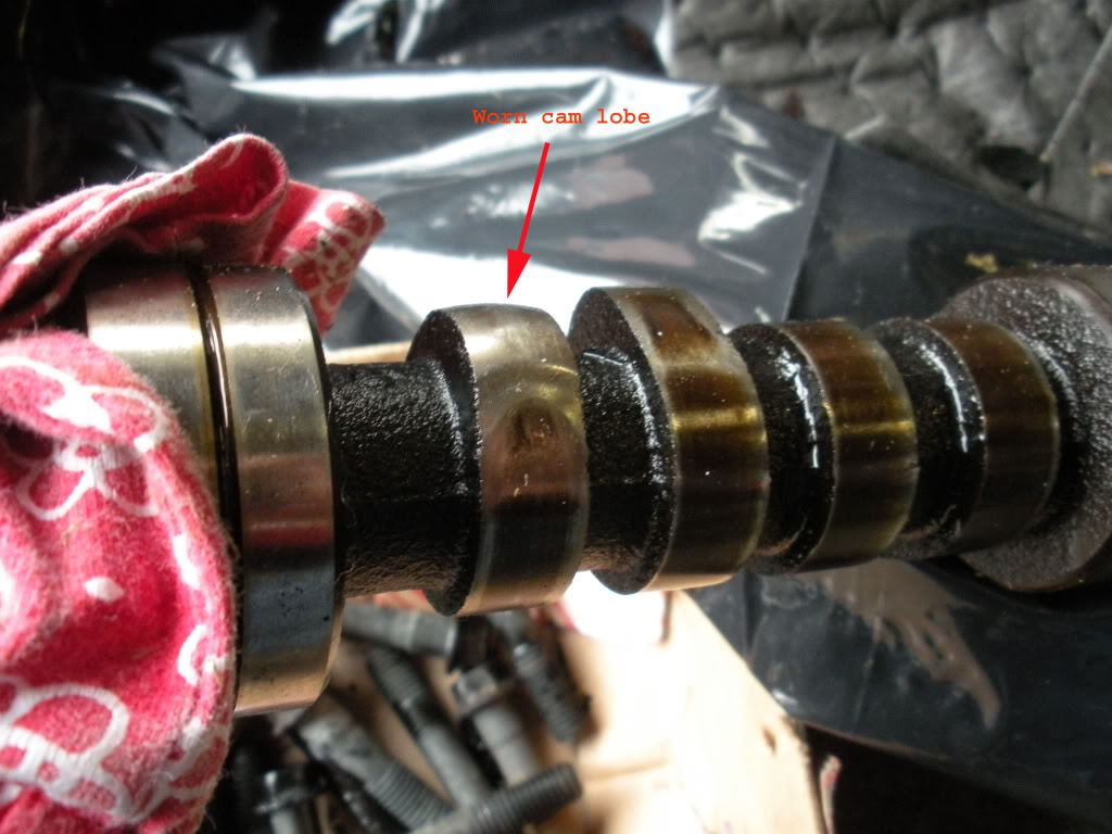
OK lets go into the problem,and info on potential solutions
(the failed cam lobe to lifter contact and rapid unacceptable wear area)
theres several routes or areas of concern, to look into
Proper clearances,
proper valve train geometry,
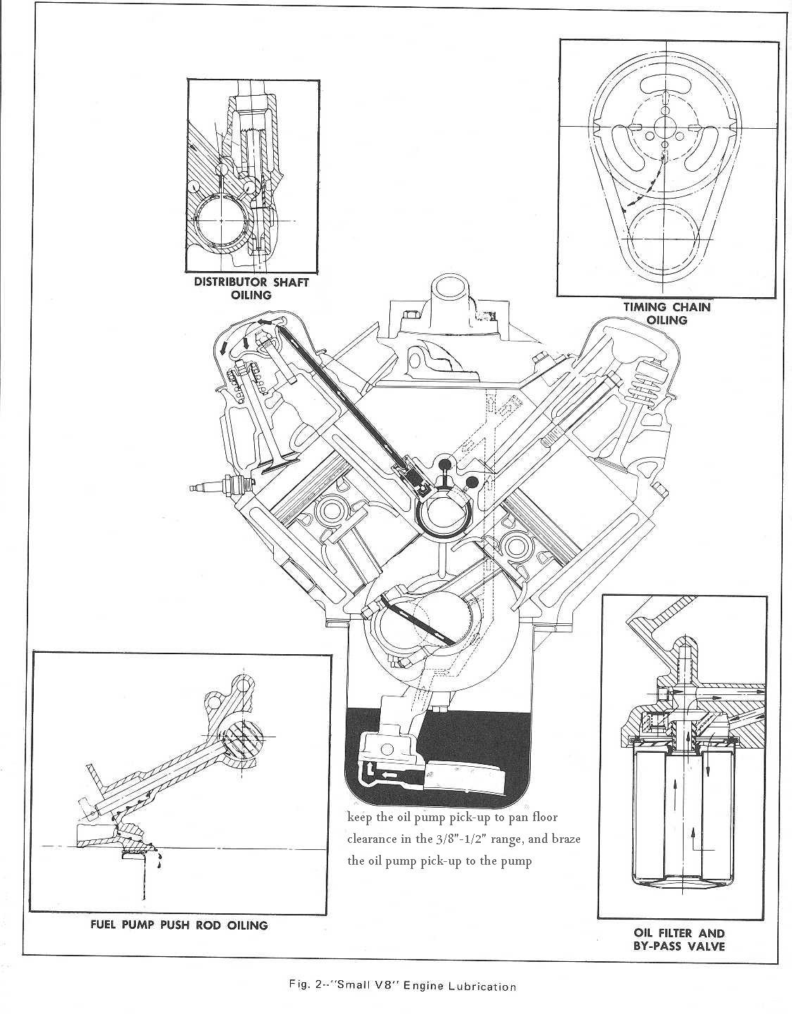
lubrication,
cooling,
protection from, and containment of metallic debris, generated through wear.
before, you start reading through the thread and links below, Ill point out that I,ve done the forensics on quite a few failed cams over the years that guys have brought to my shop and
Id say about
60% of the failed cam lobe & lifter problems were traced to a failure to check clearances or correct valve train geometry issues , like coil bind, rocker to rocker stud, or rocker to adjustment nut clearance, retainer to valve seal, clearances or rocker geometry, use of the wrong spring load rates for the application,or failure to check valve train or push rods binding issues like rocker to retainer, push rods binding on guide plates or heads,etc.before they became an issue.
about
10% were traced to failure to remove metallic or other trash, generated by a previous cam failing from the engines internal oil passages, or failure to carefully clean the engine before installing the new cam, and components, ( use of shrapnel screens and magnets help a great deal in this but can,t remove all trash as some is non-magnetic)
5% to low quality components, or miss matched parts, like the wrong spring load rates for the application, and perhaps
15% of the failures due to using the wrong lubricants , or not nearly enough moly cam lube on the lobes and lifter bases or setting up the oil supply system correctly, or use of a high quality oil and filter, and a failure to change that oil and filter regularly after the first few hundred miles , the remaining
1o% were from unknown causes but more than likely due to a failure to correctly break in the cam,or properly adjust the valves before the engine break-in process or carefully check and re-adjust the lifters rapidly during the break-in process
its likely cause
most of the imported crap has quality control issues and the PBM stuff ,and Chinese import stuff
and most other import parts are rather well known for that
I once used a timing set a buddy bought, for $11 at a auto parts store close out bin,
a SBC timing gear/chain set imported from India,
that had the tdc index vs the key-way location, 11 degrees off of true tdc,
if you used that timing set with the dot-to-dot cam install vs,
using a degree wheel install, it would be off index significantly,
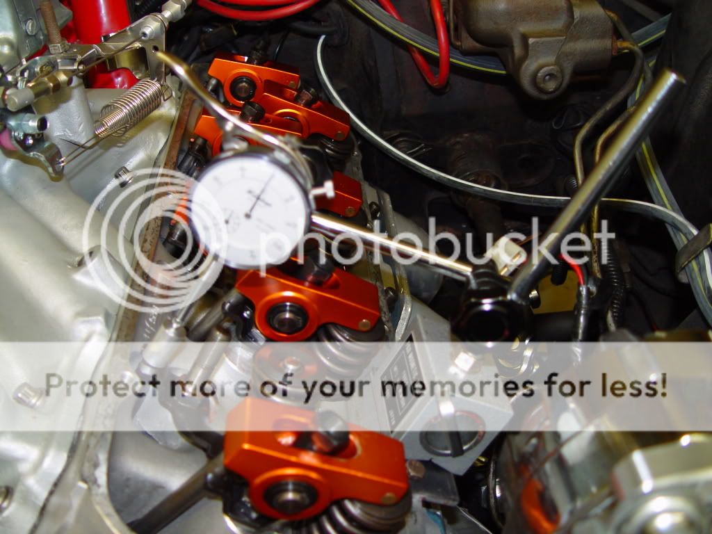
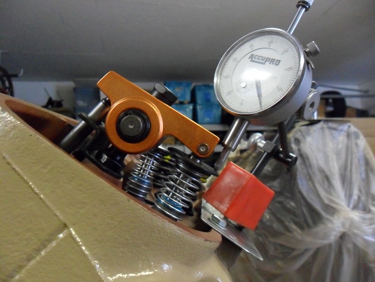
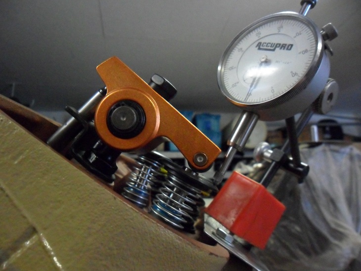
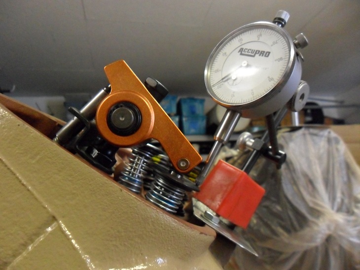
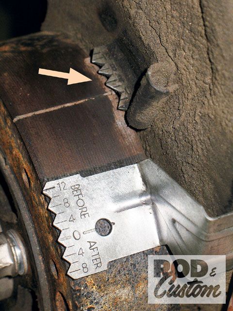
we found out how off index it was using a degree wheel and dial indicator cam install
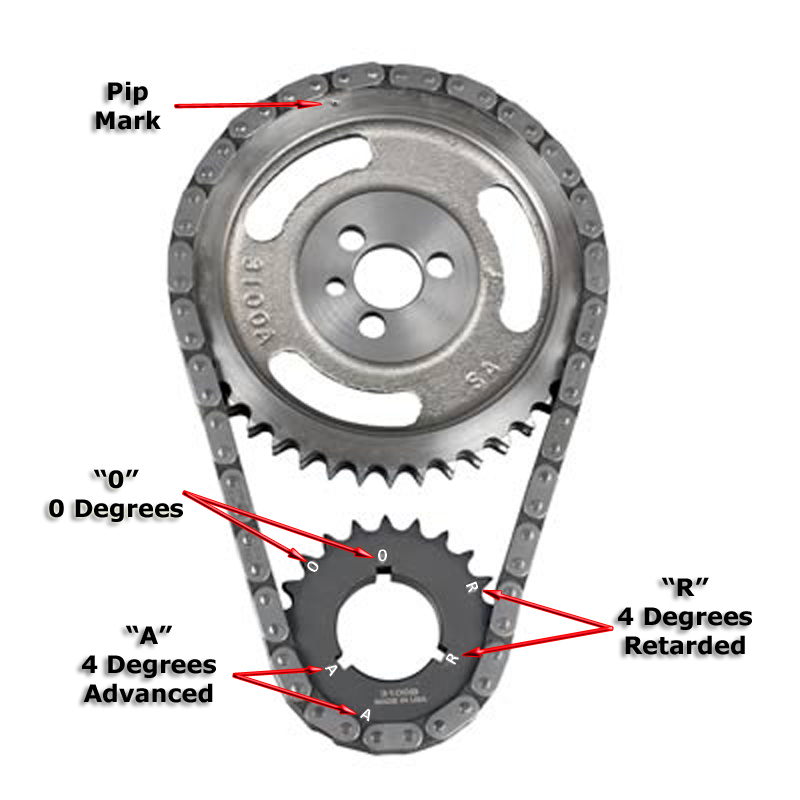
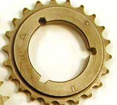
many guys don,t understand that on these multi key timing sets there areTHREE different letters,
on the crank gear and three matching keyway slots.
0 on the cam gear gets lined up with 0 on the crank gear, if the 0 crank key slot is used to index the cam at TDC
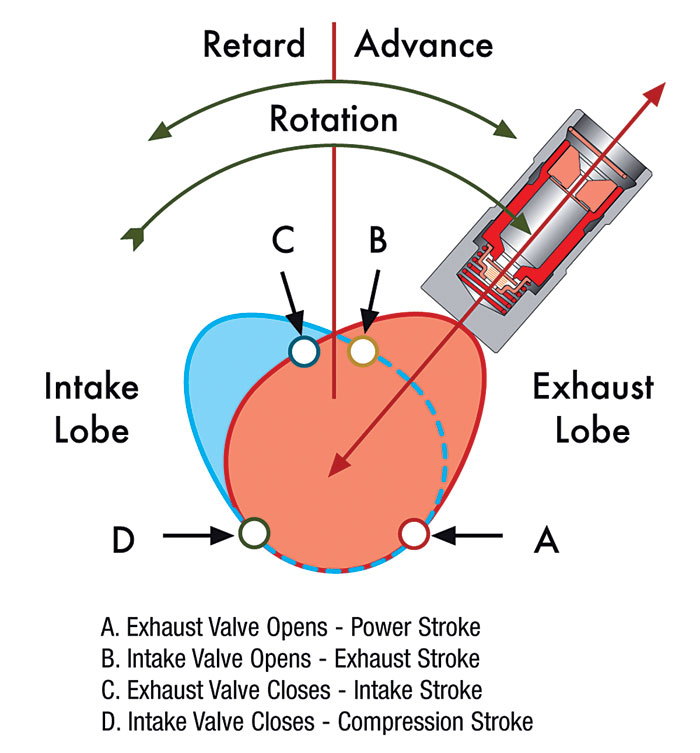
0 on the cam gear gets lined up with R on the crank gear, if the R crank key slot is used to index the cam at 4 degrees retarded from TDC
0 on the cam gear gets lined up with A on the crank gear, if the A crank key slot is used to index the cam at 4 degrees ADVANCED from TDC
http://www.superchevy.com/technical/eng ... index.html

http://store.summitracing.com/partdetai ... toview=sku
http://www.romac.com.au/Std_&_Offset_Crank_Info.pdf
read thru the links and info on these old threads
http://www.iskycams.com/pdfcatalog/2004-05/page195.pdf
http://www.pbm-erson.com/uploads/cat%5B ... CEDURE.pdf
viewtopic.php?f=53&t=279&p=1640#p1640
http://www.carcraft.com/howto/116_0701_ ... index.html
viewtopic.php?f=52&t=966&p=1682&hilit=+dead#p1682
http://www.thedirtforum.com/chevyvalves.htm
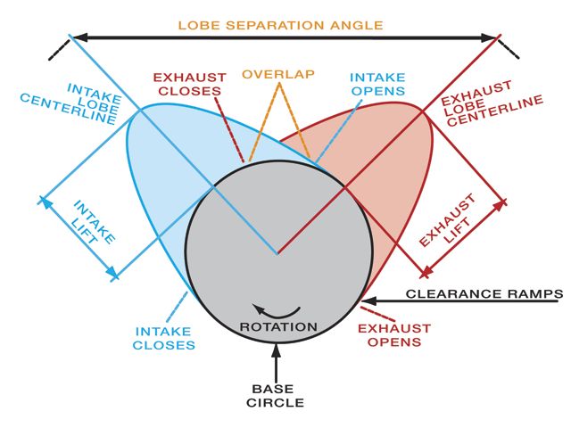
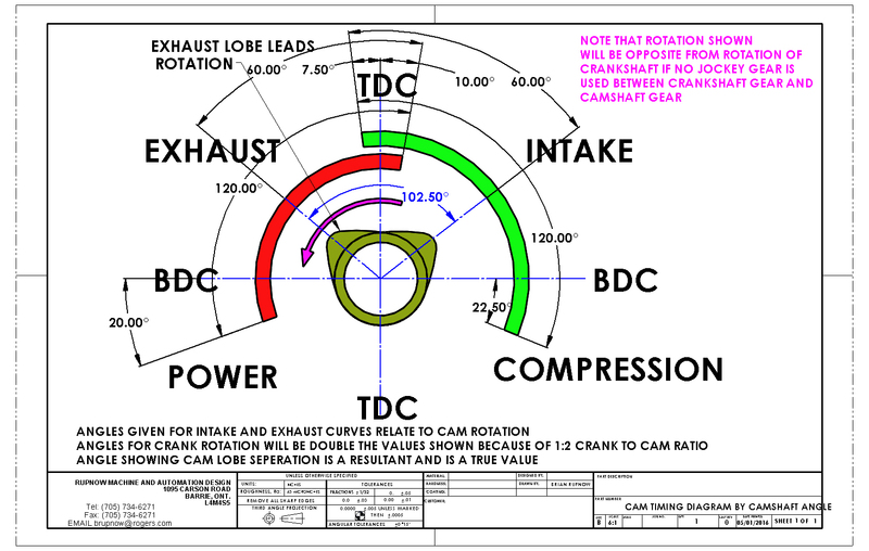
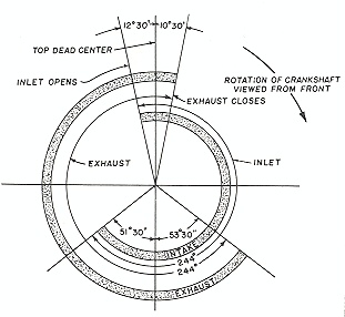
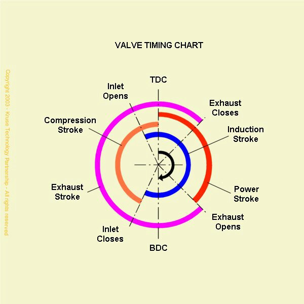
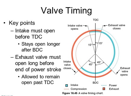
http://cochise.uia.net/pkelley2/Overlap.html
http://www.2quicknovas.com/happyvalves.html
http://www.jimcookperformance.com/TechNotes/TN7ValvLash.html
http://www.centuryperformance.com/valveadjustment.asp
http://www.babcox.com/editorial/us/uhs89720.htm
http://www.boostandfuel.com/support/setting_valves.htm
http://www.carcraft.com/techarticles/87998/index2.html
http://www.xtrememotorworks.com/cam_basics.htm
http://www.angelfire.com/fl4/pontiacdude428/valveadj.html
http://www.lbfun.com/warehouse/tech_inf ... 0Paper.pdf
btw on roller cams, roller rockers, and roller lifters and timing chains this stuff works ok as a lube
http://www.summitracing.com/parts/MEL-M-10012

http://www.chevytalk.org/threads/showfla...rue#Post1178811
http://www.cranecams.com/?show=browsePa ... er=11991-1
this may help
if you've got an older GM muscle car with timing problems this thread below may explain it
BE AWARE OF FAKE BRAND NAME PARTS AT DISCOUNT PRICES
I once purchased a bunch of chevy valve train parts from a local auto parts vendors shop that was going out of business, among those was a " CLONE OF A CLOYES" timing chain and timing gear set, it looked identical but it said in very small print under the timing gears printed where you could not see it with the shrink wrap holding the parts to the cardboard backer (which had CLOYES) written in 1" high red letters on the package, "made in india" it proved to be 11 degrees advanced in the DOT-TO-DOT config when a degree wheel was used
DOT-TO-DOT
DOING IT CORRECTLY

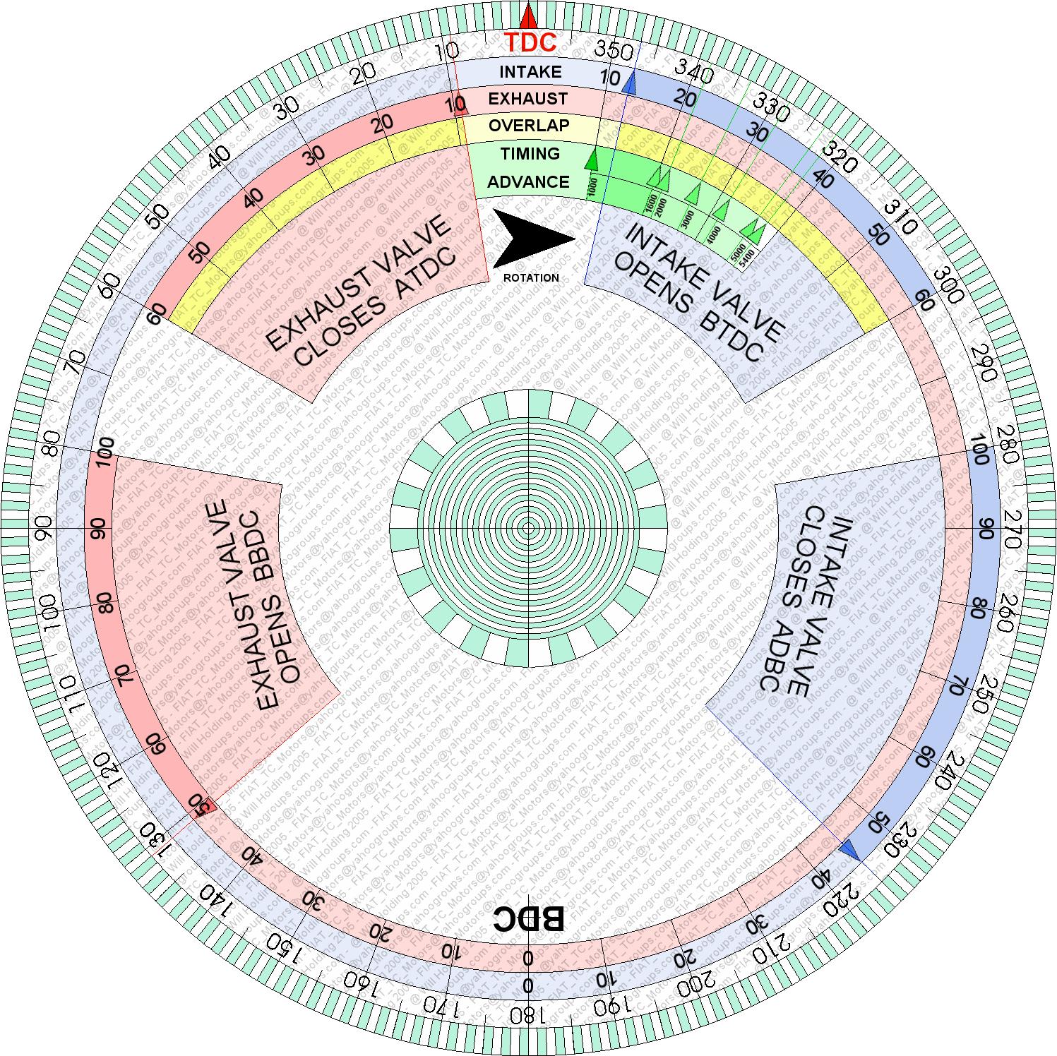
heres a printable degree wheel
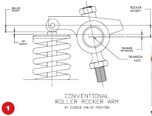
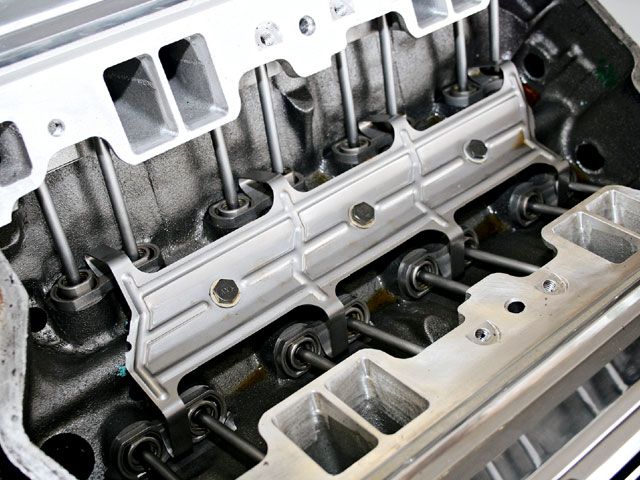
what the stock OEM roller lifter valve train looks like
(btw when using a piston stop tool
if your standard strait probe/stop tool is not touching the piston due to the shallow entrance angle
youll want to remove ALL the spark plugs and back off ALL the rockers
on not only cylinder number one ,
but all the cylinders ,
so you can feel the engine as it moves/rotates
and make sure the cars not in gear so that the engine can be rotated much more easily when done manually,
this prevents the valves in cylinder number one from opening and removing the other spark plugs greatly reduces resistance due to compression.
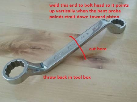
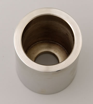
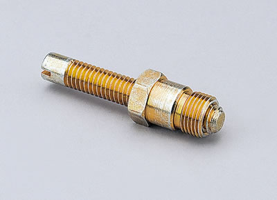
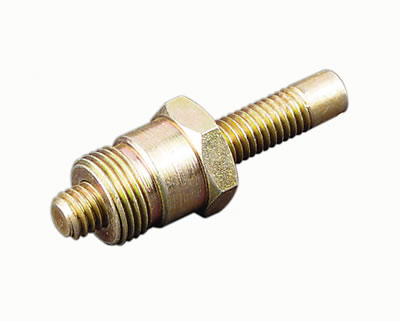
yes your problem, is FAR from rare and in fact its very common most guys simply take an old spark plug,
put it in a vise and bust out the old porcilian center and re-thread the interior of the remaining metal hex.
or buy a tool like comps
https://www.summitracing.com/parts/...-_-comp-cams&gclid=CJ3wuuyJ8tACFYOFswodCKYKvw
you then buy a 6" threaded bolt, screw it into the plug body
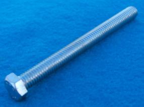
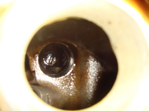
be aware that on BBC engines with flat top pistons that probe bolt must be extended rather deeply ,
to contact the piston, simply because the plug thread angle is so shallow, this also means you'll want to remove all the spark plugs and make damn sure the engines in neutral when you manually turn the engine over so you easily feel the probe bolt contact the piston,
you don't want to bend the piston stop probe bolt or damage a piston crown,
bending a valve, or be fighting valve spring resistance
with similar thread pitch and thread that fully threaded bolt about 3" of that bolt extending past the spark plug base,
it basically comes down to, a question of do you accept a random install where the timing can be almost any place randomly or do you insist on maximizing the engines potential and know exactly how and why things work.
when your degreeing in a cam your verifying that the cam card figures , you purchased the cam for MATCH what the cams going to be doing in the engine , if everything is correct a dot-to-dot install will be almost identical, but the fact is that due to manufacturing tolerances a dot-to-dot install will frequently be a few degrees off!
almost EVERY manufacturer grinds their cams 4 degrees advanced if installed with the dot-to-dot install method, this is almost standard practice, it was and is done to marginally boost the cams lower to mid range torque, now most guys might never notice, but it can and frequently does effects the engines power band so getting it correct helps and eliminates one potential source of problems (be damn sure you verify the cams degreed in correctly and the ignition firing orders correct and all the distributor wires go to the correct cylinder,s spark plugs and distributor cap locations)
ITS also a great way to catch mistakes before you get to the point where you try to start the engine with the cam indexed incorrectly, if you used the wrong index marks on the timing set..
WELL,theres manufacturing tolerances in all machined components , in most case the tolerances are rather random to some degree and tend to cancel out the differences between the components to some degree, and the AVERAGE result is that most of the time if your, cams a few degrees off, the ideal location most people will never know it and that's fine, but occasionally the tolerances stack up to cause a problem, or clearance issues.
you can easily find a few degrees of cam timing difference can cause or cure detonation problems or (PINGING) under loads, and in a few cases piston to valve clearance is critical, once you get into building performance engines you'll also find that the intake and exhaust are ideally tuned for a set power band and having the cam a few degrees off from the ideal will cost you some power.
you can install most cams with the common (DOT-TO-DOT) timing set marks if you use quality components like CLOYES timing sets and name brand cams but even then theres variations that youll see once you degree in the cam rather than assume its correctly indexed
and using the dot-to-dot route youll be within about 2-3 degrees in most cases, which is close enough to get the car to run decent, but a 4 degree change results in about a 200rpm change in the cars power band RPM range, the tolerances can result in a 3-7 degree off set with the cheap import timing sets and cheaper mass produced cams, in most cases you'll never notice, but if the cars set up to run with close tolerances, high compression and ideal quench ETC. that could easily result in 10-20hp, IVE seen some cases where the difference was quite noticeable, in the way the car ran, and a few cases where cheap import timing sets were WAY OFF and would have cost you a good deal of hp/tq at least and probably caused clearance issues, or over heating or a noticeable power loss if installed without checking.
theres also more to it than just INDEXING the cam, you need to set up the valve train geometry and check spring rates and clearances carefully, and indexing the cam timing in the engine in relation to the piston location, during its rotation can be a valuable tuning aid , as you can easily degree in a cam so its 4-6 degrees advanced or retarded from the split overlap or strait up location, easily tuning the power band up to about 200-250 rpm either direction in the rpm band, changing the opening and closing points in the cam timing, effects the DCR and the power band, but its also useful in getting the intake and exhaust tuned but past those limits swapping to a different cam is almost always the better choice
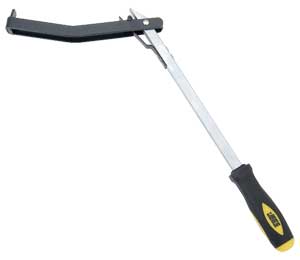
BTW I assume you gentlemen do know theres
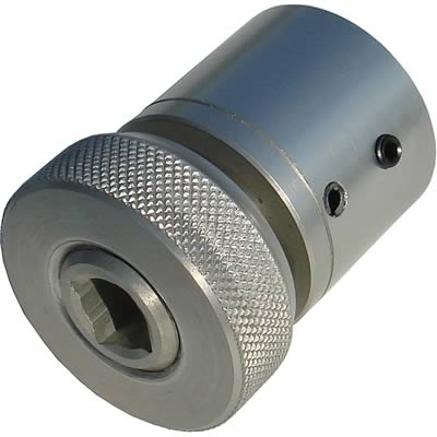
even a correct and very inexpensive tool for spinning it from the flex-plate or flywheel,
once the cylinder heads are installed,
so your not stressing the damper retention bolt spinning the engine over manually, If you need to verify TDC and your cylinder heads are still on,
it's done all the time, read these threads linked below carefully
you need a degree wheel, that bolts to the crank snout
Use of a crank snout adapter and removing the damper is prefered but not required
and a piston stop that screws in where the spark plug normally goes
http://garage.grumpysperformance.co...ng-cam-and-shifting-the-lca.10553/#post-44949
http://garage.grumpysperformance.co...op-dead-center-1-for-timing-ignition-cam.966/
http://garage.grumpysperformance.com/index.php?threads/turning-your-crank-manually.5933/
https://www.summitracing.com/parts/wmr-w80510/overview/
https://www.summitracing.com/parts/sum-900178/overview/
http://www.cranecams.com/bulletins_listview.php?s_id=7
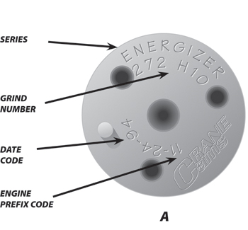
most manufacturers IDENTIFY OR mark cams under the timing gear mount surface
READING THRU the linked info below will help,a great deal, and yes IM well aware theres a ton of info posted in the links, reading and understanding that info will be to your benefit, well beyond the time it takes you to read thru it, and it can easily save you many hours and avoid costly repairs by doing the reading before you need to do repairs, due to over-looked steps or incorrectly installed parts
Cam timing for REAL power and the automatic cam degree wheel
In this, episode 73, DV goes into the techniques he uses for getting the cam timing right for max power and that is rarely what the cam companies recommend. ...
www.youtube.com
How to Degree a Camshaft: Lobe Center Method
In this instructional video, Nic Woods of Clay Smith Cams walks customers through the process of degreeing in a Clay Smith Camshaft using the "Lobe Center Me...
www.youtube.com
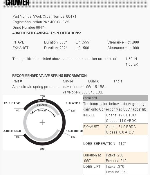
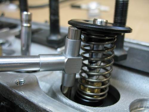
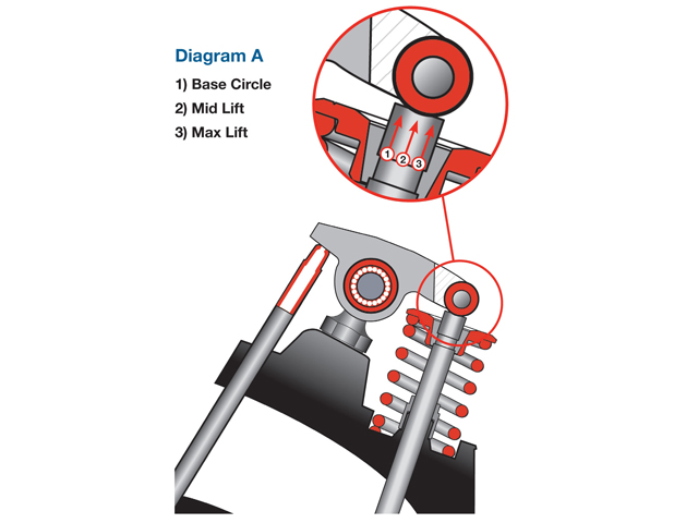
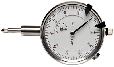
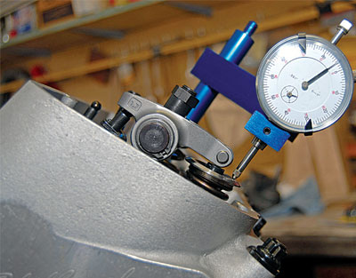
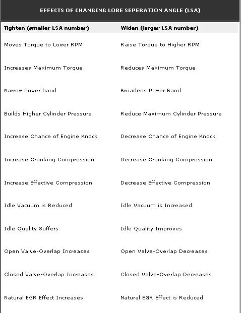
A non-symmetrical lobe will have a different center-line when
checked at 0.050†above the base circle than it does when checked at 0.050†from either side of the top of the lobe.
camshafts should always be checked at the bottom of the lobe, which is 0.050†tappet lift off the base circle.
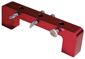
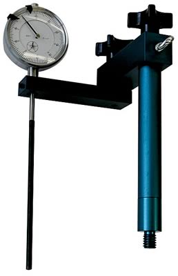
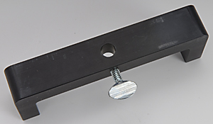
Proform Parts 66830 - Proform Cam Checking Fixture Kits
THE PROFORM SOCKETS ARE ALUMINUM
http://www.summitracing.com/parts/PRO-67492/
http://garage.grumpysperformance.co...op-dead-center-1-for-timing-ignition-cam.966/
http://www.summitracing.com/parts/PRO-67491/
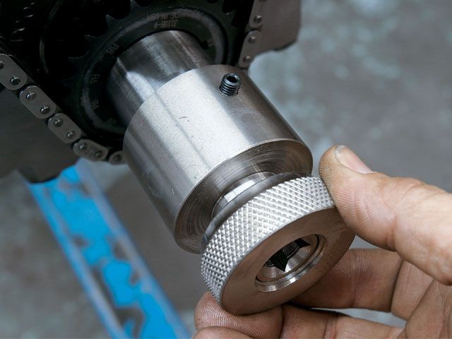
if your wondering how to turn a crank over to do test and diagnosing and cam installs you will benefit from the proper tools
IF you remove the spark plugs and take the car out of gear its fairly safe to turn the engine over manually,
using a breaker bar on the cranks damper retainer bolt,the problem is 99.9% of us are LAZY,
and just try it as the engine sits and eventually we strip the crank bolt or the crank snout threads
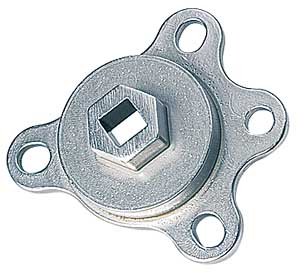
If the damper been removed the crank snout socket thats designed for your crank to turn the crank.
and hold the degree wheel while degreeing in the cam will be the route to take
shop carefully and ask questions the sockets and tools don,t fit universally, you'll need an assortment of several OF EACH TYPE ONCE YOU GET INTO ENGINE BUILDING SERIOUSLY
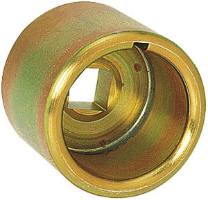
the crank socket like this that can turn the crank safely and firmly and accurately mount a degree wheel is prefered
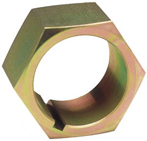
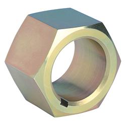
there are also crank turning nuts that fit individual crank sizes
most of us are too lazy to remove the damper/balancers
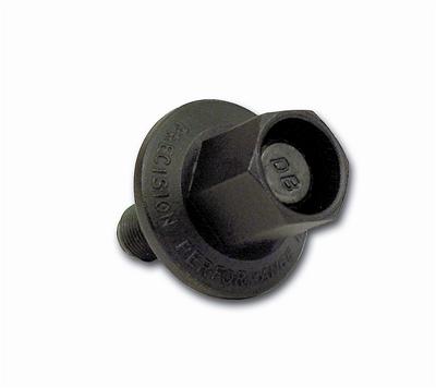
there are over size extra strength damper bolts for sale that are less likely to strip
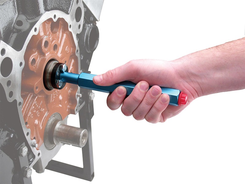
they sell an engine damper bolt on tool that fits some dampers that allows you to use a 1/2" breaker bar rather easily
http://www.summitracing.com/parts/pro-66782?seid=srese1&gclid=CNqD0YXA48gCFUYYHwodBJ4DVA
IT MAKES LITTLE SENSE TO BUY the sockets that don.t have the provision for mounting the cam degree wheel to save a few dollars in my opinion
when purchasing a crank socket try to find one designed to easily accept and lock down a degree wheel
THE COMP SOCKETS ARE FAR MORE DURABLE STEEL
http://www.jegs.com/i/COMP+Cams/249/4914/10002/-1 LS ENGINES
http://www.jegs.com/i/COMP-Cams/249/479 ... ProductId= BBC ENGINES
http://www.jegs.com/i/COMP-Cams/249/479 ... ProductId= SBC ENGINES
a properly installed nylon cam button with a bolt retainer plates a good idea
youll generally use LOC-TITE on the retainer bolts threads
youll generally use LOC-TITE on the retainer bolts threads
use loc-tight on the bolt threads to reduce any tendency for them coming loose
a properly installed nylon cam button with a bolt retainer plates a good idea
http://www.tavia.com/free_degree_wheel.html
WHEN CRANK IS AT TWELVE AND CAM IS AT SIX THEN #6 CYL IS FIRING AFTER YOU LINE UP YOUR MARKS AND INSTALL GEAR THEN ROTATE YOUR CRANK ONE REVOLUTION AND THEN DROP THE DIST. IN - AT THAT POINT
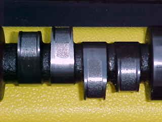
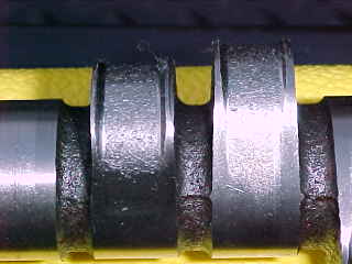
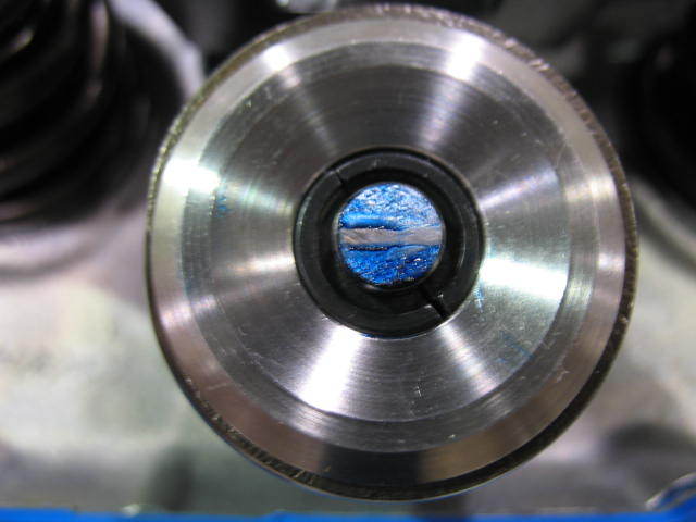
Starting in 1987 GM began using a hydraulic roller cam in their production car engines.
This required a cam thrust plate on the front of the block.
The step in the nose of this cam (left) identifies it as a cam intended for use in a production roller cam block.
If your ever in doubt, about the correct timing chain application,
CALL THE TECH GUYS AT CLOYES
cloyes tech dept 1-479-646-1662 EXT 228
with the older style non-step nose cam, in the newer style "08" block, you will NOT use the retainer plate
you should use a cloyes 9-3100 timing chain, set
https://www.summitracing.com/parts/clo-9-3100
http://garage.grumpysperformance.com/index.php?threads/semi-fool-proof-cam-sellection.82/
http://garage.grumpysperformance.co...hanics-of-adv-ret-a-camshaft.4532/#post-12050
http://garage.grumpysperformance.com/index.php?threads/cam-drive-details.3809/#post-10226
http://garage.grumpysperformance.com/index.php?threads/wear-plate.3777/#post-10011
you need to be very careful, as imitation/fake name brand parts from china/india are being sold
if there's any money to be scammed from the un-aware , there's surely someone out there, ready to take their cash in a heartbeat selling crap quality goods. unless you deal DIRECTLY with the name brand vendor, or in some cases even some larger parts houses you take a chance on getting crap...
garage.grumpysperformance.com
http://www.wallaceracing.com/cam-deg-calc.php
http://www.hughesengines.com/Upload/pro ... ar2010.pdf
http://69.20.53.62/pdf/803.pdf
http://www.iskycams.com/degreeing.html
http://garage.grumpysperformance.co...e-springs-and-setting-up-the-valve-train.181/
http://www.thedirtforum.com/degree.htm
http://www.lunatipower.com/Tech/Cams/Ho ... eACam.aspx
viewtopic.php?f=52&t=399&p=1689#p1689
http://www.streetsideauto.com/images/BB ... e/214e.pdf
http://garage.grumpysperformance.com/index.php?threads/chain-vs-gear-drive-cam.781/#post-72280
http://www.classicinlines.com/cam_degree.asp
http://www.lunatipower.com/Tech/Cams/CamSpecTerms.aspx
http://cranecams.com/?id=2&show=faq
http://www.jegs.com/InstallationInstruc ... 119661.pdf
http://www.aa1car.com/library/camshafts.htm
viewtopic.php?f=52&t=1070&p=2054#p2054
http://www.harborfreight.com/cpi/ctaf/d ... umber=5645
http://www.thirdgen.org/sbc-camshafts-primer
https://www.holley.com/data/Products/Te ... NST150.pdf
http://www.cam-shield.com/index.html
http://www.camshaftinnovations.com/FTT_ ... ingCam.htm
http://garage.grumpysperformance.com/index.php?threads/upgrade-choices.11416/
http://www.trishieldperf.com/cam_degreeing.htm
http://www.faliconcranks.com/pdf/degree ... mshaft.pdf
http://www.ls1howto.com/index.php?article=23
LINK TO INFO ON A printable degree wheel and related info
viewtopic.php?f=52&t=974
The following Mechanical operating clearances must always be verified to ensure proper operation of the camshaft:
Spring coil bind clearance
Retainer to seal/valve guide boss clearance
Piston to valve clearance
Rocker arm slot to stud clearance
Camshaft endplay
Distributor shaft and gear endplay
Connecting rod to cam clearance
Proper hydraulic lifter pre-load or lash clearance
Proper valvetrain geometry
proper spring load rates
rocker to retainer clearance
notice the approximate location and relationship between the cam pin and crank key
there are fully adjustable timing gear sets available
http://www.usaperform.com/timing-chain- ... =4d&page=1
OK lets go into the problem,and info on potential solutions
(the failed cam lobe to lifter contact and rapid unacceptable wear area)
theres several routes or areas of concern, to look into
Proper clearances,
proper valve train geometry,
lubrication,
cooling,
protection from, and containment of metallic debris, generated through wear.
before, you start reading through the thread and links below, Ill point out that I,ve done the forensics on quite a few failed cams over the years that guys have brought to my shop and
Id say about
60% of the failed cam lobe & lifter problems were traced to a failure to check clearances or correct valve train geometry issues , like coil bind, rocker to rocker stud, or rocker to adjustment nut clearance, retainer to valve seal, clearances or rocker geometry, use of the wrong spring load rates for the application,or failure to check valve train or push rods binding issues like rocker to retainer, push rods binding on guide plates or heads,etc.before they became an issue.
about
10% were traced to failure to remove metallic or other trash, generated by a previous cam failing from the engines internal oil passages, or failure to carefully clean the engine before installing the new cam, and components, ( use of shrapnel screens and magnets help a great deal in this but can,t remove all trash as some is non-magnetic)
5% to low quality components, or miss matched parts, like the wrong spring load rates for the application, and perhaps
15% of the failures due to using the wrong lubricants , or not nearly enough moly cam lube on the lobes and lifter bases or setting up the oil supply system correctly, or use of a high quality oil and filter, and a failure to change that oil and filter regularly after the first few hundred miles , the remaining
1o% were from unknown causes but more than likely due to a failure to correctly break in the cam,or properly adjust the valves before the engine break-in process or carefully check and re-adjust the lifters rapidly during the break-in process
its likely cause
most of the imported crap has quality control issues and the PBM stuff ,and Chinese import stuff
and most other import parts are rather well known for that
I once used a timing set a buddy bought, for $11 at a auto parts store close out bin,
a SBC timing gear/chain set imported from India,
that had the tdc index vs the key-way location, 11 degrees off of true tdc,
if you used that timing set with the dot-to-dot cam install vs,
using a degree wheel install, it would be off index significantly,
we found out how off index it was using a degree wheel and dial indicator cam install
many guys don,t understand that on these multi key timing sets there areTHREE different letters,
on the crank gear and three matching keyway slots.
0 on the cam gear gets lined up with 0 on the crank gear, if the 0 crank key slot is used to index the cam at TDC
0 on the cam gear gets lined up with R on the crank gear, if the R crank key slot is used to index the cam at 4 degrees retarded from TDC
0 on the cam gear gets lined up with A on the crank gear, if the A crank key slot is used to index the cam at 4 degrees ADVANCED from TDC
http://www.superchevy.com/technical/eng ... index.html
http://store.summitracing.com/partdetai ... toview=sku
http://www.romac.com.au/Std_&_Offset_Crank_Info.pdf
read thru the links and info on these old threads
http://www.iskycams.com/pdfcatalog/2004-05/page195.pdf
http://www.pbm-erson.com/uploads/cat%5B ... CEDURE.pdf
viewtopic.php?f=53&t=279&p=1640#p1640
http://www.carcraft.com/howto/116_0701_ ... index.html
viewtopic.php?f=52&t=966&p=1682&hilit=+dead#p1682
http://www.thedirtforum.com/chevyvalves.htm
http://cochise.uia.net/pkelley2/Overlap.html
http://www.2quicknovas.com/happyvalves.html
http://www.jimcookperformance.com/TechNotes/TN7ValvLash.html
http://www.centuryperformance.com/valveadjustment.asp
http://www.babcox.com/editorial/us/uhs89720.htm
http://www.boostandfuel.com/support/setting_valves.htm
http://www.carcraft.com/techarticles/87998/index2.html
http://www.xtrememotorworks.com/cam_basics.htm
http://www.angelfire.com/fl4/pontiacdude428/valveadj.html
http://www.lbfun.com/warehouse/tech_inf ... 0Paper.pdf
btw on roller cams, roller rockers, and roller lifters and timing chains this stuff works ok as a lube
http://www.summitracing.com/parts/MEL-M-10012
http://www.chevytalk.org/threads/showfla...rue#Post1178811
http://www.cranecams.com/?show=browsePa ... er=11991-1
this may help
if you've got an older GM muscle car with timing problems this thread below may explain it
BE AWARE OF FAKE BRAND NAME PARTS AT DISCOUNT PRICES
I once purchased a bunch of chevy valve train parts from a local auto parts vendors shop that was going out of business, among those was a " CLONE OF A CLOYES" timing chain and timing gear set, it looked identical but it said in very small print under the timing gears printed where you could not see it with the shrink wrap holding the parts to the cardboard backer (which had CLOYES) written in 1" high red letters on the package, "made in india" it proved to be 11 degrees advanced in the DOT-TO-DOT config when a degree wheel was used
DOT-TO-DOT
DOING IT CORRECTLY
heres a printable degree wheel
what the stock OEM roller lifter valve train looks like
(btw when using a piston stop tool
if your standard strait probe/stop tool is not touching the piston due to the shallow entrance angle
youll want to remove ALL the spark plugs and back off ALL the rockers
on not only cylinder number one ,
but all the cylinders ,
so you can feel the engine as it moves/rotates
and make sure the cars not in gear so that the engine can be rotated much more easily when done manually,
this prevents the valves in cylinder number one from opening and removing the other spark plugs greatly reduces resistance due to compression.
yes your problem, is FAR from rare and in fact its very common most guys simply take an old spark plug,
put it in a vise and bust out the old porcilian center and re-thread the interior of the remaining metal hex.
or buy a tool like comps
https://www.summitracing.com/parts/...-_-comp-cams&gclid=CJ3wuuyJ8tACFYOFswodCKYKvw
you then buy a 6" threaded bolt, screw it into the plug body
be aware that on BBC engines with flat top pistons that probe bolt must be extended rather deeply ,
to contact the piston, simply because the plug thread angle is so shallow, this also means you'll want to remove all the spark plugs and make damn sure the engines in neutral when you manually turn the engine over so you easily feel the probe bolt contact the piston,
you don't want to bend the piston stop probe bolt or damage a piston crown,
bending a valve, or be fighting valve spring resistance
with similar thread pitch and thread that fully threaded bolt about 3" of that bolt extending past the spark plug base,
Last edited by a moderator: