You are using an out of date browser. It may not display this or other websites correctly.
You should upgrade or use an alternative browser.
You should upgrade or use an alternative browser.
Distance Behind X Pipe?
- Thread starter busterrm
- Start date
busterrm
solid fixture here in the forum
Rick, let me ask this so I understand all the data: 1. 25.499 is the length the collector needs to be correct? 2. Harmonics - 38.125-40.690 inches is the total length to end of the collector correct? 3. 1.674 pipe diameter is the inside diameter of the tube correct?

YesRick, let me ask this so I understand all the data: 1. 25.499 is the length the collector needs to be correct?
No, those numbers are for the primary tubes only.2. Harmonics - 38.125-40.690 inches is the total length to end of the collector correct?
I need to look back at what I did, but since it show the wall thickness to be .065"/16 gauge, I'm betting that 1.674 is the OD. It's up to you decide what is the closest actual OD you can buy.3. 1.674 pipe diameter is the inside diameter of the tube correct?
I can't stand behind these number since you want to use my engine parameters. You have AFR and I have Brodix, the actual centerline port lengths both intake and exhaust are going to be different. Then there is also the both port volumes, I used a barrette to measure these so I would know exactly what the numbers would be, NOT the advertised numbers. OH, then there is also the intake manifold ports ???
if in doubt, about the header component size and length etc.
always assume a marginally ,or a bit longer primary tube and marginally smaller diameter collector, to be a valid choice.
as this tends to slightly favor the mid rpm ranges,
of a bit shorter length exiting to a LARGER diameter exhaust.
(preferably with an X-pipe within as close a distance as possible and low flow restriction muffler's)
will work rather well.
keep in mind the scavenging efficiency changes with rpms, displacement and compression ratio as well as with the ignition timing
fuel air ratio , valve sizes, port flow rates and exhaust gas temps, so minor changes in length/diameter etc.
only marginally change where in the rpm range peak cylinder scavenging efficiency occurs,
minor changes won't be very noticeable, could you even begin to feel a peak scavenging efficiency or peak power,
if the difference was 30-60 rpm difference? as you run up through the gears, remember you might only be in a gear, for a couple seconds,
and during that couple seconds the engine might go from 5500rpm-6800rpm on an engine you built for performance use,
and while a street engine may be in a gear between shifts marginally longer ,
and may operate at only lets say 4500rpm-5900rpm that 30-60 rpm difference will be only seen on a precise dyno,
and that peak power last less than a fraction of a single second at best during a gear change.
so don,t sweat minor changes in collector or primary tube length.
Last edited:
busterrm
solid fixture here in the forum
Hmm, once I have the funds to gather the parts and welder, I will have to stew on it and make a decision on how to move forward. I just want a exhaust that isn't going to rob potential tq and hp, with the mid length headers I have now and the smaller 2 1/4 exhaust I don't feel it will breath like it should and scavenge like it should.
busterrm
solid fixture here in the forum
The thing is Rick, you have unlimited ability with your T bucket, I don’t have that I am limited to fitting into certain space. The collector length I can probably match, the OD of my primaries will be 1 3/4, the length of each tube is going to be hard to match with confines of space I am afforded. I will just do the best with what I have, but I am sure it will be better than 1 5/8 mid length headers and 2 1/4 exhaust system!Yes
No, those numbers are for the primary tubes only.
I need to look back at what I did, but since it show the wall thickness to be .065"/16 gauge, I'm betting that 1.674 is the OD. It's up to you decide what is the closest actual OD you can buy.
I can't stand behind these number since you want to use my engine parameters. You have AFR and I have Brodix, the actual centerline port lengths both intake and exhaust are going to be different. Then there is also the both port volumes, I used a barrette to measure these so I would know exactly what the numbers would be, NOT the advertised numbers. OH, then there is also the intake manifold ports ???
View attachment 14842
I do appreciate your help, it gave me a starting point. I am sure I can improve on what I have, really I prefer Daytona style exhaust systems any way!
No problem Bob. Using PipeMax is considerably more labor intensive to gather the numbers thatI do appreciate your help, it gave me a starting point.
will be the inputs to the program. Things like port lengths of both intake and exhaust ports in the
head and then also the runner lengths of the intake manifold are not something you can easily
look-up. It also uses dyno results for inputs, so I had to use my simulation numbers from
Dynomation.
JohnHancock
Well-Known Member
I saw an exhaust guy that uses pie cuts to create bends. They are much cheaper and more effective to use. Requires more welding but that is cheap when you are doing it! I’ll look for that video.
Last edited:
busterrm
solid fixture here in the forum
I have been doing more planning, I may go all way out to 25 inches with the 3 in collectors. That will make it simpler to intersect the 2 1/2 pipe with the collectors and from there into the X pipe. Since the passenger side is offset with driver side, all I will have to do is saddle the 45 deg angle to the collector the cut the opposite end square into the X pipe. That will free up the end of collector for cutouts and I can make a diverted to send the exhaust thru the 2 1/2 pipe, and a block off to open the cutout! With the parts I have looked at I think I can do it with minimal trips to a muffler shop for mandrel bends.
busterrm
solid fixture here in the forum

This is the basic idea from the previous post. Now, this a rough drawing, reality is that the passenger side will be farther down the side of the collector. But, this was my reason for doing it this way and eliminating any errors when doing the fitting and cutting of the pipe. Also I can possibly move the X pipe closer to the engine and possibly gain more efficient scavenging. What do you think Grumpy? I have been brainstorming for several days, and I think this is the best possible alternative. My purposes are having a better header, more scavenging, more ground clearance, smoothing out the exhaust note, and freeing up the rear wheel wells for larger and possibly wider tires.
Last edited:
when building custom headers and a matched exhaust ,
your mostly constrained by physical space under the car and around the car/trucks frame, suspension, transmission and engine.
I would certainly try to get as close to ideal exhaust calcs predict,
but I certainly would not lose sleep if some part needed to be tweaked to fit due to space limitations
your mostly constrained by physical space under the car and around the car/trucks frame, suspension, transmission and engine.
I would certainly try to get as close to ideal exhaust calcs predict,
but I certainly would not lose sleep if some part needed to be tweaked to fit due to space limitations
busterrm
solid fixture here in the forum
I agree Grumpy, I think once I have my plan chiseled in stone, the building part will not really be that difficult! Chances are the primary tubes are probably going to be short of ideal in length, do you think if I make the collector longer and put a difuser at the end of the primaries will make up for it? I plan on putting the X pipe at close to the engine as humanly possible with the area I am afforded under the car.when building custom headers and a matched exhaust ,
your mostly constrained by physical space under the car and around the car/trucks frame, suspension, transmission and engine.
I would certainly try to get as close to ideal exhaust calcs predict,
but I certainly would not lose sleep if some part needed to be tweaked to fit due to space limitations
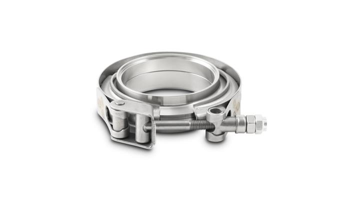
theres two basic types of header to collector v-band clamps for exhausts
this type requires that you weld two flanges on the two pipes (collector and exhaust)
theres an internal V-grove the forces the two surfaces firmly together
this type is far faster and simpler than a three bolt header flange
https://www.summitracing.com/parts/vpe-1490
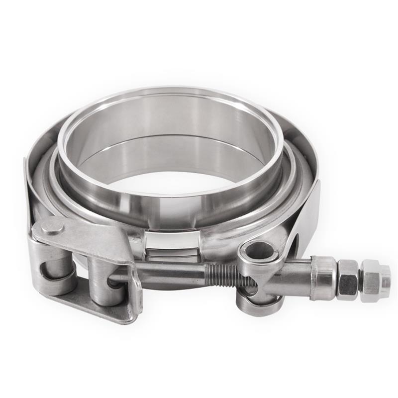
the other type requires that the exhaust pipe is a slip fit inside the collector and you cut short expansion slits in the collector,
this type clamps the external pipe firmly around the internal slip inside the collector exhaust,
this works if properly set up but has a habit of coming loose in some applications especially if theres lots of vibration or rough roads the clamped slip fit connection is not as secure as the type above
https://www.summitracing.com/parts/mio-mmclampvs25
most guys go the cheap route and buy and weld on 4 of the three bolt header flanges and use a replaceable gasket between the two welded in place header flanges, if you think it through you can weld the collector flange on the rear of the collector and the exhaust pipe flanges about 3/8" back along the exhaust pipe if you pre-fit the exhaust pipe inside the header collector, this allows a more secure seal once clamped
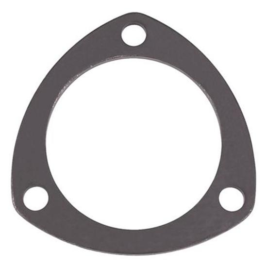
https://www.speedwaymotors.com/Steel-Exhaust-Collector-Ring-2-1-2-Inch,29244.html
yeah don't just weld the flanges, test fit carefully, before welding,
so the bolt holes on the flanges align and the exhaust stem and headers fir
correctly
this type requires that you weld two flanges on the two pipes (collector and exhaust)
theres an internal V-grove the forces the two surfaces firmly together
this type is far faster and simpler than a three bolt header flange
https://www.summitracing.com/parts/vpe-1490
the other type requires that the exhaust pipe is a slip fit inside the collector and you cut short expansion slits in the collector,
this type clamps the external pipe firmly around the internal slip inside the collector exhaust,
this works if properly set up but has a habit of coming loose in some applications especially if theres lots of vibration or rough roads the clamped slip fit connection is not as secure as the type above
https://www.summitracing.com/parts/mio-mmclampvs25
most guys go the cheap route and buy and weld on 4 of the three bolt header flanges and use a replaceable gasket between the two welded in place header flanges, if you think it through you can weld the collector flange on the rear of the collector and the exhaust pipe flanges about 3/8" back along the exhaust pipe if you pre-fit the exhaust pipe inside the header collector, this allows a more secure seal once clamped
https://www.speedwaymotors.com/Steel-Exhaust-Collector-Ring-2-1-2-Inch,29244.html
yeah don't just weld the flanges, test fit carefully, before welding,
so the bolt holes on the flanges align and the exhaust stem and headers fir
correctly
Last edited:
busterrm
solid fixture here in the forum
Well the 3 bolt flanges I am avoiding, they cause ground clearance issues! I am also going to set the collectors above the subframe rails. Standard store bought headers go about an inch below that level of the subframe, then the 3 hole flg causes it to be even lower. My plan is to eliminate that 1 inch below and the v band may be even or extend a little below the subframe!