Engine Balancing

jp75vette

New Member
Does anyone have tips on engine balancing?


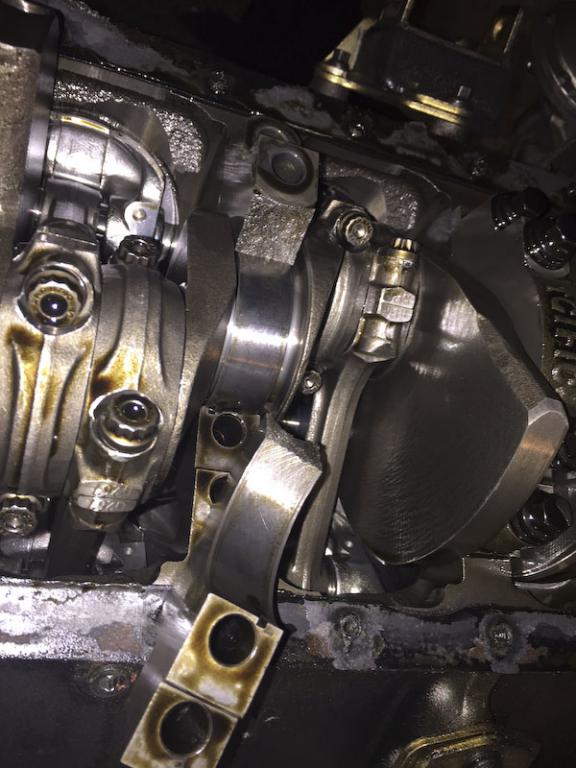
I bought an externally balanced 383 that ran fine in a 67 Chevelle with an automatic transmission. I had the new flywheel and clutch supposedly balanced to the flex plate that was in the Chevelle. I installed the 383 in my 1975 Corvette with a 4 speed BW ST-10 4 speed. I have vibrations at mid teens and 3300. From what I’ve read this is likely clutch/transmission related. I believe the main bearings are wearing as oil pressure seems to be dropping a bit.


My plan is to pull engine, take it apart and have all components balanced. The guy I have located will balance the piston/rod, crank, balancer and all the rotating elements. What tolerance should the balancing be done to?
 
precision balance jobs generally try to get the engine to be balance to within a 1/2--1 gram tolerance, naturally the more time it takes, and the more precise the work, the more it tends to cost
the only way your going to get a precise balance job is to have all the components weights and balance known and all the components matched in individual weight, first balanced individually, as each connecting rod big and small end weight needs to match, and each piston needs to match, then have all the bob weights on the crank match the weight the piston & rods weight as a complete assembly, the crank with its flywheel or flex- plate and damper need to be balanced as a rotating assembly .
I generally use and suggest use of scat 4340 forged cranks or occasionally the 9000 cast steel scat cranks for daily driver applications, SCAT, usually does a good job of carefully checking crank dimensions but its your job to check clearances , anytime you build an engine its the builders responsibility to verify clearances, and youll almost always find a rotating assembly needs to be balanced, obviously the crank manufacturer can,t dictate what rods, pistons,piston pins, rings, damper or flywheel are used so the crank counter weights won,t be perfectly balanced
its generally best to buy a complete matched rotating assembly, that includes rods,crank,pistons,rings,bearing damper and flywheel or flex plate. from a single source and ideally with MATCHED INTERNAL vs EXTERNAL BALANCED COMPONENTS
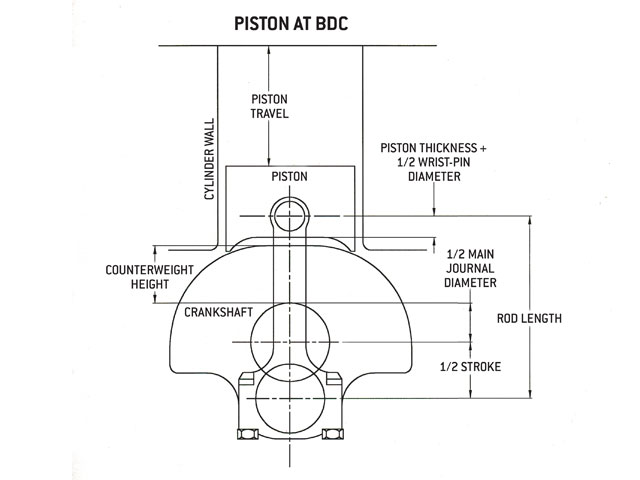
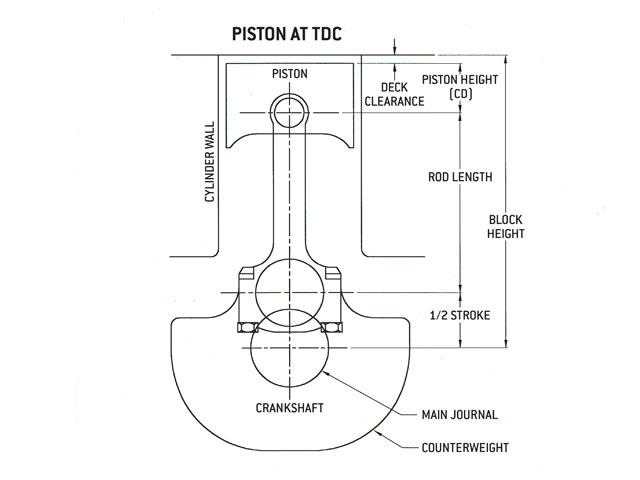
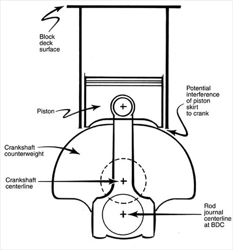
If your crank counter weights are the correct size and weight, and located on the crank in the correct location,they can be drilled to remove weight, and can be used to balance the rotating assembly with the counter weights on the crank shaft acting to counter balance the adjacent rods and pistions, if the counter weights are not large enough, mallory metal is added to crank counter weights because they are not large and heavy enough to compensate for the weight of the pistons and connecting rods, if the crank was designed to allow the counter weights to clear a piston skirt on a 5.7" connecting rod, the counter weights, are significantly smaller, than a crank designed for a 6" connecting rod and its very unlikely to have counter weights large enough to counter balance a 6" connecting rod assembly.use of center area counter weights on internally balanced crank assembly's tends to allow the other counter weights to be smaller and extend less distance out from the crank center line making clearancing the block easier
ENGINE BALANCING
http://garage.grumpysperformance.com/index.php?threads/engine-balancing.3900/

http://garage.grumpysperformance.co...s-one-really-over-looked-part.978/#post-79095
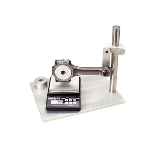
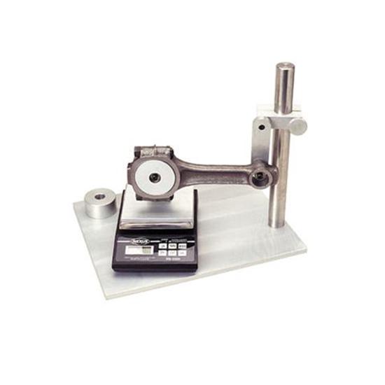
rodb1.jpg

http://www.angelfire.com/ca4/CorvAIRCRAFT/RodBalance.html

I posted a message to the CorvAIRCRAFT e-mail list, and I shortly had my answer.


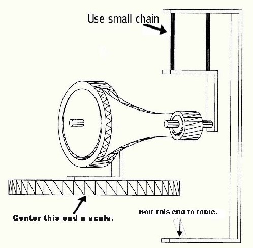
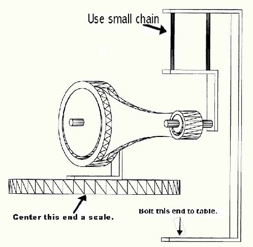
rodb2.jpg


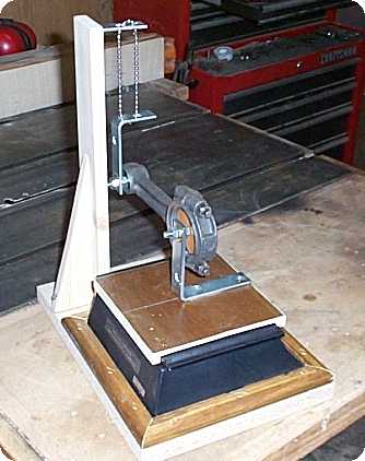
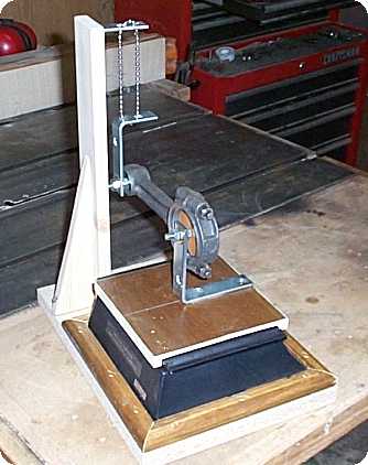
Don McGehee sent me a private e-mail with this attached drawing of a jig which was drawn from memory of one he saw in a hot rod engine shop.

rodb3.jpg


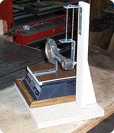
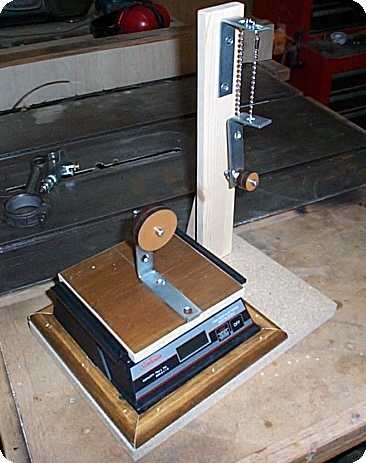
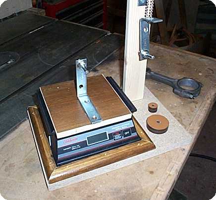
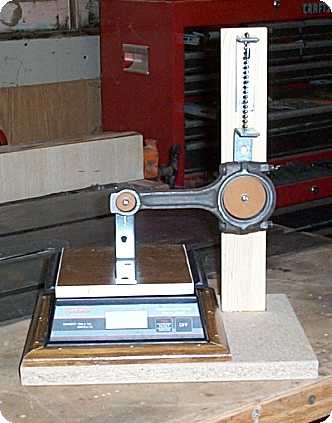
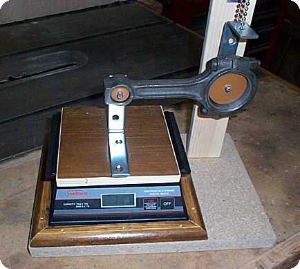
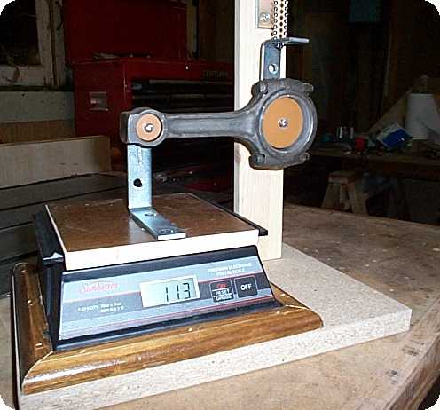
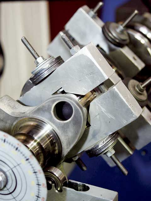
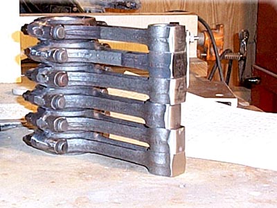
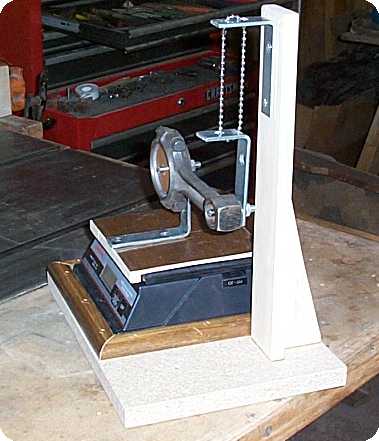
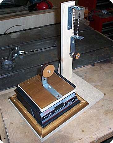
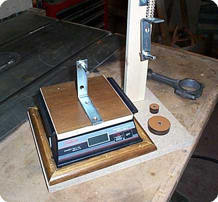
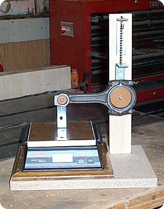
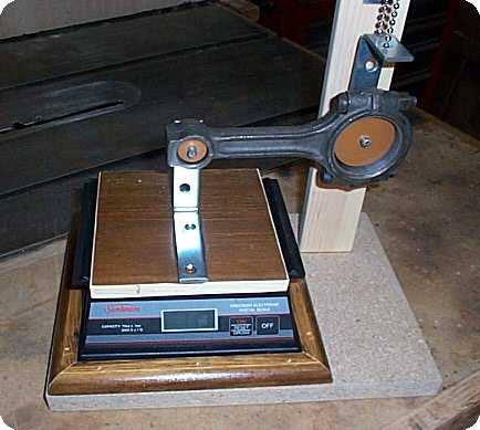
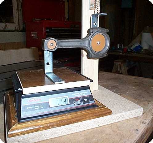
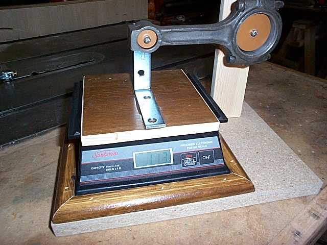
From his drawing, I made this jig.

I turned 2 phenolic disks which slide freely over a shaft, which lowers friction and allows me to change the disks from one shaft to the other, for balancing each rod end.

Although the centers of the shafts are the correct distance apart, the chain all but eliminates any unwanted side loads.

I've been able to remove and replace the connecting rod on this jig, and if it's not exactly the same weight when I make the change, it's only 1g difference.


rodb4.jpg


rodb5.jpg
rodb6.jpg


rodb7.jpg
rodb8.jpg


rodb9.jpg


Dcp01022.jpg


One good thing I've found out from this exercise is that the stock connecting rods are very close anyhow. From my heaviest to my lightest, there's only a 7g difference.

pistonatbdc.jpg

pistonat%20tdc.jpg


only the balance shop can determine whats required after inspecting the components youve selected, in some cases youll be far better off to buy a new crank or a complete rotating assembly rather than to try to patch together random selected components, but like I stated discus this with the shop balancing your engine.
some times you can select lighter piston pins, or pistons but keep in mind random parts are un-likey to balance as a matched set, and cap screw connecting rods with 7/16" rod bolts can be 200% stronger and yet have more clearance than stock connecting rods
ebm4.jpg

WHATS THE DIFFERENCE BETWEEN INTERNAL AND EXTERNAL BALANCE
good question, so let me show you a easy explanation
with an
internally balanced crank each counter weight compensates for the loads directly adjacent from it, AND THE FLYWHEEL AND DAMPER ARE INDIVIDUALLY BALLANCED
on
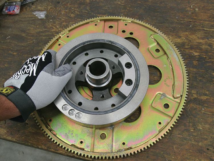
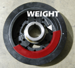
an externally balanced crank the flywheel and dampers at the ends of the crank
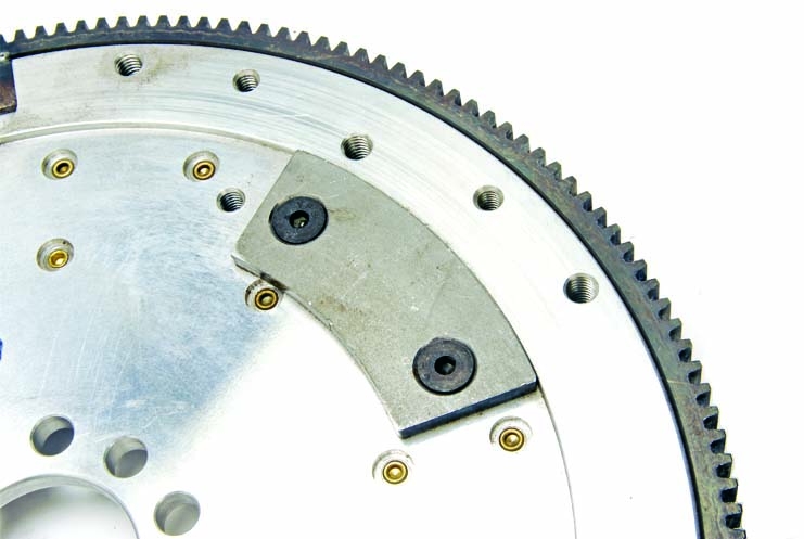
ARE WEIGHTED , OFF CENTER TOO COMPENSATE FOR THE LACK OF COUNTER WEIGHT MASS TOO BALANCE THE COMPLETE ROTATING ASSEMBLY,

so the total imbalance is averaged and a weight is placed to compensate for that average, if both cranks were placed on roller bearings and spun both would rotate fairly freely
With "internally balanced" engines, the counterweights themselves handle the job of offsetting the reciprocating mass of the pistons and rods. "Externally balanced" engines, on the other hand, have additional counterweights on the flywheel and/or harmonic damper to assist the crankshaft in maintaining balance. Some engines have to be externally balanced because there is not enough clearance inside the crankcase to handle counterweights of sufficient size to balance the engine. This is true of engines with longer strokes and/or large displacements
now for a simple explanation
grab a single strand of uncooked spaghetti, and draw a line along one edge with a black marker
an internally balanced engine has stress loads compensated adjacent to the stress location, so try rolling the strand of spaghetti back and forth from two closely spaced locations between your fingers, notice the marked edge stays strait,now an externally balanced engine is balanced from the ends of the crank, so grab both ends of the strand between your fingers in the same direction at the same time,then roll with one end but resist or add drag with the other set of fingers, notice the line on the edge starts to spiral back and forth as you change direction on the loads induced, thats exactly whats going on over the length of the crank on an externally balanced crank. its flexing a good deal more and loads induced stress the whole length.
crankshaft.jpg.gif

WATCH VIDEO

cypre.jpg


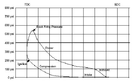
there can easily be 600- 700 psi of pressure exerted on a piston in a high compression performance engine as the engines reaches max cylinder pressure, theres over 12.5 square inches of piston surface area in a 383 engine so thats easily over 8500 pounds of pressure being exerted on each crank journal and bearing several times a second, this causes a crankshaft to flex , the piston and connecting rod also weigh a significant amount a can induce significant inertial loads as they change directions at higher rpms, loads can easily exceed 10,000 lbs in combined stress on a crank journal 50 plus times a second at 7000rpms
crankB.gif

http://rlengines.com/Web_Pages/Cranksha ... ncing.html

keep in mind if your building a common 383 sbc as an example the crankshaft designed for 5.7" rods will have slightly smaller counter weights than a similar crank designed for the slightly heavier 6" rods so try hard to get the lighter weight pistons and specify the lighter than standard tool steel tapered piston pins that cost a bit more because the extra cost of the pins is usually more than off set with the slightly reduced cost incurred during having the assembly balanced, because Malory metal slugs are rather expensive.
counter weights designed for 6" rods will not generally clear piston skirts on a combo using 5.7" connecting rods and a crank with counter weights designed to clear 5.7" rods won,t have enough weight to balance 6" connecting rods without mallory metal added to the counter weights.
this is one good reason to buy a MATCHED rotating assembly as a package deal from a well known and trusted supplier like SCAT,CROWER,LUNATI and specify internal or external balance and the correct rod length, piston bore size and steel alloy ETC.

watch video

READ THE RELATED LINKED INFO
http://www.hotrod.com/articles/ccrp-0803-engine-balancing/
viewtopic.php?f=53&t=204

http://www.enginebuildermag.com/2009/05/understanding-crankshaft-balancing/

http://www.mime.eng.utoledo.edu/faculty ... 1-0258.pdf

http://www.dougherbert.com/

http://www.scatcrankshafts.com/Default.asp

http://www.speedomotive.com/

viewtopic.php?f=53&t=141&p=5391&hilit=internal+external#p5391

http://www.adperformance.com/index.php? ... x&cPath=71

http://www.crower.com/products/crankshafts.html

http://www.maintenanceresources.com/ref ... alance.htm

http://www.circletrack.com/enginetech/c ... rminology/

viewtopic.php?f=53&t=141&p=175#p175

http://www.eaglerod.com/

http://www.lunatipower.com/ProductGroup ... 186&cid=18

and several other companys supply balanced kits


What is Balancing?
Balancing is the action of matching the weights of the reciprocating parts of the engine. These parts include, but are not limited to:
Pistons and Piston Pins
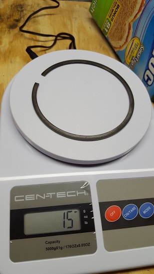
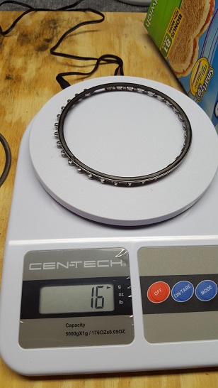
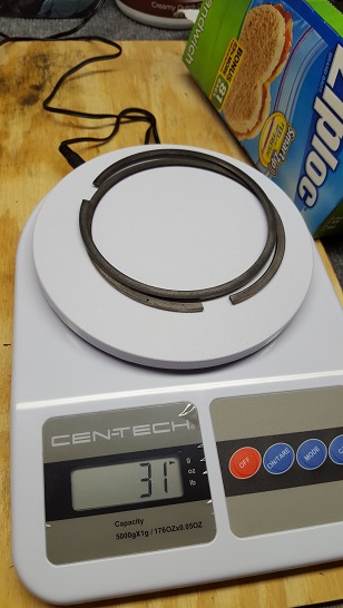
Piston Rings
Rod Bearings
Connecting Rods (large and small ends, need to be weight matched)
Crankshaft
Damper (harmonic balancer)
Flywheel/Flex Plate
Pressure Plate/Clutch (frequently over looked)
Also, an "Estimated" Weight of Oil is part of the calculations

bobweight.jpg

once you get the assembly balanced ask for the SPECS so any future replacement parts can be easily matched
example if your piston weights 589 grams you need to know that.
once balanced your clutch pressure plate should have a obvious index mark that matches the identical mark on the flywheel so the two components are always assembled together the same way as a unit. SOME SHOPS stamp a BL some shops JUST drill or punch a small DOT, on both the pressure plate and flywheel ,so be aware and look for and match components indexed correctly, and MENTION that you WANT the pressure plate balanced with the flywheel, theres a good chance that if you don,t mention and insist on getting it done that its ignored and this can be a source of vibration if not done(one more reason to get a good SFI rated blow proof pressure plate and BILLET fly wheel, and use a LAKEWOOD blow proof bell housing)


read thru these links

viewtopic.php?f=53&t=259&p=314#p314

viewtopic.php?f=53&t=141&p=175&hilit=+balancing#p175

you obviously need a correctly installed bell housing that correctly centers the transmission input shaft with the crank center-line or that can cause problems

viewtopic.php?f=71&t=584&p=757&hilit=lakewood#p757

viewtopic.php?f=71&t=2596&p=6689&hilit=+pilot+grease#p6689

balgraph.jpg
 
Last edited by a moderator:
Crank Journal: Installation Procedures For Placing Heavy Metal Into Crankshaft Counterweights
119834jpg.jpg

mallory_heavy_metal_slugs.jpg

9227171_n.jpg

OBVIOUSLY a machine shop doing balancing work on a rotating assembly's , and adding mallory metal slugs to counter weights,on the crank must do quality work or problems with durability usually result that get damn expensive or dangerous


119834ajpg.jpg

119834bjpg.jpg

119834cjpg.jpg

counterweightsa.jpg

external_engine_balance.jpg

external balance weights
flexplate_front_and_rear.jpg

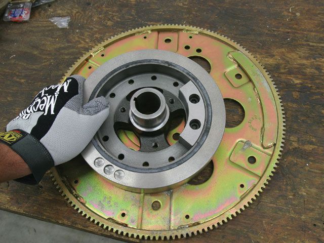
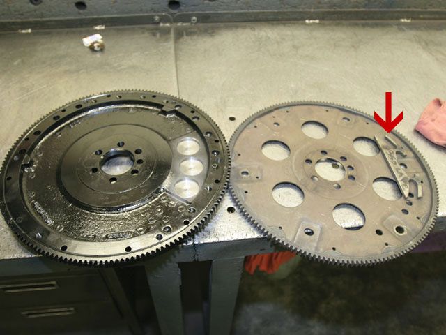
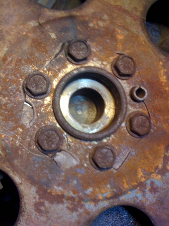
IF YOUR GOING TO PUT THE TIME AND EFFORT INT A DECENT ENGINE BUY AN SFI CERTIFIED FLEX-PLATE< STOCK ONES ARE SO THIN THEY CRACK CONSTANTLY IF SUBJECTED TO HIGHER STRESS
3571.jpg


external balance weights
By Duane Boes

viewtopic.php?f=53&t=5155

http://www.enginebuildermag.com/201...ing-assemblies-in-the-modern-day-engine-shop/


We’re all familiar with the old saying, "We learn from our mistakes." Recently, I was able to learn from someone else’s misfortune. I make plenty of mistakes of my own, so taking a lesson without the expense was a welcome change.

Installation procedures for placing heavy metal into crankshaft counterweights is a simple procedure to explain and implement. If things are done right, there is little to fear from a shaft with metal placed in the counterweights.

However, when a heavy metal slug does begin to move, things can get ugly fast. Consequently, proper installation steps to prevent a slug’s movement are important to know and understand.

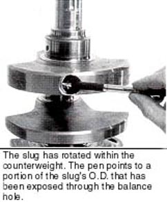
Counterweights are subjected to fairly simple forces. Their vibrations, on the other hand, are quite complex. These vibrations can create strange reactions in a slug placed into a counterweight. The photo below is an example of something unpredictable happening.

Notice how the slug has rotated within the counterweight. The pen in the photo points out a portion of the slug’s O.D. that has been exposed through the balance hole. This can only happen if the heavy metal begins to turn.

You would expect a slug to slide one way or the other should it begin to lose its press fit. But to see it rotate is completely unexpected. Interestingly, while this piece of heavy metal rotated roughly .200", it shifted very little. For me to try and explain these vibrations would be a case of trying to explain more than I really understand.

Diameters are "Job #1" when it comes to installing heavy metal. The best insurance against a costly problem starts with the press or interference fit between the heavy metal and the hole it’s placed in. Slugs of 1" diameter require between .002" to .004" interference. To maximize the holding power of this interference fit, both the O.D. of the slug and the I.D. of the hole need to be as round as possible.

Even with every effort possible being made, the slug and the hole will not match perfectly. To overcome this variable I recommend using Loctite 640. I have tested the advantage of using this product several times; the results have been consistent.

Without the use of such a bonding agent a 1" diameter slug installed with a .004" press fit will require nearly seven tons of force to be placed upon it before shifting occurs. With the bonding material, the amount of force needed to shift the slug jumps to roughly 15 tons. Once the slug has been broken free, the force required for continued movement drops to seven tons.

In consideration of the oily environment and operating temperatures, Loctite Corp. recommends its 640 compound. The product can be used very sparingly and still be effective. Anyone who is not comfortable with their press fit, and is staking the O.D. of the slug, should seriously consider using some type of bonding agent.

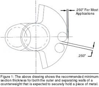
The problem shown in the photo to the left is the direct result of poorly planned placement and drilling. A slug’s placement is nearly as important as its fit. Figure 1 below is a drawing of recommended minimum section thickness for both the outer and separating walls of a counterweight that is expected to securely hold a piece of metal.

An adequate amount of material must be provided between the slug’s O.D. and the circumference of the counterweight. You can visualize that in the case of a section that is too thin; the counterweight’s material will stretch either during the installation or while in operation due to the centrifugal force. In either event the press fit is reduced, opening the door for unwanted movement.

The same type of deformation can occur at the separating wall. In situations where two slugs are adjacent, the wall is holding one-half of each slug. In this system, the separating wall must withstand a load equal to the total weight of one slug at maximum rpm.

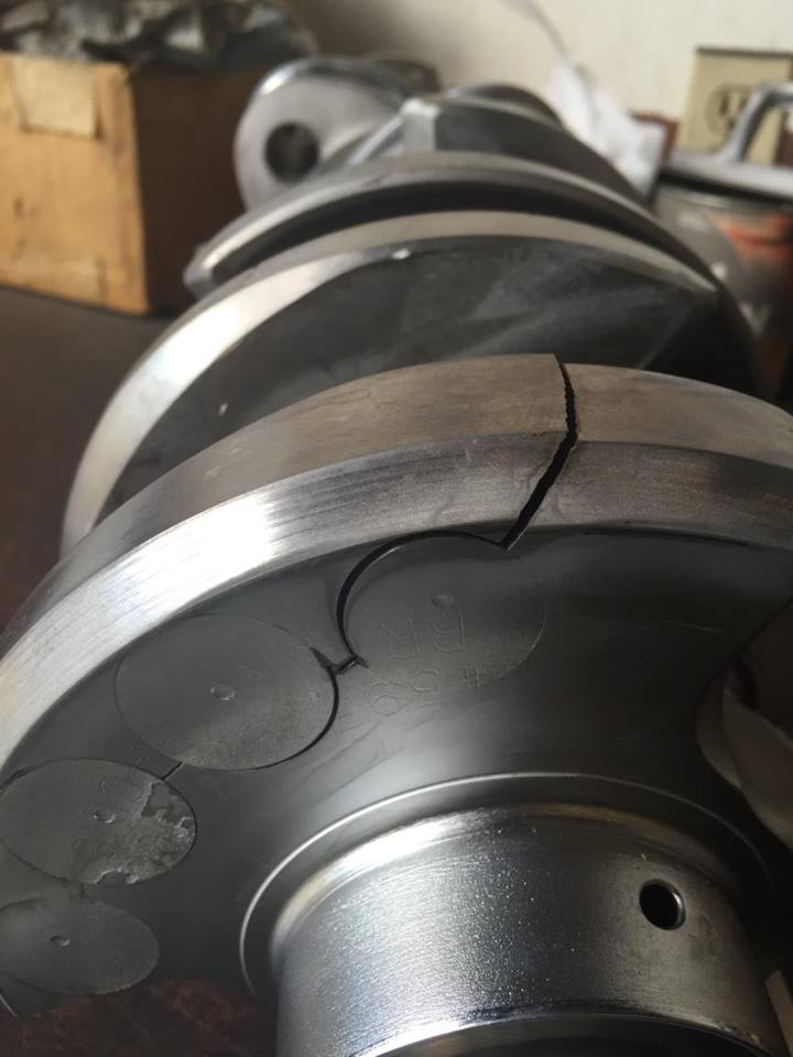
Drilling locations
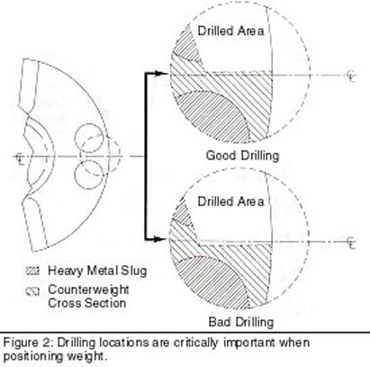
Drilling locations are the next point of concern. The root cause of the problem in the photo stems from a poorly planned drilling into the counterweight. The wall thickness dimensions detailed in Figure 1 may seem a little extreme. Unfortunately, it’s not uncommon to find yourself in a situation where the weight to be removed will fall directly on a series of slugs. In these instances the extra material will be good insurance.

Figure 2 illustrates the effect that drilling has on the counterweight material responsible for holding the heavy metal in place. Attention has to be given to these drill locations. The object being to remove weight without significantly weakening the interference fit between the slug and its surrounding counterweight material. This can be accomplished by limiting drilling to the locations detailed in Figure 2.

In summarizing heavy metal installation, there are four important points to remember. First, make sure your press fit is adequate and that the hole and slug are round as possible. Second, use some type of bonding fluid to fill voids, ensuring a solid footing. Third, make sure the metal is placed into the counterweight in a manner that will maintain a good press fit. Fourth, and last, be careful not to drill out the counterweight material responsible for holding the slug.

A number of engine rebuilders work on modified big block engines. Most of these engines are balanced externally from the factory. In OEM applications external balancing presents few problems. This situation, however, changes as rpm and compression ratios are increased.

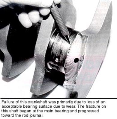
In an externally balanced system number 2 and 4 main bearing loads are significantly increased. Externally balanced crankshafts that have broken as a result of a fracture starting at the main bearing side of the overlap are common. Most of these broken cranks also exhibit signs of main bearing wear particularly on numbers 2 and 4. This is the result of higher loads placed on those mains.

The simplest cure for this on higher horsepower engines is an internal balance. In cases where this is not an option, the crankshaft should be heat-treated. By placing a hard wear layer on the journal, bearing life is significantly increased.

The photo below is a close-up of a broken big block Chevy crankshaft. The fracture on this shaft began at the main bearing and progressed toward the rod journal. The photo also shows heat discoloration on the main bearing. The discoloration is uniform around the journal circumference.

This type of heat is consistent with a bearing that is running in distress. Heat generated on a broken shaft is not uniform around the journal; the heat from this type of failure is localized in the areas of interference as the shaft is wedged into the block.

On this crank, the primary failure was the loss of an acceptable bearing surface due to wear. Clearances opened, oil left the journal at a rapid rate taking with it the film barrier, resulting in the generated heat.

A customer’s perception of the problem will usually begin and end with the failed component. For the rebuilder, however, being able to explain why the component failed will always require a much deeper understanding.
 
Last edited by a moderator:
I was just going to post why you don't hear about clutch/pressure plate being included in the balance conversation. I see it should be!

Also, new ATI's they state in the instructions DO NOT include in the balance because they take a set.
 
balkz4a.jpg

Understanding Crankshaft Balancing
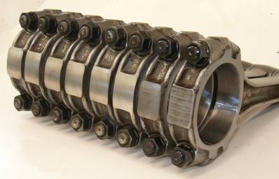
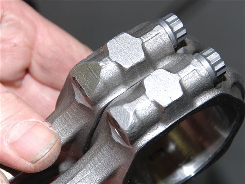
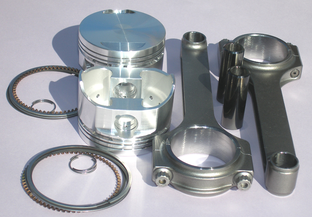
generally the small and large ends of each rod is weighted and the heavier rods ends are belt sanded on the ends until all connecting rods in a set weight the same on both ends, after the rod caps are numbered to prevent parts beings swapped between rods, the piston pads under the pin boss are milled to get the pistons to the same weight and the cranks counter weights are milled, drilled or have weights welded into drilled holes to add weight[/b]
baln1.jpg

baln2.jpg

baln3.jpg

baln4.jpg

baln5.jpg

baln6.jpg

baln7.jpg

baln8.jpg

Mallory metal
From Wikipedia, the free encyclopedia
Mallory metal is proprietary name[1] for an alloy of tungsten, with other metallic elements added to improve machining.


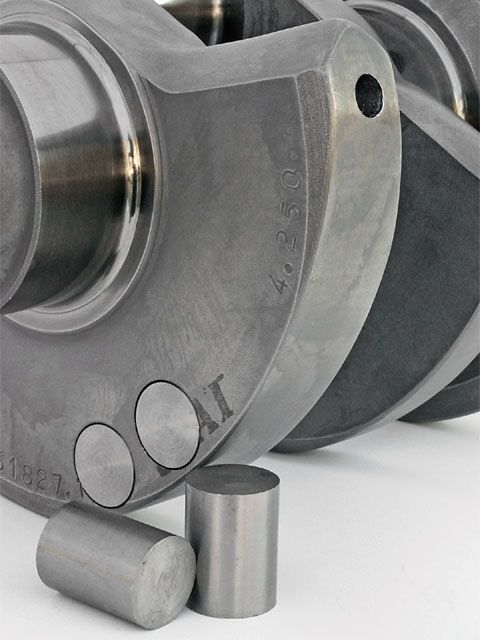
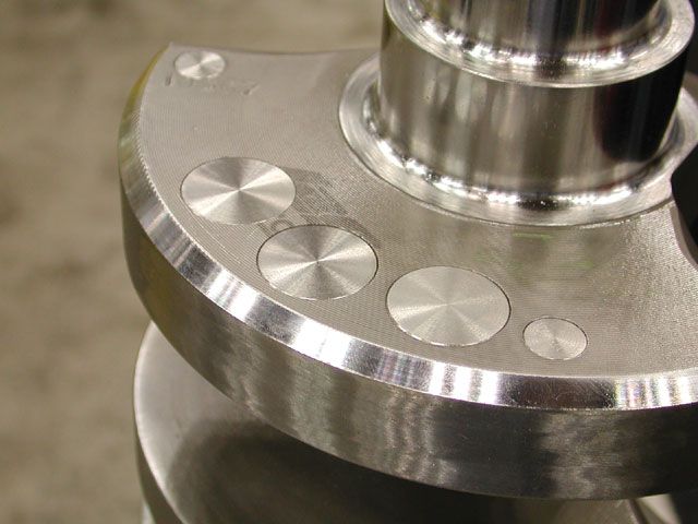
Its primary use is as a balance weight which is added to the crankshaft of an automotive engine, where the existing counterweight is not large enough to compensate for the weight of the reciprocating and rotating components attached to the crankshaft's connecting rod journals. Rather than add to the counterweight by welding or fabrication, holes are drilled in structurally safe positions in the counterweights, and "slugs" (cylindrical dowels) of Mallory metal are inserted and fastened securely.

http://www.crossmembers.com/shop/fly-wheels-c-18.html


http://www.hotrod.com/articles/ctrp-0504-engine-balancing-tech-terminology/

http://www.caranddriver.com/features/the-physics-of-engine-cylinder-bank-angles-feature

http://bangshift.com/bangshift1320/...equires-serious-research-and-experimentation/

http://www.cwtindustries.com/whybalance.htm


The difference in density between the replacement Mallory metal and the original steel is about 2:1, so the counterweight is heavier without changing its shape or size.
9227171_n.jpg

OBVIOUSLY a machine shop doing balancing work on a rotating assembly's , and adding mallory metal slugs to counter weights,on the crank must do quality work or problems with durability usually result that get damn expensive or dangerous


baln9.jpg

baln10a.jpg

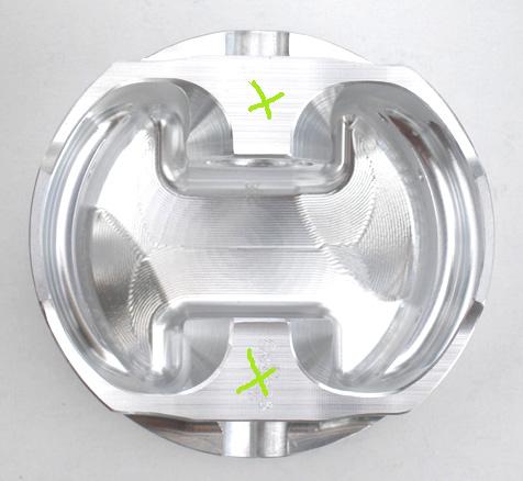
the areas with green Xs are milled to balance piston weight
baln11.jpg

obviously to find the correct weights every components weight should be accurately weighted and recorded and all cylinders weight equalized
balkz1a.jpg

balkz2a.jpg

balkz3a.jpg

balkz4a.jpg

balkz5a.jpg

balkz6a.jpg

balkz7a.jpg

balkz8a.jpg

baln12.jpg

if the engines EXTERNALLY BALANCED theres off center weights added to the balancer and flex plate or fly wheel to compensate for the lack of extended counter weights on the crank shaft

Since different rods and different pistons are different weights, it is impossible to make a crankshaft that is balanced "right out of the box" for any rod and piston combination. All crankshafts must be balanced to your specific rod and piston combination.

viewtopic.php?f=53&t=1168

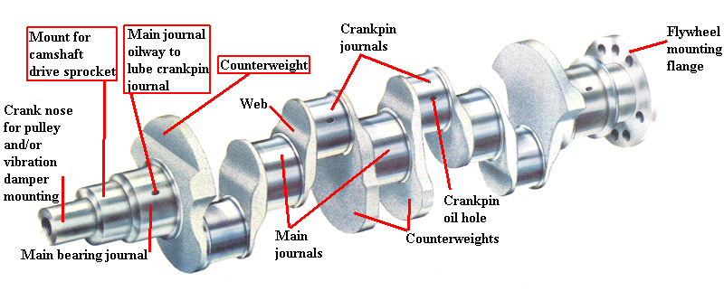
The first step in understanding crankshaft balancing is to understand the purpose of the counterweights. The counterweights are designed to offset the weight of the rod and pistons. You have the weight of the crankshaft and the pistons and rods. At any point in the assembly's rotation, the sum of all of the forces are roughly equal to zero.

If the counterweights are the correct weight to offset the weight of the rods and pistons, the crankshaft is balanced. If the counterweights are too heavy, material must be removed by drilling or milling the counterweights. If the counterweights are too light, weight must be added to the counterweights. This is usually done by drilling a hole in the counterweight and filling the hole with "heavy metal" or "mallory". This filler metal is denser and heaver than steel (but not stonger) so the weight of the counterweight will increase as a result.
heres the catalog
http://www.scatcrankshafts.com/downloads/14scat_catalog_10-13.pdf

http://www.scatcrankshafts.com/rotating-assemblies/rotating-assembly-product-search/
Phone: 310 370 5501
Internal Balance & External Balance

When the counterweights alone can be made to balance the crankshaft, the crank is said to be "internally balanced". If the counterweights are too light by themselves to balance the crankshaft and more weight is needed, an "external balance" can be used. This involves a harmonic dampener or flywheel that has a weight on it in the same position as the counterweight that effectively "adds" to the weight of the counterweight on the crankshaft.
use of center area counter weights on internally balanced crank assembly's tends to allow the other counter weights to be smaller and extend less distance out from the crank center line making clearancing the block easier

Since the harmonic dampener (front) or flywheel (rear) play a part in the balancing of the assembly, they must be installed on the crankshaft when it is balanced. This is unlike an internal balance configuration where the harmonic dampener or flywheel do not contribute to the balance of the crankshaft and are not required to be installed when the crankshaft if balanced. Both methods are used from the manufacturer.

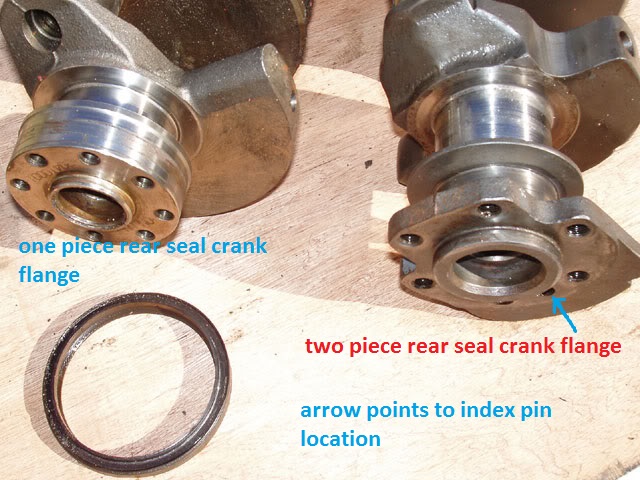
An example of some factory internally balanced engines are Chevy 305 and 350 (2 piece rear seal only!), Chevy 396/427, GM LS-series, and Ford "modular" 4.6. Some examples of factory externally balanced engines are Chevy 400 and 454, Ford 302 and 351W.

Some engines are a combination of both being internally balanced in the front and externally balanced in the rear. The most common example of this is the Chevy 350 (1 piece rear seal) including LT1. Regradless of how an engine is balanced from the factory any balancing method is acceptable as long as the required harmonic dampener and/or flywheel is available.

"Is my crank balanced?"

Since different rods and different pistons are different weights, it is impossible to make a crankshaft that is balanced "right out of the box" for any rod and piston combination. All crankshafts must be balanced to your specific rod and piston combination. When a crankshaft is listed as "internal balance" or "external balance" this is stating how this crank is intended to be balanced. It can be balanced otherwise, but it is much more difficult to do so.

Eagle crankshafts, for example, are listed with a "target bobweight". This is an approximation (+/-2%) of the bobweight the crankshaft is roughly "out of the box". Because of the tolerance (+/-2%) the crankshaft cannot be considered balanced. For instance, for a crankshaft listed as having a 1800 target bobweight.

The actual range of bobweights one of those cranks might have is from 1764 (1800-2%) to 1836 (1800 +2%). It might even be at the high end of that range on one end and the low end of that range on the other! This is not usually a problem because Eagle crankshafts are designed to have a target bobweight higher than most typical rod and piston combinations. Therefore, in most cases you will only need to remove material to balance the crankshaft instead of adding material.

The main benefit of the target bobweight is to help the machine shop know what to expect before balancing so that a more accurate price estimate can be made. Eagle will balance a new crankshaft at the time of purchase. You will need to provide the bobweight you want it balanced to, which must be below the target bobweight listed for the crankshaft.

Bobweight

When a crankshaft is balanced, the actual rods and pistons cannot be used in the balancing machine, so they must be simulated. This simulated weight is called the "bobweight". Once the bobweight is calculated, weights are bolted onto the rod journals to simulate the weight of the rods and pistons during the balancing process. Due to the configuration of a "V" type engine, just adding all the weights together does not work.

There are also some dynamic considerations to be made when balancing the crankshaft. Explaining those is beyond the scope of this discussion. If you want to study those topics further, contact a crankshaft balancing machine manufacturer and they can go into greater detail.

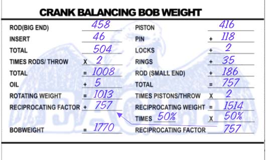
To calculate the bobweight of a particular assembly, the following formula and balance card is used:

For example, let's say we are balancing a Chevy 383 with the following component weights:

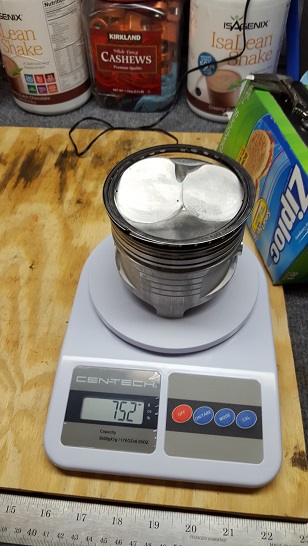
Piston 416g
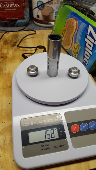
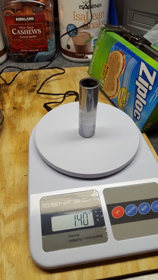
Pin 118g
Locks 2g
Rings 35g
Rod big end 458g
Rod smal end 186g
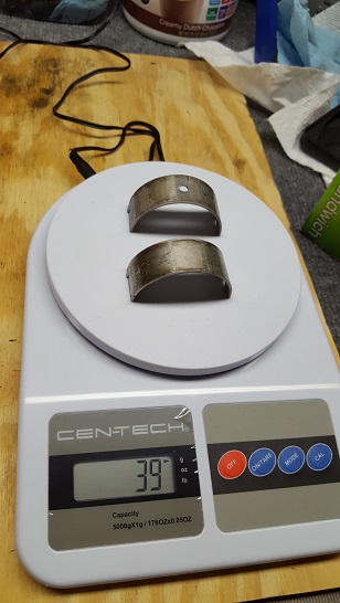
Bearings 46g

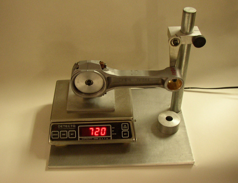
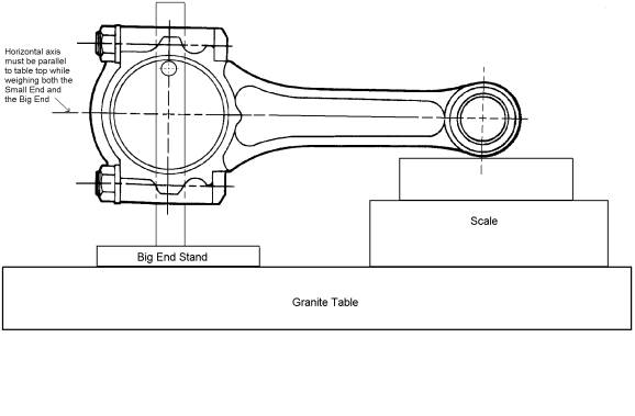
The rod weight is seperated into "big end" and "small end". This is necessary because the small end has a reciprocationg (back and forth) motion and the "big end" has a rotating motion. This split weight is figured on a special scale fixture that supports one end of the rod while weighing the other end.

There are several things to note about this calculation. The "oil" value used on the left side of the calculation is an approximation of the weight of residual oil "hanging around" on the assembly. The number used here is a matter of preference. There is no solid "rule of thumb" for this. Eagle uses 5g for small block assemblies and 15g for big block assemblies. Since it is impossible to accurately represent this value, it is just an estimate. The actual amount of oil can change constantly and can even be different from cylinder to cylinder! We have found through experience that the numbers we use estimate this property well.

The second thing to note is the 50% value used for the reciprocating factor. This number deals with the geometry of the engine itself. A 90 degree bank angle "V" engine will use 50% here. A V6 or a narrow or wide bank angle "V" engine will use a different value (again, consult the balancer manufacturer). Some engine builders will perform what is call "underbalancing" or "overbalancing". They will use slightly differnet values here such as 48% or 52%. This is done to help compensate for dynamic effects at extremely high or extremely low rpm operation (again, beyond the scope of this discussion). Eagle uses 50% because this value is required for almost all common street or racing engines.

Balanced Rotating Assemblies

Most Eagle rotating assemblies are sold unbalanced so that engine builders can balance it however they wish. Eagle (and other manufacturers) do offer fully balanced assemblies balanced. But it must be ordered specifically as a balanced assembly. Part numbers for balanced assemblies will begin with the letter B. For instance, if you want assembly part number 12006 balanced and in +.030" bore size, you would order assembly number B12006-030.

All Eagle forged 4340 steel crankshafts are designed for internal balance. An internally balanced kit will not include a harmonic dampener or flywheel because they are not required for balancing – use whatever brand you like. Externally balanced kits will include a harmonic dampener and/or flexplate as needed. If a harmonic dampener and flexplate is provided, it will be an O.E. style replacement, not SFI approved. If you’re building a high horsepower engine, internal balance is preferred. Internal balance is better for longevity of parts and fatigue life.

If your assembling a EXTERNALLY BALANCED 383 or 400 based engine,you'll need externally balanced flex-plate and damper components, obviously its best to have all components used balanced as a unit if possible

http://www.summitracing.com/parts/TFS-19001/

damper
http://static.summitracing.com/global/images/instructions/tfs-19000-01-02-03 trickflow instructions.pdf
damper install instructions

there are 153 and 168 tooth flex plates (12.8" and 14.1")and flywheels
youll need to get one that matches and is also externally balanced
http://forum.grumpysperformance.com/viewtopic.php?f=53&t=259&p=314#p314
exbal.jpg

examplebob.jpg


– Technical Tip courtesy of Eagle Products (http://www.eaglerod.com)


I've seen a great many machine shops who either just don,t give a rats A$$ or they are CLUELESS INCOMPETENTS
you can't assume anything you paid for was done correctly,
until

YOU VERIFY IT PERSONALLY (AND YES THAT REQUIRES PRECISION MEASURING AND EFFORT)

in either case this forces a decent engine builder to verify all the work was properly done

http://garage.grumpysperformance.co...-the-rabbit-hole-with-alice.10933/#post-66925


a day or so spent in careful research & reading can save you hundreds of dollars and months of wasted work

http://garage.grumpysperformance.com/index.php?threads/precision-measuring-tools.1390/

http://garage.grumpysperformance.com/index.php?threads/piston-to-bore-clearance.4630/

http://garage.grumpysperformance.co...tion-of-crank-durring-short-blk-assembly.852/

http://garage.grumpysperformance.co...g-and-installing-connecting-rods-pistons.247/

http://garage.grumpysperformance.com/index.php?threads/rotating-assembly-bearings.9527/

http://garage.grumpysperformance.co...oven-facts-if-your-in-doubt.13051/#post-69824

http://garage.grumpysperformance.com/index.php?threads/assembly-lube-summary.6352/

http://garage.grumpysperformance.com/index.php?threads/maximizing-piston-to-bore-ring-seal.3897/

http://garage.grumpysperformance.co...ng-and-basic-piston-ring-info-youll-need.509/
[/quote]
 
Last edited by a moderator:

For those people that want to calculate the BOB WEIGHT, there is a calculator in the " spread sheets and engine related forms"
section, along with many other calculators.

Here is a link to the spread sheet section:
viewforum.php?f=99

Here is a link directly to the calculator:
viewtopic.php?f=99&t=3447

This is what the main page looks like.


Attachments

  • BobWeightCalculations02.jpg
    BobWeightCalculations02.jpg
    88.7 KB · Views: 1,163
Racing Rotating Assemblies: Cranks, Rods and Pistons
http://jsmotorsport.com/technical_rodspistons.asp

onesealvstwo.jpg

damppic1.jpg

damppic2.jpg

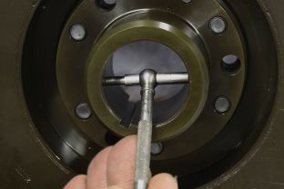
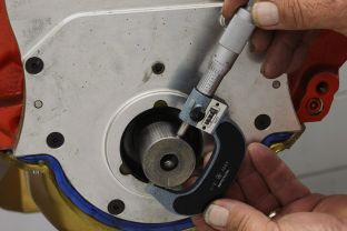
Measure the crank-snout diameter with a micrometer (above left). Ours measured 1.600 inch, which is right on spec. Then use a dial-bore gauge to determine the inside diameter of the Fluidampr damper (below). Ours came in 1.599-inch, resulting in a .001-inch interference fit. This is the right amount of clearance to provide a good snug fit on the crankshaft, but still be able to install and remove without difficulty. Another method of measuring the damper hub ID of your is with a snap gauge (above right). After setting the gauge, the micrometer is used to to determine the final measurement. In this case, the same measurement as the dial bore gage was reached.
http://www.enginebuildermag.com/Article ... stons.aspx

The crankshaft, pistons and connecting rods inside an engine convert thermal energy in the cylinders into rotational energy that produces usable horsepower and torque at the flywheel.

By Larry Carley

Larry Carley

Building a performance engine requires assembling the optimum mix of rotating components that are compatible with the block and heads, properly matched with each other, and balanced to precise tolerances.

The easiest way to get the right combination of parts is to buy a complete rotating assembly from a supplier who offers such kits. Most suppliers offer a wide range of rotating assemblies for street, strip or circle track applications. A complete kit takes the guesswork out of matching the rod lengths and piston configurations with a stroker crank, or matching piston and rod weights with the counterweights on a crank (particularly lightweight cranks). For an extra fee, many suppliers will balance their rotating assemblies for you, which they say reduces the risk of balancing errors that sometimes occur when cranks are incorrectly balanced or over-drilled to correct a heavy spot.

Though crankshaft, connecting rod and piston kits are often marketed directly to racers who want to assemble their own engines in their garage, kits are certainly an option for professional engine builders who are working within time and/or budget restraints, or who lack their own balancing equipment. Buying a complete rotating assembly (which may also include bearings and piston rings) versus sourcing the crank, rods, pistons, rings and bearings from different suppliers reduces the risk of mismatched parts that can cause assembly problems, durability and balance problems. It’s one-stop shopping – and only one supplier to deal with if there are any problems.

For example, it makes no sense to spend big bucks on a lightweight crankshaft, then mate it with a set of relatively heavy connecting rods and pistons. The advantages of using a lightweight crank (faster throttle response and more rapid rpm changes) would be reduced because of the heavy pistons and rods. A lightweight crank must be used with lighter pistons and rods to take full advantage of the reduced rotating mass of the crank.

Mismatched parts can also create balance problems if the mass of the counterweights on a crank don’t closely match the reciprocating mass of the pistons and rods. A lightweight crank has smaller counterweights because it is designed for lighter pistons and rods. If you try to use pistons and rods that are too heavy for the crank, balancing the crank will require adding slugs of expensive Mallory (heavy metal) to offset the added mass. That adds weight back to the crank and undermines the advantages of buying a lightweight crankshaft to reduce weight.

It’s a Balancing Act
A precision balance job is absolutely essential for any high revving performance engine, but it’s also recommended for street performance engines, too. Balancing reduces loads and vibrations that stress metal and can eventually lead to component failure. What’s more, a smoother running engine is a more powerful engine. Less energy is wasted by the crank as it thrashes around in its bearings, which translates into a more usable power at the flywheel.

If a rotating assembly is put together without balancing all of the individual components, it’s impossible to say whether or not the assembly will be within acceptable tolerances for balance. The counterweights on stock cranks are sized for stock connecting rods and pistons. Replacing the stock rods and/or pistons with aftermarket performance parts will likely upset the balance because the new parts will usually have a different weight (usually lighter, but not always).

A difference of a few grams may not seem like much, but it all adds up. A few grams here, a few grams there, and pretty soon you’ve created an imbalance that can produce noticeable vibrations and harmonics at various engine speeds. Imbalance usually gets worse the higher the engine revs due to centripetal forces that multiply exponentially with rpm. Double the rpm and you quadruple the force of the imbalance.

Many crankshaft suppliers publish “target bobweight” specifications for their cranks. This allows engine builders to choose rods and pistons that more closely match the design bobweight, or to estimate how much effort it will take to balance the crank if the bobweight of the rods and pistons vary significantly from the target bobweight.

The counterweights on the crankshaft are supposed to offset the reciprocating and rotating mass of the pistons, rings, wrist pins, rods and bearings. The mass of each counterweight should equal 50 percent of the reciprocating weight (the piston, wrist pin, rings and small end of the connecting rod), and 100 percent of the rotating weight of the big end of the rod and rod bearings (which you have to multiply times two on V6 and V8 engines because each throw on the crank is connected to two rods and pistons).

Though many suppliers publish factory weights for pistons and rods, the only way to know for sure how much these parts actually weigh is to weigh them on an accurate gram scale. The same for the bearings and rings. A special support must be used when weighing the small and big ends of the rod to determine the weight of each end.

Once the reciprocating and rotating weights have been measured on a scale and calculated, a bobweight that equals 50 percent of the reciprocating weight and 100 percent of the rotating weight can be assembled and mounted on the crankshaft journal before the crank is spun on a balancing machine. The balancer will then detect any imbalance and show you where weight needs to be removed or added to achieve proper balance.

Most of the piston suppliers we spoke with said their off-the-shelf performance pistons and custom pistons sets are within plus or minus one or two grams of each other, though some piston sets can vary up to 3 or 4 grams or more. One gram is the approximate weight of a dollar bill, and it takes 28 grams to equal one ounce.

The basic idea behind matching pistons is to weigh each piston, note all their weights, then match the entire set to the weight of the lightest piston. Some engine builders say they weigh and match pistons to within 0.5 gram or less when balancing an engine. Others say plus or minus a gram is close enough, so there’s usually no need to check or match piston weights provided you are sourcing your pistons from a quality manufacturer.

All the piston manufacturers we spoke with cautioned against trying to lighten performance pistons significantly either for balancing purposes or to further reduce weight because doing so may weaken the piston or create stress risers that could cause a piston to fail. A lightweight piston has already had most of the “unnecessary” metal removed to minimize its weight. Drilling or machining away additional metal in the pin boss area or under the crown could weaken the piston to the point where it might crack, collapse or pull apart under high load or speed.

If you have to remove weight from a piston, the safest areas for doing so are usually behind the oil ring or along the edges of the pin boss towers. Avoid drilling or cutting near the pin boss radius, or under the piston crown. If you don’t know where to remove metal, contact the piston supplier for their advice.

An alternative method of matching piston weights is to also weigh the small ends of all the connecting rods, then mix and match the rods and pistons to equalize the total reciprocating weight of each piston and rod assembly as much as possible (combining lighter rods with heavier pistons, and vice versa). This may eliminate the need to drill or grind altogether.

Rod weights tend to vary more than piston weights, as much as 4 to 5 grams in many instances, though some rod manufacturers say their rods are within plus or minus one gram. Rod weights on the large and small ends are matched by grinding away metal until the weights are equalized to within 1 gram or less. Rods should always be ground in a direction perpendicular to the crankshaft and wrist pin, never parallel as this can leave scratches that may concentrate stress causing hairline cracks to form.

If you’re building an engine with a stroker crank, the rod length will obviously be different than stock rods to accommodate the longer stroke. This will also change the rotating and reciprocating weights of the assembly. Longer rods are heavier, but not as much as you might think because the counterweight only has to offset 50 percent of the reciprocating mass. What’s more, a longer rod moves the pin up higher in the piston, which usually means the piston can be lighter (which helps offset the added weight of a longer rod). For higher output applications, shorter rods may be the way to go. A taller piston is heavier, but it can also have thicker and stronger ring lands.

With longer strokes, it may be necessary to reduce the outside diameter of the counterweights so the pistons will clear the crank at bottom dead center. Smaller counterweights mean lighter pistons and rods are necessary to achieve proper balance (or you have to add heavy metal to the counterweights).

Internal and External Balancing Facts
On “internally balanced” engines, the counterweights are balanced to the pistons and rods. On “externally balanced” engines, additional weights on the flywheel and/or harmonic damper assist the crankshaft in maintaining balance. An engine may have to be externally balanced if the counterweights are too thin or too small to achieve internal balance by themselves (as is the case with small block Ford engines and Chevy LS engines).

The main advantage of internal balance is that once the rotating assembly is balanced, it will stay in balance. You can change the flywheel, clutch and/or harmonic damper without affecting the engine’s internal balance. These external parts should also be balanced separately to make sure they don’t cause any vibrations.

On an externally balanced engine, the flywheel and damper must be mounted on the crank prior to balancing. Once balance is achieved, the index position of the flywheel has to be marked so it can be reassembled in the correct position to maintain proper balance. If the flywheel is later removed for resurfacing and is replaced without indexing it back in its original position, balance is lost. The same holds true if the flywheel is replaced with a different one. The whole engine will have to be rebalanced with the new flywheel.

Racing cranks also require a good harmonic balancer. The balancer helps dampen torsional vibrations that may cause a crankshaft to fail or the nose to crack. One crankshaft manufacturer recommends using the lightest and smallest diameter dampener, and balancing the crankshaft with the damper bolted in place. Not balancing the crank with the dampener in place is like trying to balance a wheel with a flat tire.

For racing applications, the same crank manufacturer also recommends using a dampener with an elastomer ring rather than a fluid filled dampener or one with moving parts. They say engine speed changes too quickly in a racing engine for dampeners that are “self-balancing.” A conventional elastomer dampener, in their opinion, eliminates any chance of cold start vibrations and reduces the risk of nose failure on the crankshaft.

Balancing Tips
One crank manufacturer we interviewed said some shops don’t know how to balance cranks correctly, don’t check the accuracy of their equipment often enough, and don’t use the best procedures for correcting imbalances. A precision balancing shop, we were told, should use an engine lathe rather than a drill press to remove metal when balancing cranks.

When a crankshaft is spun in a balancer, sensors detect wobble that reveal the amount and approximate index location of any imbalance. The machine then shows the user where metal either needs to be added or removed to achieve proper balance. It usually takes several spins to narrow down and correct the crank to the point where it is within the desired range of balance (plus or minus a few grams or less).

If the crank has a heavy spot, metal is removed from the counterweight by drilling or machining. Drilling is quick and easy, and can usually be done while the crank is still mounted on the balancer provided the balancer is set up with a drill press. But if a lot of metal needs to be removed, the crank can end up looking like swiss cheese. Holes create turbulence and may also create stress risers that could lead to cracking and failure down the road.

If more than two holes per counterweight are required to correct an imbalance, the counterweights should be machined in an engine lathe. Machining the counterweights to trim weight requires extra labor, but is a cleaner, safer approach to balancing that also helps to reduce windage inside the crankcase and the risk of fatigue failure.

If an engine is externally balanced, and is heavy on one end, one crank manufacturer says it’s better to take the weight off the flywheel or damper than the crank. In cases where a crank needs extra weight added (as may be the case with some stroker cranks), counterweights have to be drilled so slugs of heavy metal can be inserted in the holes.
 
Balancing Equipment: a weighty matter
http://www.enginebuildermag.com/Article ... atter.aspx

Balance doesn’t matter with a manifold because it is a stationary engine component that doesn’t move. But balance does matter with everything that spins or reciprocates in the engine and drivetrain

By Larry Carley

Larry Carley

Everybody knows what balance is, right? You maintain your own balance by centering your body mass over your feet. If you lean too far forward or backward, or too far to the left or right, you’ll lose your balance and fall unless you grab hold of something or reposition your feet. Moving your center of gravity creates an imbalance that must be offset or corrected to maintain your balance.

It’s the same with engines.

Reciprocating piston engines have a crankshaft that rotates at high speed, and pistons and connecting rods that oscillate up and down with every revolution of the crank. Both generate forces inside the engine that can cause unwanted vibrations and even engine damage if the forces are too great.

When an object rotates, it naturally rotates around its own center of gravity. That’s just the way nature works. Every solid object has a natural center of gravity regardless of its size or dimensions, even an odd-shaped object like an exhaust manifold. Toss an old manifold off a cliff and give it a spin as you do so, and the manifold will rotate around its own center of gravity. Balance doesn’t matter with a manifold because it is a stationary engine component that doesn’t move. But balance does matter with everything that spins or reciprocates in the engine and drivetrain.

This includes the crankshaft, connecting rods and pistons, as well as the flywheel or flex plate, clutch or torque converter, the harmonic balancer and drive pulleys, the cooling fan, the turbocharger impeller shaft, the driveshaft, brake rotors and drums, the wheels and tires, and even the camshaft(s).

The forces generated by an imbalance in any of these parts depend on two things: the magnitude of the imbalance and the speed of the object. The larger and heavier the object, and the faster it spins, the greater the force generated by any imbalance that exists. For a rotating crankshaft, the force at the main bearings is proportional to the speed of the engine squared. Also, the further the imbalance is located from the center of gravity, the greater its effect on the part as it rotates.

With crankshafts, large heavy counterweights are used to offset the forces generated by the reciprocating weight of the pistons and rods. The crank must not only maintain its own balance as it spins around inside the block, it must also offset the forces generated by the mass of the pistons and rods as they pump up and down.

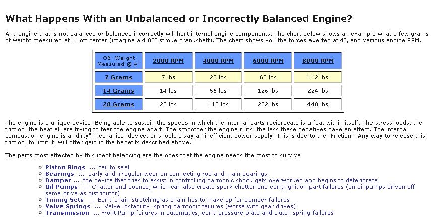
So what does this actually mean in terms of the forces generated inside an engine? An imbalance of only 1/4 oz. (7 grams) located four inches out from the center of the crank on a counterweight will generate a force of about 7 lbs. at 2,000 rpm. At low rpm, you would hardly feel a thing. But at 8,000 rpm, that same force would grow to 114 lbs. with every revolution of the crank. If this same engine had one ounce (28 grams) of imbalance, the forces generated would be multiplied by a factor of four, generating 456 lbs. of unwanted gyrations at 8,000 rpm! That’s enough vibration to rattle your teeth and pound the heck out of the main bearings. It’s also wasted motion that goes into shaking the block instead of spinning the crankshaft. Consequently, imbalance hurts horsepower as well as smoothness and engine longevity.

The factory balance of crankshafts can vary a great deal depending on the application and the OEM tolerances. For a low rpm stock engine, plus or minus 8 to 10 grams or more may be close enough for the average Joe. For a street performance engine, those numbers should come down to plus or minus 3 grams or less. And for a high revving NASCAR engine that spends most of its time at 8,500 to 9,500 rpm, plus or minus 1 gram or less is the rule.

The longer the stroke on the crankshaft, the more important balance becomes because of the distance factor. A longer stroke moves metal further from the axis of rotation and magnifies its effect on balance. It’s not unusual to find imported stroker cranks with as much as 80 to 90 grams of imbalance! These cranks obviously need to be reworked if they’re going into a high revving performance engine.

In recent years, some racers are even scrutinizing camshaft balance. Cam balance is usually not much of a factor because the cam only turns at half the speed of the crankshaft, and the lobes do not protrude very far from the shaft itself. But in a high revving NASCAR engine, cam imbalance can cost the engine as much as 20 horsepower because of the valvetrain harmonics it creates.

ALWAYS CHECK BALANCE
One thing to remember about engine balance is that anytime you replace parts or assemble parts from various suppliers, it affects balance. No two parts are manufactured exactly the same and there will always be some variation in weight. Stock OEM piston weights can vary quite a bit, and even aftermarket performance pistons may not be perfectly matched in a set (though most high quality performance parts are weight-matched). Even so, balance should always be checked and corrected as needed to match the needs of the application. On a stock engine, close enough may be good enough, but on a performance engine there’s much less margin for error.

Changing bore sizes or piston types will affect balance. Changing piston heights, rod lengths or the type of rods (steel, powder metal or forged aluminum) will affect balance. Replacing a stock crank with an aftermarket performance crank or a crank with a different stoke will affect balance. You can’t just throw the parts together and hope the engine will be in balance (which is what a lot of mail order DIY engine builders do!). You have to weigh and balance the individual parts and make sure they work harmoniously together.

BALANCING FUNDAMENTALS
Balancing requires several pieces of equipment: a highly accurate digital scale for weighing pistons, wrist pins and connecting rods, and a spin balancer for rotating parts such as the crankshaft, flywheel or flex plate, torque converter or clutch, harmonic balancer and crank pulley. You’ll also need a drill stand and/or milling machine to make corrections.

The first step in balancing a crankshaft is to weigh all the reciprocating parts starting with the pistons, wrist pins and ring sets. The idea here is to determine the weight of each part, find the lightest pistons, then match the weights of all the remaining pistons to the lightest one by grinding or machining metal off the balancing pads, skirts and/or pin bosses of the heavier pistons. The goal is to match weights to within one gram or less.

The next step is to weigh the big ends and small ends of the connecting rods. The small end is reciprocating weight while the big end is rotating weight. Each end must be weighed separately by supporting one end on the scale while the other end is supported by a stand. The small ends of the rods can then be equalized by grinding metal off the balance pads at the top of the rods. The weights for the large end of the rods can be equalized by grinding metal off the balance pads on the rod cap. As before, the goal is to equalize all weights to one gram or less.

NOTE: Removing metal from the big end of the rod will change the overall weight of the rod slightly, so it may be necessary to go back and recheck the small end weights and do some additional grinding to keep the small end weights equal.

Next comes some math. The weight of the reciprocating parts (the piston, ring set, wrist pin and small end of the rod) must be added together to calculate the amount of bobweight needed to balance the crank. Bobweights are attached to each of the crank’s rod journals to simulate the reciprocating mass of the pistons and rods. On a V8 engine, the bobweight will usually be 100 percent of the weight of the rotating components (the big end of the rod, the rod bolts and bearings) plus 50 percent of the reciprocating weight (pistons, rings, wrist pin and small end of the rod). On many racing engines, “overbalancing” the crank by using 55 percent to as much as 70 percent of the reciprocating weight can help smooth out high rpm vibrations. On straight four and six cylinder engines no bobweights are required. With V6 engines, a different fraction of the reciprocating weight is needed because of the angularity of the crank (typically 39.4 percent of the reciprocating weight on a 90° V6).

On some balancers, it is also possible to use “simulated” bobweights via the balancer software if you’re balancing a run of identical crankshafts. Once you’ve determined the required bobweight for one journal, you can simply enter that value for each succeeding crank without having to actually bolt weights on the crank. This saves time and improves consistency.

SPIN BALANCING
To spin balance the crank, the crank is mounted on the balancing machine support stanchions. The crankshaft should be checked for straightness because a bent crank will wobble as it rotates – which may fool the balancer into thinking the wobble is due to imbalance. Straightness can be checked with a dial indicator at the center journal.

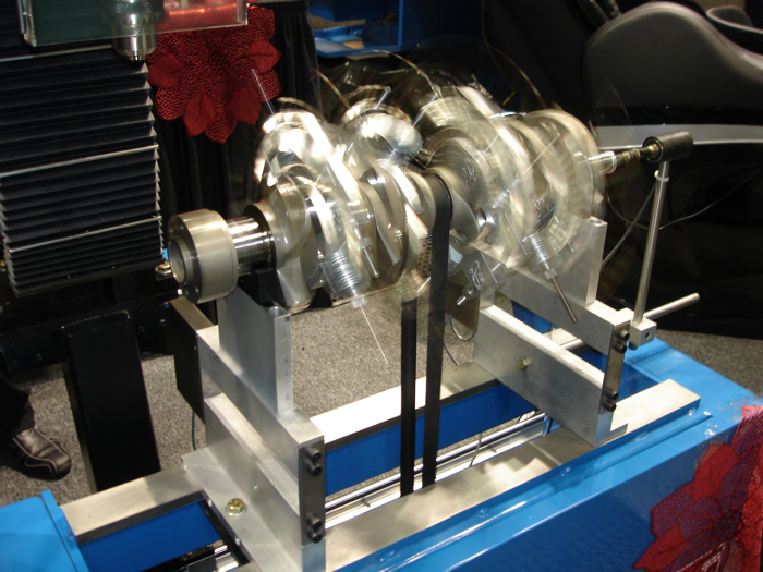
The balancer will then spin the crank to about 500 rpm and determine the magnitude and location of any imbalance it detects. Many balancers today can detect imbalance as small as .01 grams, which is far more than what’s actually needed to achieve a balance of plus or minus one gram or less. The balancer detects imbalance by measuring the displacement of the support stanchion sensors while the crank is spinning. Readings are taken in 1 to 3 degree increments (6 degrees on older balancers), and compared to the position of the crank as it rotates. Imbalance changes the crank’s center of gravity, causing it to wobble off center as it rotates, and the greater the imbalance, the more it wobbles and shakes.

Now comes the magic part. The balancer software looks at the sensor inputs and calculates the amount of the imbalance and its location. The weight is then displayed in ounce-inches or gram-centimeters, and its estimated location is shown in degrees from a reference position.

Corrections can then be made by drilling holes or machining down the outside diameter of the counterweights to remove metal. Or, if more weight is needed, you can weld metal to the counterweights, or drill holes (or use existing holes) to add plugs of heavy metal to the counterweights (Mallory metal is 1.5 times as heavy as lead, and is often needed on stroker cranks and ultra-light racing cranks).

Removing weight requires locating the drill bit precisely and drilling to an exact depth. The software on many newer balancers can calculate the size and exact depth of the hole(s) to be drilled, as well as the best place to locate heavy metal if weight needs to be added. On older machines, corrections typically require much more skill and guesswork. You drill out what you think is the right amount of metal to remove, then cross your fingers and spin the crank again to check the balance. Then you drill or plug some more, spin again, and repeat as many times as needed until you finally get it right. This can sometimes leave the crank looking like a piece of Swiss cheese, which is not good because too many holes may weaken the crank or create windage and drag problems at high rpm.

Making corrections also involves separating one end of the crank from the other because imbalance at one end will affect the other. On older balancers, corrections made at one end of the crank often upset the balance at the other end, requiring repeated spins and corrections until both ends are in balance. On most newer balancers, the software takes this into account and splits the forces apart so corrections that are made on one end won’t upset balance on the other end. It’s like cutting the crank in half and balancing each half separately while also taking into account the balance on the other end. This is called “dynamic plane separation” and is a time-saving feature you want if you’re shopping for a new balancer. The main advantage of dynamic plane separation is that it does a superior job of isolating vibrations so corrections can be made more quickly and accurately. It reduces the back and forth corrections and repeat spins that can eat up valuable shop time.

Multi-plane balancing is also possible on some machines to segment the crankshaft electronically into even smaller sections. This can be helpful in situations where one area of a crank has a lot of imbalance (one end or near the middle).

If a crank is externally balanced, the flywheel and harmonic balancer must be bolted to the crank for a final balance check, and corrections made as needed by adding or removing weight on the flywheel or harmonic balancer to even out the forces. Externally balanced cranks typically have smaller counterweights that are not sufficient by themselves to cancel out all the vibrations of the pistons and rods. An externally balanced crank can sometimes be converted to an internally balanced crank by adding heavy metal to the counterweights. Otherwise, the index position of the flywheel must be maintained with respect to the crank if the flywheel is removed and reinstalled to maintain proper balance.

SHOPPING FOR NEW EQUIPMENT
Whether you’re shopping for your first balancer, adding an additional balancer to expand your business, or replacing an ancient balancer that has outlived its usefulness, there are a variety of machines from which to choose. Balancers have improved a great deal in recent years thanks to better software, better hardware and more user friendly controls. Many balancers now have full color displays and Windows-based software that make them easier to use, even novice users. Graphic displays that show you exactly where the corrections are needed reduce errors and save time.

Balancer manufacturers typically sell two kinds of equipment: balancers for use with existing milling machines, and stand-alone units that include a milling stand or drill press as standard equipment or an option. Balancers come with basic digital displays or PC-based full color displays and various software packages. Bobweights may be included or available at extra cost. Obviously, the more features you want, the more you’ll pay.

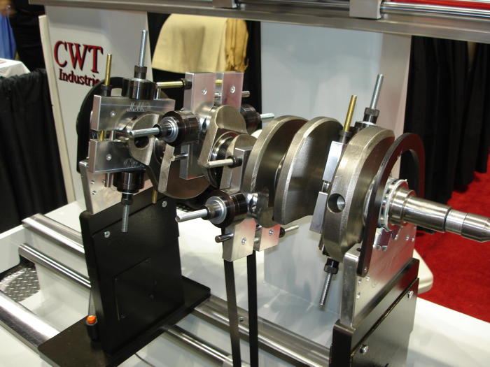
CWT INDUSTRIES
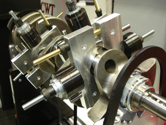
Randy Neal of CWT has been making waves in the industry with his “three plane” balancer. He says dynamic two-plane balancers can sometimes be fooled by certain kinds of crankshaft imbalance. His “third plane analysis” software and hardware does a better job of isolating and identifying force vectors to reduce the time it takes to balance a crank by a third or more. Additional software includes unlimited parts and history data base, “PDQ” (Precision Drill Qualifying) to help the user determine the best locations for drilling correction holes (to minimize the number of holes that have to be drilled), and “HMV” (Heavy Metal Vector) to plot the best locations for adding metal if more weight is needed.

CWT sells three balancers: the Multi-Bal 1000 for Mill mounted applications and the stand-alone Multi-Bal 2000, are both standard two-plane balancers with polar and vector displays at a base price of $9,995 and $12,500. The Multi-Bal 5000, which is CWT’s three-plane balancer starts at $15,900. The Multi-Bal 5000 comes with touch screen controls, heavy duty work cabinet and a 4,100-lb resin-filled steel base for added rigidity, which eliminates any residual vibrations that could affect balancing accuracy. Neal says the balancer’s sensors can detect motions as small as .25 microns (.00000975?) and inspects imbalance position 720 times per revolution, which adds to the machine’s high degree of accuracy. Options include; heavy duty gear head mill/drill, digital drill depth monitoring, heavy metal drill stand and “moment-matched bobweights,” universal flywheel arbor and direct communication weight scales system.

G & H BALANCER SERVICE
Gary Hildreth says his company does not make their own balancers, but they do sell Turner balancers. “Our niche is balancer repair and service. We have belts for every balancer ever built and can service any brand of balancer.” The company also sells bobweights and other balancing accessories.

Hildreth says that within the next 10 to 12 months, he will be introducing a new electronics package to upgrade older Stewart Warner balancers. He estimates there’s still 4,000 of these older balancers out there, and most could benefit from an electronics upgrade. No word yet on the selling price of the upgrade package.

HINES
Hines sells three basic models of balancers: the “Eliminator,” a $12,495 hard bearing balancer with a black and white LCD plasma display, the $14,900 “Dominator,” which is a PC-based hard bearing balancer, and the $15,900 “Liberator,” their top-of-the-line PC-based balancer.

John Witt of Hines says the Dominator and Liberator both include a Graphic Depth Encoder which ties the drill quill to the display screen to show the operator where and how deep to drill correction holes. Both machines also offer dynamic plane separation for faster, more accurate corrections – a capability, Witt says, that Hines has had since 1979. The Liberator also includes a 19? flat screen color display, 24? x 36? workstation cabinet so new rod and piston corrections can be done without leaving the machine.

SCHENCK TREBEL
Rich Idtensohn says his company is the world’s largest manufacturer of dynamic balancing equipment. Its CS30 Balancer is an industrial-based, multi-plane, hard bearing balancer that starts at $18,000 and can go as has high as $30,000 depending on options. The CS30 Balancer has two options for instrumentation, the CAB 700 digital display or the CAB 803 PC-based Windows NT touch screen display.

Both instrumentation packages provide an automatic tolerance calculation for each plane, and provide an electronic protractor so the operator can visually pinpoint the exact location to make corrections. The system includes optional drill depth indicator software that shows how much drilling is needed to make a correction. The machine also comes with a heavy-duty drill correction unit that rotates 360°.

“Many manufacturers offer similar features that make balancing easy,” says Idtensohn. “But the real difference is a matter of accuracy, sensitivity and repeatability. The fact of the matter is, if engine builders take a closer look at their results many just aren’t getting what they think they’re getting. A few simple repeatability tests can be very revealing and can make a substantial difference in performance.”

Schenck is also offering a new balancing certification program, the first of its kind says Idtensohn. The three-tiered program offers Level 1 Balancing Operator Certification, Level II Balancing Technician Certification, and Level III Balancing Specialist Certification. The program is designed to provide a standard benchmark for excellence and productivity, as well as individual recognition for technical skill and aptitude. Anyone who has completed their Fundamentals of Balancing, Jet Engine Balancing or Pump & Impeller Balancing seminars are eligible for Level 1 or II certification. Candidates for Level III certification is open to those who can demonstrate in-depth knowledge of balancing theory principles and practices, vibration analysis, rotor dynamics and measuring instrumentation.

SUNNEN
Sunnen sells two balancers, a DCB-750 with digital controls that starts at around $17,000 and a DCB-2000 with Windows XP instrumentation touch screen display that starts at around $20,000. Tim Meara of Sunnen says both machines are mechanically the same except for the controls. New features on the DCB-2000 include counterweight cutting software for calculating how much metal to remove from the counterweights if a user prefers to turn down the counterweights rather than drill holes in them. New vectoring software shows where to add heavy metal to cranks and allows the use of existing holes to save extra drilling.

Meara says Sunnen’s balancers are two-plane balancers. The DCB series balancers are extremely precise, measuring unbalance from .01 to 1,000 grams on work pieces weighing up to 500 lbs. (226 kg.). The balancers can handle anything from small engine cranks to diesel cranks. Also included is a heavy-duty drill tower and steel base that is concrete-filled for extra stability for more precise results.

T & S MACHINE
Tim Whitley says his company has a marketing agreement with Pro-Bal to sell their balancers. The PB500 is a basic microprocessor controlled hard bearing balancer that starts at $11,000 bare up to $23,000 complete with the drill press and automotive tooling package while the “Edge” bolts to a vertical milling machine and sells for $7,500.

Placing the “Edge” on a milling machine saves floor space and offers the best drilling machine possible when correcting the imbalance.

“These balancers are capable of force and couple balancing, which some people now call three plane balancing. Separating the forces out allows the user to better understand what’s going on so corrections are easier and faster to make,” said Whitley.

Accuracy is to .01 oz./in. detectable unbalance, and spins take only 20 seconds. The compact design of The Edge takes up less space than other balancers and can be converted to surface heads and blocks, and do seat and guide work.

TURNER TECHNOLOGIES
Turner Technology sells three models of balancers. The Series 1 balancer is for automotive and small engine parts, and can handle cranks up to 7? in stroke and flywheels up to 16-1/2? in diameter over the table. The Series 2 balancer is a heavier, taller machine that can handle cranks of greater stroke with larger flywheels. The Series 3 balancer is taller yet to handle even larger shafts. Series 2 and 3 balancers can have optional roller bearing tops for balancing very heavy shafts.

Turner Technology’s Michael Turner says its balancers offer powerful dynamic plane separation with third plane analysis for fast, accurate balancing, even with a large amount of couple. “Our software allows you to balance any section of a crankshaft without changing the balance elsewhere, so fewer corrections are needed. We also use a closed-loop motor control design for improved accuracy.”

The machines use an interface system that allows the balancers to be connected to any laptop or desktop running Windows 98 through XP. This helps keep the cost of the equipment down, says Turner, and simplifies upgrades. Turner says heavy metal software is included in the standard package along with free lifetime software upgrades. Digital scale readings are automatically transferred into the control software to save time and reduce errors. Balancer packages start around $8,000. You also get one of the best warranties in the industry with an option to extend the warranty at any time, according to Turner.
 
Tipping the Scales

by Larry Carley - Dec 18, 2015


Today’s balancers have smarter software and better user interfaces that make learning and using a balancer much easier (courtesy of CWT Industries).
Our readers are certainly familiar with the benefits of engine balancing, and few would disagree that balancing is a worthwhile effort whether you are rebuilding a stock engine or putting together a performance motor. A small imbalance will multiply exponentially as engine speed increases, generating forces that create severe vibrations that may eventually lead to bearing or crankshaft failure.

The basics of engine balancing have not changed over the years, but some of the nuances have. The equipment used to balance crankshafts has also become more sophisticated, faster to learn and easier to use thanks to smarter software, better user interfaces and more informative display graphics.

Most of today’s balancers can balance a crank in less time with fewer spins than the type of equipment that was commonly used in the past. So if you are still using an antiquated machine to spin-balance cranks, you should check out the latest generation of balancers to see what you are missing.

The basic procedure for balancing an engine is still the same. You generally start by weighing all of the reciprocating components (rods, pistons, wrist pins, piston rings and bearings) on a highly accurate digital gram scale to establish which rod and piston are the lightest. The rest of the rods and pistons are then machined to match the weight of the lightest ones in the set.

The next step depends on the type of engine (inline, V-block or horizontally opposed) and the type of crankshaft. If we are talking about a straight inline four-cylinder engine, the next step would be to mount the crankshaft in a balancer, spin it and make the necessary corrections to achieve neutral balance. If an engine is internally balanced, you spin the crank by itself. If it is externally balanced, you mount the flywheel or flexplate on one end of the crank, and the harmonic dampener on the other and balance the rotating assembly as a unit.

Bobweights to simulate the rotating and reciprocating mass of the rods and pistons are required for most V-block engines, but are usually not necessary with flat plane four-cylinder cranks because the rod journals are positioned 180 degrees apart. Two pistons (#1 and #4) are at Top Dead Center (TDC) while the other two (#2 and #3) are at Bottom Dead Center (BDC). The two pistons that are up alternate compression strokes as do the two pistons that are down. The typical firing order would be 1-3-4-2 every 180 degrees of crankshaft rotation. Thus, the reciprocal forces generated by the two pistons traveling up cancel out the forces generated by the two pistons traveling down – assuming all of the reciprocating components are of equal weight.

It’s the same story with a horizontally opposed four or six-cylinder engine like that in a Porsche or Subaru. You don’t need to use bobweights to balance a flat plane crank in one of these engines because the reciprocal forces generated by the pistons that are opposite each other cancel each other out.


V-Block engines require bobweights to offset the reciprocating weight of the rods and pistons. For most engines, the bobweights should equal 100 percent of the rotating weight (big end of the rod and bearings) and 50 percent of the reciprocating weight (small end of rod, wrist pin, pistons and rings). But for some applications, adding or subtracting a few percent from the bobweight may improve smoothness and performance (courtesy of CWT Industries).

Bobweight Debate

Some engine builders disagree with these generalizations and say you get a better balance with bobweights on a four-cylinder flat plane because the weights help simulate the bending forces the crank experiences in a running engine. Others say it’s a waste of time to create and install bobweights on a four-cylinder crank. There’s also a chance one or more bobweights might not be the correct weight or not positioned correctly on the rod journals which could throw the balance job off.

If a particular balancing technique works for you and you haven’t had any problems with it, it’s probably best to stick with the technique you have been using. On the other hand, if you feel there’s room for improvement, trying a different technique (bobweights or no bobweights) might give you better results.

Spin Balancing

If an engine is an inline six-cylinder, bobweights are generally not used when balancing the crank. The throws are positioned 120 degrees apart so the engine will fire evenly. Similar to a four cylinder, the reciprocating forces generated by the pistons cancel each other out so the crank can be spin balanced without bobweights.

With V6, V8, V10 and V12 engines, it’s a different story because the cylinders are not in the same plane and the forces generated by the up and down motions of the pistons and rods are in different directions and at different times. With most V8 engines, the cylinder banks are 90 degrees to each other and the crankshaft is a cross plane design with the rod throws spaced 90 degrees apart. With V6 engines, you might have a 90-degree block, a narrower 60-degree block, or in the case of a VW a very narrow 18-degree block. Consequently, the forces generated by the rods and pistons reciprocating in different planes require bobweights to simulate the effects when balancing the crank.

To create a bobweight, you have to separate rotating mass from reciprocating mass. Rotating mass is the big end of the connecting rod and rod bearings. Reciprocating mass is the small end of the rod, the wrist pin, piston and rings. Figuring out which is which requires weighing the big end of the connecting rod on a scale while the small end is supported by a pin or hook. Once you know the big end weight, you can subtract that from the total rod weight to determine the weight of the small end of the rod. Then you add that number to the weight of the wrist pin, pin clips or retainers (if used), piston and ring set to determine the reciprocating weight. Several grams (2 to 5) also need to be added to the total to compensate for motor oil in the bearings and on the parts. The bobweight can then be assembled with weighted washers until the desired weight is achieved.

With most 90-degree V-blocks, each bobweight is equal to 100 percent of the rotating mass (big end of each rod), plus 50 percent of the reciprocating mass (small end of the rod plug, the piston, wrist pin and rings), times two (2X) because two rods share each crank journal. This is the standard balancing formula that applies to most 90-degree V-blocks for street and performance use.

The bobweights are installed evenly on the center of each crank journal. The crank is then spun on the balancer so its sensors can detect the amplitude and location of any imbalance in the crank. The machine shows you where to remove (or add) metal to correct the imbalance. It may take several spins and corrections before the desired degree of balance is finally achieved.

A stock Chevy 350 will usually run smooth enough if it is balanced to one ounce-inch (28.35 grams). One ounce-inch means there is one ounce of imbalance one inch from the centerline of the crank. A better spec to aim for with a stock build would be 1/2 ounce-inch (14 grams) or less. Some OEMs and production engine rebuilders say they balance their engines to 1/4 ounce-inch (7 grams). Some are even closer. The balance tolerance for current Ford V-6 engines for normal (not HP) applications is now 0.16 ounce-inch or less. Other OEMs are using similar specs. This would be a good target for a well-balanced street/strip engine. For a high revving race engine, however, many experts recommend getting the balance down to 2 grams or less!
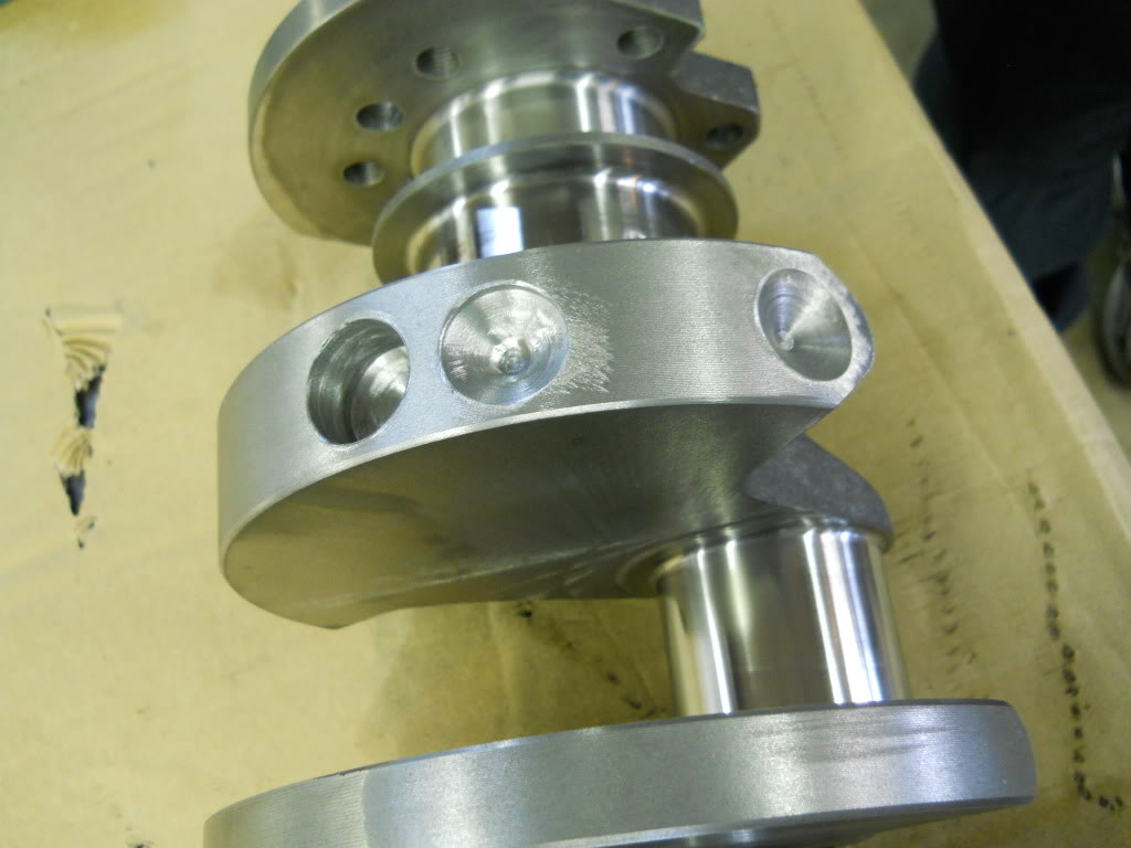
The lower the number you are aiming for, the more spins and corrections it will take to get there. The resolution on most balancers today is under a tenth of a gram, with a repeatability factor of about plus or minus half a gram. Realistically you’ll never achieve zero (perfect) balance because it’s beyond the resolution of the balancer and the bobweights. Besides, nobody really needs an absolute zero balance. If you can get it down to 2 grams or less, that’s good enough. There’s also the variable of how much oil affects balance inside a running engine at high RPM. It can change depending on oil viscosity, whether pistons use oil squirters or not, bearing clearances, oil pressure and flow, and coatings on parts.


Modifying Counterweights?

All kinds of modifications can be made to the counterweights when balancing a crankshaft. Sometimes the counterweights will be machined to a knife-edge to reduce windage and drag, or cut down to provide extra piston clearance in a stroker motor. Any modification that changes the shape and mass of the counterweight will affect balance.
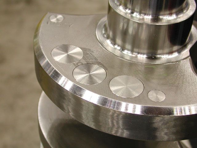
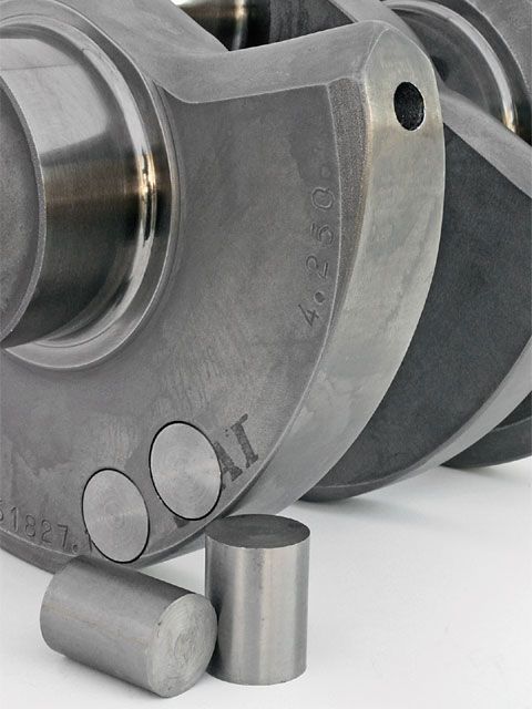
Typically, you drill holes of various diameters and depths into the counterweights to remove metal when lightening is required. But holes can create extra windage and drag. So if you want to be really slick, you can machine down the outer circumference of the counterweight slightly, or to make the counterweight thinner by removing metal from its side. Turning down the outer diameter of the counterweights may also be necessary if the pistons and rods weigh significantly less than the stock components.

Turning down the outside diameter of the counterweights removes weight where it has the most effect in terms of inertia. A lighter crank will rev faster than a heavier crank, obviously, but reducing the mass of the counterweights too much can also have a detrimental effect on torsional control. That’s because the mass of the counterweights provides momentum that helps dampen the twisting motions the crank experiences when the engine is running. Loss of torsional control can lead to excessive motion, metal fatigue and crank failure. The same thing can happen if the harmonic dampener on the front end of the crank is removed or is too small or too light for the application (bigger is actually better).

The mass and position of the counterweights on a stock crank are designed to offset the weight of the pistons and rods. If you are building a performance motor with longer or heavier rods and the counterweights don’t have enough mass to offset the reciprocating weight, gun drilling the rod journals lightens the crank a bit and effectively increases the effect of the counterweight.

If you are buying a custom aftermarket crank, weigh the rods and pistons first to determine the reciprocating weight. Then order a crankshaft that has a target bobweight slightly heavier than what you need to balance the engine. This will make balancing the crank quicker and easier because you’ll have to drill fewer holes.

Another option is to externally balance the engine if the counterweights are not heavy enough to offset the pistons and rods. You get the crankshaft as close to neutral balance as you can, then bolt on the flywheel and damper and add weight to these components as needed to balance the entire assembly. However, the external weight places high stress loads on both ends of the crankshaft which can cause deflection and exasperate the original unbalance.

If you can’t get a crank to balance because there isn’t enough metal in the counterweights to offset the pistons and rods (which may be a problem with long stroke motors), a hole can be drilled parallel to the crankshaft axis in the counterweights to accept plugs of Mallory heavy metal (tungsten). The plugs should be installed with a slight interference fit and/or locking compound so they can’t work loose.

Another option is to externally balance the engine if the counterweights are not heavy enough to offset the pistons and rods. Once you get the crankshaft as close to neutral balance as you can, bolt on the flywheel and damper and add weight to these components as needed to balance the entire assembly.

Overbalancing

For most performance applications, using 50 percent of the reciprocating weight for the bobweights when balancing the engine yields good results. All engines will experience harmonic vibrations at certain RPMs, but will generally run fairly smooth throughout the RPM range using the 50 percent figure. But there are exceptions.

High-revving engines (say 8,000 to 12,000 RPM), as well as engines that are blown, turbocharged or run on nitrous may benefit from “overbalancing” the crankshaft. Overbalancing adds an additional 1 or 2 percent to the reciprocating weight when creating the bobweights. The extra mass helps offset the extreme reciprocating forces that are generated at really high engine speeds and loads. Overbalancing an engine at 51 or 52 percent of the reciprocating weight often helps smooth out high speed vibrations. It may also add some additional horsepower that would otherwise be lost due to ignition and valve timing fluctuations.

Overbalancing can smooth things out at high speeds and loads, but it also makes the engine unbalanced at lower RPMs. Usually that doesn’t matter because a race engine doesn’t spend much time idling or running at low speed or load. And at low speed, any imbalance that’s present has much less effect.

In some cases, slightly underbalancing an engine can smooth it out at certain speeds, too. Using 48 to 49 percent of the reciprocating weight can sometimes smooth out a large displacement long stroke engine that otherwise tends to feel rough with a standard balance.

Figuring how much overbalance or underbalance to use in a given application is a black art based on engine displacement, bore, stroke, rod length, rod ratio, speed and load. Some people claim they have formulas that predict how much overbalance or underbalance should work. But it usually takes some experimentation to find the “sweet spot” that produces the best results in any given engine.

Overbalancing usually does NOT provide any benefits for street engines or performance engines that don’t rev beyond 7,000 RPM, and may in fact be detrimental because of the vibrations it may produce at lower speeds.

V6 Balancing

With V6 engines, the percentage of reciprocating weight varies depending on the angle between the cylinder banks and whether the crankshaft is even-fire or odd-fire. For a typical 90-degree V6, the recommended reciprocating weight for the balancing bobweight is often 50 percent, the same as a 90-degree V8. But for some engines, like an externally balanced Buick 3800 V6, the recommended reciprocating weight is only 36.6 percent. Ford says to use 44 percent of the reciprocating weight for its odd-fire 4.0L V6, but to use 50 percent of the reciprocating weight if a 4.0L V6 has a split-pin, even-fire crank. For its 90-degree 3.8L V6, Ford recommends using 39.4 percent of the reciprocating weight for the bobweight.

The bottom line here is that the recommended reciprocating weight for the bobweight can vary depending on the application. So make sure you find out what the recommended percentage is so the bobweights will be correct for the application.

Odd Applications

Bobweights are also required for inline five-cylinder engines as well as high performance V8s that use a flat plane crank. Ford has gotten a lot of publicity recently about the flat plane crank it is using in its 2016 Mustang GT350. The 5.2L “Voodoo” V8 has been optimized for track performance with an over-square bore-to-stroke ratio of 94mm to 92.7 mm. The naturally aspirated engine revs to 8,250 RPM and makes 526 horsepower at 7,500 RPM and 429 ft. lbs. of torque at 4,750 RPM.

Ford went with a flat plane crank instead of a conventional cross plane crank because the flat plane crank improves the firing order and exhaust scavenging of the engine. Also, the crank has smaller, lighter counterweights that allow the engine to rev and decelerate more quickly, which is exactly what you want in a track car motor. The trade-off, however, is increased roughness due to second order vibrations produced by the flat plane crank and revised firing order. You can’t balance those kinds of vibrations out of the motor by rebalancing the rotating assembly. The only way to tune them out is with counter-rotating balance shafts, which Ford chose not to use because of added weight and complexity that isn’t needed in a track motor. This engine was not designed to be a smooth-running street engine like the Mustang’s regular 5.0L V8, so the extra vibrations are a consequence of the change from a cross plane crank to a flat plane crank. Ford says it spent a lot of time beefing up the bottom end of the block to handle these vibrations. Specially tuned hydroelastic motor mounts are also used to help isolate the engine vibrations from the body.

Several years ago, Lingenfelter built a 358 cubic inch Chevy LSX engine with a flat plane crank to see what it would do. The naturally aspirated engine put out 621 horsepower at 9,000 RPM.

Ferrari has also used flat plane cranks in many of its engines, and flat plane cranks have also been used in Formula 1 and Indy engines. Most of these applications are smaller displacement, short stroke big bore engines that can rev like crazy. These engines have a lot of vibrations, which are mitigated somewhat by the shorter stroke of the crankshaft and the higher RPMs. Even so, all the recent buzz over Ford’s new 5.2L Voodoo V8 has some people wondering if a flat plane crank is the way to go in spite of its balance and vibration issues. According to one aftermarket crankshaft manufacturer, flat plane cranks have some advantages and make sense in certain applications (like a track car), but they would not be a good choice for a typical street performance engine. Switching to a flat plane crank would also require a different cam and different exhaust headers.

Balancing Wrap-Up

The typical aftermarket automotive engine balancer only checks first order vibrations. It is not designed to detect second and third order vibrations. That said, it’s impossible to build an engine that is perfectly balanced from idle to peak RPM. All engines will experience some type of harmonics within various speed ranges.

The goal of balancing an engine, therefore, is to end up with a balance that delivers the smoothest results over the broadest range of engine speeds (stock and street applications), or the smoothest balance within the engine’s peak power band (race engines). If a standard balance doesn’t get you there, you may have to experiment with some overbalance or underbalance.

http://www.hotrod.com/how-to/engine/ccrp-0803-engine-balancing/

http://garage.grumpysperformance.com/index.php?threads/selecting-a-flywheel.1042/#post-1969

http://www.enginebuildermag.com/201...uilding-tips-to-reduce-nvh-and-increase-life/


Crankshaft Balancing with Tungsten Weights
Crankshaft balancing is crucial to engine performance. In race cars, aircraft or other high-performance engines, professionals who are serious about crankshaft balancing rely on Mi-Tech Metals to provide the high-quality tungsten weights they need.

A number of tungsten weights are available in standard, stocked sizes in the Crankshaft Weight store. We also have free online tools to calculate tungsten weight and convert units of measure. And, as always, our Mi-Tech professionals are eager to help you determine the best solution for your particular need.

To determine which tungsten crankshaft weights will work best in your engine, it’s important to remember:

  • Regarding density:
    • Density of HD17 tungsten = 17 grams/cc
    • Density of steel = 7.83 grams/cc
  • To determine the weight of high-density tungsten or steel:
    • Weight (grams) HD tungsten = Dia²(inches) x 12.87 x Length(inches) x 17
    • Weight (grams) steel = Dia²(inches) x 12.87 x Length(inches) x 7.83
  • When switching from steel to HD tungsten weights, every gram of steel removed is replaced with 2.17 grams of HD tungsten. You have therefore increased the weight 117%.
    • Example:
    • If you drill out 90 grams of steel and replace it with HD tungsten, you’ve replaced 90 grams with 195.3 grams. The net additional weight will be 105.3 grams.
    • 195.3 – 90 = 105.3 grams
    • An easy way to calculate the net additional weight added when using HD tungsten is to multiply the grams of steel removed by 1.17.
    • 90 x 1.17 = 105.3 grams added weight
  • The weights listed on our price sheet and the figures shown above are rounded to the nearest one-hundredth of a gram and can vary with the density of HD tungsten and steel, as well as dimensional tolerances.
  • The cost of HD tungsten weights will be higher because of additional material normally added to length.
  • We suggest you overbalance slightly and remove material to fine-tune crankshaft balancing. Detailed information is available on the balance sheet (available by request).
 
Last edited:
Engine Balancing, Part 1
“An Introduction to Engine Balancing”

By Ted Eaton

Although the terms “blueprinted and balanced” are typically synonymous with any kind of performance buildup of an engine, it must be noted is that these two terms are completely different in relation to their perceived functions and are generally performed independently of each other. Whereas “blueprint” specifically targets an engines fits, tolerances, volumes, and/or settings, the “balance” deals with the physics of achieving a rotating mass that is the most conducive to transmitting as much potential power as possible to an engines flywheel rather than having it wasted within the confines of the block. By eliminating power robbing vibration or harmonics that can be caused by a state of out of balance, power or torque that would normally be dissipated through an engines main bearings and into the block can instead be redirected to the drive end of the crankshaft proportionally by the degree to which the rotating mass is balanced. Simply stated, the better the balance, the more the potential power that can be seen at the flywheel. For the driver of a vehicle with a balanced engine, it’s simply a physically smoother running engine with improved acceleration.

ebalance1001.gif
ebalance1002.gif
The physics of balancing can be broken down into two types of imbalance, static and dynamic. Static imbalance will manifest itself as a maximum amount of out of balance in a single area or plane along the outer most surface of a rotating axis. On the other hand, a rotating part can be in a perfect state of static balance but can be off significantly when examining its dynamic balance. If a vibration is observed, static imbalance is the force most likely being felt but dynamic out of balance can also be present depending upon the rotating mass’s length. Even when physical vibration is not being felt, dynamic imbalance can be present in severe enough degrees to be quite destructive or power robbing although no shake or vibration is physically evident. Static out of balance can be found in any rotating part regardless of the length along its rotating axis but dynamic out of balance becomes more significant as rotating pieces increase in length along its rotating axis. Very narrow rotating parts such as flywheels will not exhibit much in the way of dynamic out of balance but can be good examples of static imbalance. A longer item like a crankshaft may not show evidence of being out of balance statically but can be off significantly when looking at its dynamic aspects.

Over the years, set rules or best practices for engine balancing have been established for the various engine designs. These practices at their best are a compromise dealing with conflicting forces that try to share the same physical space normally defined as either rotating or reciprocating mass. While rotating mass can be described as that which travels only in a circular motion such as the crankshaft or the connecting rod big ends, reciprocating mass would be those components that are attached to the crankshaft but travel in a predefined non-circular motion such as the pistons or the connecting rod small ends. Getting back to conflicting forces, the connecting rod does not have a distinct line separating the reciprocating mass from the rotating mass due to the fact that the area of the rod between the wrist pin and the crank pin exhibits the traits of both reciprocating and rotating mass. As this in-between area gets closer to the crank pin, it exhibits more rotating mass characteristics than reciprocating; likewise, as this same area gets closer to the wrist pin, it exhibits more reciprocating mass characteristics than rotating. For this reason, the longer the rod and/or the cranks stroke, then the more this ambiguity. This ambiguity and how to compensate for it will be discussed in a later article in this series.

To precision balance an engine, all pieces of the rotating assembly must be considered. A list of these parts will include the crankshaft, harmonic damper or front hub, flywheel, the clutch disk and pressure plate if a manual shift transmission is being used, connecting rods, pistons with their pins and respective locks, compression and oil rings, rod bearings, and the lower timing gear. Basically everything that moves or rotates as part of the engine assembly short of the camshaft and its attached gear. Also worth considering are the belt pulleys and their retaining bolts. All machine work or modifications including rod reconditioning, piston dome or valve relief machining, and general deburring or polishing of any of the internal engine parts must have been already performed prior to having the assembly balanced as doing so after the fact will only nullify the effects of having the rotating assembly precision balanced.

When taking all the necessary parts to your favorite shop for balancing, it’s important to note that the connecting rods or the piston rings must not yet be installed on the pistons. Likewise, the rod bearings do not need to be installed in the rods or the rods installed on the crankshaft. Because the rods must be balanced end for end separately, they are required to be independent or apart from the pistons. Although the rings could technically be on the pistons during the balancing procedure, they also need to remain uninstalled in order to insure that no machining chips are caught in the ring lands during any of the weight reduction operations being performed.

The balancing operation as performed by your machine shop can be separated into two basic operations; weighing and/or match weighing the various components and then spin balancing the crankshaft itself. Depending upon an engines design, there may be a specific order in which these operations are performed. Most engines with opposed or inline cylinders (i.e.. 4 & 6 cylinders) normally do not require a bobweight to be attached to the crankshaft rod journals prior to spin balancing in order to simulate any of the component pieces (rods, pistons, etc.) that are normally attached to the crankshaft assembly. This is due to the nature of the physical forces being applied at equally spaced intervals on these engines and subsequently being equally opposed or counteracting. A “V” type cylinder engine on the other hand does not have these forces being applied at the same opposing intervals and depending upon the angle between the opposing cylinders, does require a bob weight installed on each crank pin for balancing purposes that uses 100% of the rotating mass but only a fraction or a percentage of the reciprocating mass for each piston/rod assembly. A 90° V design, which covers a majority of the common V8 engines, requires a bobweight on each crankpin during balancing that represents not only 100% of the rotating mass but also a standard value of 50% representing the reciprocating mass. Even this standard reciprocating factor is subject to change for a 90° V design engine in special circumstances. More on that in a later article in this series.

There are some of the balancing operations that can be performed by the novice in his own shop but the spinning of the crankshaft is best done by those with the appropriate equipment and experience. If so inclined and with a nominal purchase in equipment and materials to do so, the pistons and connecting rods can be independently weighed and appropriately lightened by the enthusiast before sending the crankshaft out to be balanced. A scale reading in grams along with a connecting rod holding fixture that can separate the big end and small end weights would be the bare minimum equipment requirements. Then it’s just a simple matter of finding the lightest piston, lightest reciprocating rod end weight, and lightest rotating end weight and making the remaining component pieces match these weights. The equipment used for lightening operations would be wholly dependent upon the quality of the machining that’s being targeted for as well as the initial design of the pieces that must be lightened. Some parts may require special tools or tooling for machining in order to keep from sacrificing or minimizing the strength of the piece being lightened. For those of you that have a grinder, belt sander, drill press, and/or some form of milling machine available, most lightening operations would be well within your reach. Look for more detail on this in the subsequent articles.

These series of articles are hoped to heighten your awareness of how precision balancing not only increases engine efficiency, but ultimately also increases engine life through reduced internal vibration and unwarranted stress. The next article in this series will cover in detail the differences between external and internal balance. Until then, happy motoring.


“Internal Versus External Balance”

By Ted Eaton

When getting an engine balanced, it’s important to note that there are two different methods in which to have the engine balanced, either internally or externally. As the Ford Y-Block family of engines are all internally balanced as part of the factory design, this is not expected to be an issue but for other engines it’s a subject worth touching base upon here briefly. External balance refers to when the damper, flywheel, and/or other rotating parts outside of the engine block are counterweighted and must be installed as part of the crankshaft assembly to insure the balance of that particular rotating assembly. Whenever possible, the customer should opt for internal balance unless the cost is prohibitive or not effective for the result being desired.

There are two basic reasons an engine becomes externally balanced as part of a factory design. The first is through evolution where an existing engine series was originally designed as internally balanced but has an increase in stroke to the point that the crankshaft counterweights can not be made any larger within the confines of the block in which to compensate for the additional mass requirements. This then requires additional mass to be attached at the flywheel and/or the damper to supplement the existing crankshaft counterweight mass in lieu of a complete new engine crankshaft or block design. The second reason would be in initial engine development and design where the crankshaft can be made lighter which in turn uses less of the costly nodular material typically used to strengthen cast iron. This then allows inexpensive materials to be used at the flywheel and damper to provide for the additional required rotating mass.

There are two inherit flaws in the factory external balance designs. The first would be the stackup of balance variances due to three pieces (flywheel, crankshaft, & damper) that must match up in balance after being independently balanced of each other. Second would be the forced out of balance at high rpm’s this type of balance promotes due to a given amount of non-evenly distributed mass being located in a non-rigid manner outside the confines of the block. This then allows a given amount of flex or twist in the unsupported ends of the crankshaft at that point. The more the counterbalance on the ends, the greater the flex or distortion throughout the crankshaft at a given rpm and the potential for crankshaft deflection or breakage at high rpms.

Although not recommended, there are instances where a balance shop will externally balance an engine that was originally internally balanced. These occurences most often originate from substituting parts that are much heavier than the originals such as heavier connecting rods and/or pistons which causes the crankshaft counterweights to be too light in which to compensate inexpensively. Another instance is where the crankshaft stroke is being increased while the crankshaft counterweights are remaining the same. Although externally balancing as a result of either scenario is performed as a cost savings measure in both time for the shop and expense by the customer, a major problem presented by an externally balanced engine is the inability to change out the modified balancer or flywheel with alternate units at a later date without having the assembly rebalanced. Rather than externally balancing an engine in such a circumstance, there are other options rather than repurchasing lighter components. One such manner is to balance the crankshaft internally through the use of Tungsten, Mallory metal, or other heavy metal in the crankshaft counterweights in order to make them physically heavier. And yet another option depending upon the crankshaft design is to use lightening holes in each of the rod journal throws which will in turn make the crankshaft counterweights artificially heavier without actually having to add weight. Ultimately, cost is typically the deciding factor on what method is used to retain internal balance characteristics in lieu of leaving an engine externally balanced.

Ideally, the engine is best balanced internally which allows replacement dampers and flywheels to be balanced as separate units at a later date to a zero state and placed back on the previously balanced crankshaft with a minimum amount of upset to the crankshafts previous state of balance. The next article in this series will cover in detail how the piston set is match weighed and machined by your local balance shop.


untitled-1-copy.jpg


Here’s a Ford Y-Blk damper that’s been externally balanced!!! This should be avoided as relacement of the damper without rebalancing the crank becomes extremely difficult.

untitled-2.jpg


untitled-3.jpg


All these SBF standard transmission flywheels are externally balanced to the 28.4 oz Ford specification.

untitled-4-copy.jpg


All three of these flywheels will fit either a SBF or 300 Ford Six but all three exhibit different states of balance depending upon the engine and its application.


This SBF flywheel has been balanced to the Ford 50 ounce external balance specification.
 
Last edited:
Engine Balancing, Part 3
“Piston Match Weighing”

By Ted Eaton

ebalance3001.jpg
Match weighing the piston set is just one of the steps that’s performed as part of having an engine balanced. When balancing a V style engine, this operation must be performed before the crankshaft can be spin balanced due to the piston weight being required as part of the bobweight calculation. Although piston weight matching appears to be a relatively simple and straight forward operation, the machining method in which it is actually performed can jeopardize piston strength or its integrity if not done correctly.

In order to weight match a piston set, essentially the lightest piston in a set is identified and the remaining pistons are lightened through various machining operations so that all pistons end up weighing the same. Piston pins can be either weighed with the piston that it’s going to be used with or all balanced independently so that the pins themselves all weigh the same. Whether the pins are weighed with the pistons or done separately is typically determined by the shops preference. Regardless, either method will not affect the final state of balance if performed with tight tolerances that keep weight variation and any subsequent stackups to a minimum. The typical tolerance for this operation is ½ gram for the whole piston set with the pins in their respective pistons but the closer to zero, the better. Merely lightening the heavier pistons so that they match the weight of the lightest is not the only machining that can be performed at this point. Depending upon the piston design, the potential for additional piston weight reduction can be of benefit in that a lighter piston will subject the connecting rod, connecting rod bolts, and the bearings to less stress as well as reduce the total amount of reciprocating mass. This is conducive to a rotating assembly that can accelerate or increase in rpm’s at a quicker rate due to a subsequently lighter crankshaft which ends up having less stored or kinetic energy in which to release. Additional piston lightening at this point could also make the difference in removing weight at the crankshaft counterweights as opposed to actually having to add additional mass to the counterweights if only match weighing the piston set. Still, the emphasis here is to only lighten the pistons to the point where overall strength is not jeopardized.

ebalance3002.jpg
Where to take weight out of the pistons depends particularly upon its design. If taking mass out of the piston’s inside deck portion, then rule of thumb dictates leaving a minimum of 0.200″ thickness. While some pistons have as much as 0.600″ deck thickness and give adequate material to work with, other piston designs are already at the 0.200″ thickness value leaving no room in this area for material removal. Blown applications will typically require much more than 0.200″ material in the deck surfaces so this is yet another consideration. Special care must also be taken in the deck areas under the valve reliefs to insure that sufficient material is remaining under the reliefs after machining. Other areas inside the piston in which to work at for weight removal is in the pin boss, both above and below the pin as well as inside the skirt area or behind the piston ring lands. In extreme cases, the whole of the vertical sides of the pin boss can be machined. All these different options are dependant upon the piston design and exactly how much material is available to work with. Some piston designs create quite a challenge depending upon how much weight must be removed in order to merely weight match. To know how much material is available for removal, a gauge or measuring device is necessary in which to know in advance what the thickness is in the area being contemplated for weight removal. The apparatus in Fig. A shows a homemade fixture that holds a dial caliper in which to perform this operation. A dial indicator gauge can also be retrofitted into a similar fixture to do the same measuring operation.

ebalance3003.jpg
The tools or equipment in which to actually remove material from the pistons for weight reduction purposes can be quite varied. A piston vise or other fixture that will hold the piston in an inverted position while removing weight from it would be a prerequisite at this point so that machining operations can be duplicated within the piston set. The preferred piece of equipment for actual piston material removal would be a milling machine with a moderately sized cutter. The larger the cutter, then the greater the amount of surface that can be removed with a minimum amount of depth. This gives a very good ratio of minimum depth to maximum weight being removed. The use of drill bits for weight removal is discouraged both from the standpoint that not much overall weight is being removed simply by the diameter of the drill bit being used, but also that the drill point hole that is left behind leaves a potential stress riser in the piston for piston failure to originate from. There are also those instances where a lathe can be used for piston lightening depending upon the material available to work from within the piston.

After all the pistons have been weight matched, the final weight is then recorded on a balance card or work sheet for future reference. The piston set can then be cleaned of machining debris at this point and reboxed until actually engine assembly takes place. The next article in this series will cover connecting rod balancing. Until then, happy motoring.

Engine Balancing, Part 4
“Connecting Rod Balancing”

By Ted Eaton

ebalance4001.jpg
An engines connecting rods exhibits traits of both rotating and reciprocating mass and hence, must be match weighed end for end to insure these two masses are kept independent of each other. As a point of clarification, the reciprocating end is the small end of the rod or the portion of the rod that is representative of up and down motion in the cylinder while the rotating end of the rod is the bearing end which rotates with the movement of the crankshaft. Your balancing shop will have a rod weighing fixture that’s designed for separating these two masses and then being able to have all the rod small and big ends match in weights throughout the particular set of rods being balanced.

Simply finding the lightest rod in a set for total overall weight and then reducing the weight of all the other rods without any regard to which part of the rod the weight is being removed from to match the lightest does not make for a balanced set. This is because the weight being removed is most likely being taken from the wrong spot on the rod and thus actually making the rods even more out of balance than before attempting to weight match them. This method fails to take into account whether the mass being removed is reciprocating or rotating mass which is a major consideration in a dynamically balanced engine.

Connecting rod balancing requires a fixture that allows each end to be weighed independently. There are several different fixture designs available on the market but all utilize the same concept; each end of the connecting rod is isolated from the other for weighing purposes.

ebalance4002.jpg
Similar in concept to the match weighing of the pistons, the ends of the rods must be weighed with the lightest small and big end of each rod within a set being found and isolated. Very rarely will the same connecting rod from a factory installed set have both the lightest small end and lightest big end on it. After finding the lightest ends, it is then just a matter of taking the remaining heavier rods and making the ends match the previously found lighter end weights.

ebalance4003.jpg
Your balancing shop can employ one of several different methods in which to reduce the connecting rod end weights. Typical tools for this operation can vary from using a grinder, belt sander, or a milling machine. The design of the connecting rod in itself can dictate what machining or weight removal operation will be used. Most stock style connecting rods have a balancing pad on each end which is a convenient spot from which to remove material for balancing purposes. Many of the newer aftermarket rods and especially the H-Beam style do not have these balance pads on the ends and do require some forethought before attempting to remove any material from them. For many of these newer designed rods, material from the big end is removed at the rod bolt edge instead of the very bottom. The small ends for rods without balance pads are usually best done on a belt sander using a nice rounding motion in which to remove material evenly from around the pin end. Regardless of the method used for weight removal, it’s important that the metal not be unduly overheated. This may require repeated quenching if excessive grinding must be performed in which to remove the required amount of material. Excessive overheating of the big end can cause out-of-roundness to the big end bore which can prove disastrous to bearing clearances besides affecting the structural integrity of the metal itself on either end.

ebalance4004.jpg
ebalance4005.jpg
After all the connecting rods have been weight matched, the reciprocating and rotating end After all the connecting rods have been weight matched, the reciprocating and rotating weights are then recorded on a balance card or work sheet for the upcoming bobweight calculation. All that remains at this point is to clean the connecting rods of any debris or grinding/sanding residues caused by this particular balancing step and rebox them until engine assembly takes place.

The next article in this series will cover the nuances involved within the bobweight calculation in preparation for spin balancing the crankshaft. Until then, Happy Motoring.

 
Engine Balancing, Part 5
“Bobweight Calculation” By Ted Eaton

The previous articles in this series have expounded upon match weighing the pistons as well as the connecting rod small and big ends. Now it’s just time to start thinking about the crankshaft bobweight calculation. The bobweight will be a specifically weighted fixture that attaches to each of the connecting rod journals for electronic spin balancing purposes and will in turn simulate the rod and piston assembly weights for those mass characteristics necessary for a perfectly balanced engine. Like most V8 engines, the venerable Y-Block will require four of these bobweights, one on each rod journal. Each bobweight will take care of the rotating and reciprocating mass requirements for two connecting rod and piston assemblies along with their respective rod bearing and piston ring packages.

With the weights of the pistons and each end of the connecting rods already recorded on the balance job worksheet, there are still some miscellaneous weights required before calculating what the total weight requirement will be for the bobweights. At this time, the weights of the piston rings and connecting rod bearings for one cylinder are needed. This is a simple matter of weighing these pieces on a gram scale and recording their values on the same work sheet or balance card. Piston pin locks are also weighed and recorded if being required on the engine being balanced.

All parts continue to be weighed in grams due to the increased resolution garnered by this measurement system versus that of using ounces. As a for instance, there are 28.35 grams in an ounce and for a point of reference, a typical dollar bill weighs a gram. Saying a dollar bill weighs a gram is much simpler than saying it weighs 3½% of an ounce or 3/85th’s of an ounce. Thus it is grams as they can then be further broken down as fractions or tenths for additional detail or resolution.

The final value required for the bobweight calculation will be a nominal value in grams for the estimated amount of residual oil that resides at any given time within the crankshaft and on any given pair of piston and rod assemblies. Although industry standard for this oil is 2-4 grams, different shops will add an additional amount based on their experience or preference. Some engine designs will even mandate a much higher value due to its engineering attributes that has the crankshaft or its attached components holding more oil than the standard amount within them. An example would be hollow crankshaft rod journals that hold additional oil either by function or machining ease during the crankshafts manufacture. The Flathead Ford V8 crank would be a good example for simplifying the manufacturing process by using oil reservoirs in the crank pins while the 427 Ford steel crank would have even larger crank pin oil reservoirs designed specifically for stored oil in the event of momentary oil pump starvation. The Ford Y-Block crankshaft design is such that the industry standard could be used but an increase in the oil value may be required to simulate some of the other weight variables that can work their way into the mix.

Adding a specific amount of weight for a given bobweight in excess of what is initially called for would be referred to as heavy balancing or being over-balanced. This is done in instances where anticipated weights or forces will be changing either during the course of an engines life or if the rotating and reciprocating mass characteristics are expected to change at a given rpm range or condition.

If a carbon build-up on the piston top was anticipated over the long haul, then this could be also added to the oil value at this point. If you have a preference for a different oil value to be used on your rotating assembly upon getting it balanced, then talk this over with your shop and get their input on this. Most shops will be agreeable to sutle changes in the bobweight values if you have specific preferences.

ebalance5001.jpg

There are a variety of other conditions which would require “overbalancing” as part of the balancing process. A change in rod lengths or crankshaft stroke can benefit from a given amount of overbalance depending upon the amount of change in rod/stroke ratio. The use of nitrous oxide, superchargers, or turbo chargers typically also requires a certain amount of overbalance. Using nitro methane in conjunction with a blower is likely the worse case scenario as cylinder pressures are extremely high under detonation which artificially increases the piston weight by a more than a normal amount. Any form of blown engine will benefit from a given amount of overbalance simply due to the weight of the piston averaging artificially heavier not only from the increase in cylinder pressure at ignition, but the increase in cylinder pressure taking place while the cylinder is also filling during the intake stroke. In this instance, the piston is averaging an overall heavier weight when running at speed. A normally aspirated engine has a given amount of pressure counterbalance in that the piston is subjected to negative pressure when the cylinder is filling but is under increased pressure during compression and ignition. If an aspirated engine is working with an extremely well designed induction system and is benefiting from a ramming effect to fill the cylinders at the upper rpm ranges, then overbalancing also helps here. And then there’s the rpm factor. Balancing is linear up to a point throughout the rpm range but depending upon the masses at work within your particular assembly, there is a point in which the crankshaft rpm starts to out run the dynamics of the existing state of balance. Overbalance allows these dynamics to stay in tune or “caught up” to the rpm’s of the crankshaft. There are proprietary formulas that calculate these amounts of overbalance for all the different variables and will vary somewhat from shop to shop. Again, talk with your balance shop regarding overbalancing and determine if this would be best applied to your application.

Now that all the rotating assembly’s component pieces have been weighed, it’s time to calculate the amount each bobweight will weigh before building them and attaching them to the crankshaft. To repeat what was stated in an earlier article, a 90° V8 engine will normally require a bobweight that simulates 100% of the rotating mass and 50% of the reciprocating mass. Because a single bobweight is being used for each V8 journal and represents a pair of connecting rod and piston assemblies, the weight of one piston with its pin, ring set, and a single rod small end will be added to the weight of two connecting rod big end weights along with the weight of two complete rod bearings. This in effect will give the required 50% reciprocating (that which goes up and down) and 100% of the rotating mass. The appropriate amount of oil and desired overbalancing is also added at this point.

With the bobweight calculation now being complete, it’s then just a matter of assembling the bobweights on a grams scale to replicate the calculated weights and then attaching these bobweights to the crankshaft in preparation for spin balancing. The next article in this series will cover exactly this. Special thanks goes to Ernie “Bounty Hunter” Phillips in allowing the use of his balance card for his racing Y as an example. Until then, happy motoring.


Engine Balancing, Part 6
“Balancing the Crankshaft” By Ted Eaton

ebalance6001.jpg

In getting to the point in which the crankshaft from a V8 or other V style engine can be spin balanced, several different operations had to be already completed. Had this been an inline or opposed cylinder engine, then the crankshaft could have been balanced at any point in the operation due to not requiring any bobweight fixtures to be installed on it. However, when the cylinders are orientated in a V style, bobweights are required due to the rotating and reciprocating masses not being equally opposing. Throughout the previous articles in this series, the pistons have been matched to each other by weight, the connecting rod ends have also been appropriately lightened and matched by weight on each end as a set, and the miscellaneous components such as the bearings, rings, and piston locks have also been weighed. With all these values known and the estimated oil along with any heavy balancing values also added, the calculation for the amount of weight required for the bobweight fixture is ready to be put to use.

Next on the agenda is to build up the bobweight fixtures so that they match the calculated value. Bobweights vary in style and design from the different manufacturers but all have the same function in that they are simulating the rotating and reciprocating masses seen on a crankshaft as installed within an engine. Some bobweight designs have a small vessel on each half that are filled with bb’s or shot in which to achieve the desired weight while other designs simply take appropriately sized weights that are fastened on each half. Regardless of the design used, it’s imperative that each half weigh the same while the two halves being attached to each other also match the predetermined weight calculation.

Once the fixtures have been assembled to match the calculated weight value, it’s time to put them on the crankshaft. At this point it’s not only important that the two halves are spaced equally apart when placed on the crankshaft rod journal but that they are centered on the journal as well. The newer bobweight fixtures can now be purchased with built in micrometers in which to exactly split the halves while the earlier models require a manual or physical measurement in which to do this same function. Regardless of the style being used, it’s still important that the halves be split equally during the mounting process. In theory, the bobweights can be pointed in any direction when mounted on the journals and still give the same high degree of balance that’s being targeted for. General accepted practice though dictates that they be installed with the longest parts of these fixtures pointing at 90° angles to the stroke when placed on the journals. This keeps outward protrusions at a minimum while spinning the crankshaft at speed in the balancing machine. Once the bobweights have been installed on each journal, the crankshaft is ready to be placed in the machine to be spun. If the assembly is an external balanced design, then the flywheel and damper will also need to be installed prior to making the initial spin of the crank.

ebalance6002.jpg

With placement of the crankshaft assembly in the machine, the balancing machine is then configured for the total static mass of the crankshaft so the electronics can give appropriate feedback on the amount of imbalance that’s present. The machine will spin the crankshaft at a predetermined speed in which to measure the dynamic and static imbalance of the crankshaft assembly. Dynamic imbalance or the state of balance from end to end can only be determined with the crankshaft being run at speed. Static balance on the other hand, if bad enough, can be determined by merely finding the heavy side of the crank while it’s sitting in a pair of rollers but without dynamically balancing the crank, it would be quite difficult to determine which end of the crankshaft would be responsible for the static state of imbalance.

The electronics can isolate the imbalances at each end of the crank and if done correctly, the crankshaft will not only be perfectly dynamically balanced when finished, it will also be statically balanced.

ebalance6003.jpg
Without getting into detail on the mechanics of the spin balance machine itself, I’ll simply say that the electronics will indicate where the crankshaft is out of balance and by how much. Throughout the rpm range that the crankshaft goes through while in the machine, the electronics will proceed through 180° of phase angles while accelerating from low speed to high speed. Typically, high speed readings are desirable but there are those instances where low speed readings must be taken mainly due to the crankshaft being so far out of balance that it will not safely spin up to speed necessary for a high speed reading. After initial weight adjustments are made to the crankshaft counterweights in these instances, then high speed balancing can be performed which allows for the remaining weight adjustments to be performed to the crankshaft. These weight adjustments can be either by adding weight or taking weight away.

If the readings indicate that the crankshaft counterweights are heavy, then weight reduction at the counterweights is required. Removing weight is reasonably straight forward in that it’s usually removed using a drill press in which a predetermined amount of material is removed. The drilling works best when drilling two holes instead of one that are equally spaced from the indicated location of out of balance. This allows subtle weight adjustments by going to either of the two drilled holes instead of concentrating all efforts on a single hole that could be off just a few thousandths fore or aft of the actual out of balance position. Besides drilling, there are those instances where the weight will be removed through some form of grinding or lathe operation depending upon the final result being achieved.

On the other end of the spectrum are those crankshaft counterweights that are too light and thus requires material to be added in which to make the counterweights heavier. The simplest weight addition is where some of the existing balance holes can be refilled either with machined pieces of steel or a given amount of weld. The more extreme cases require the use of a heavy metal such as Tungsten or Mallory metal. I’ve even seen lead used. Anytime these metals are added, it’s desirable that they be installed parallel to the crankshaft centerline so that the tendency to be dislodged from the crankshaft by way of centrifugal force is minimized. Again, because of crankshaft design, heavy metal may be required to be installed within a vertically drilled hole in the crankshaft and secured in such a manner that it will not be centrifugally dislodged. Because of the costs involved with heavy metal and its installation, the customer can opt for a external balance which forces the damper and/or flywheel to become an integral part of the balanced assembly. This can create a major difficulty later when replacing either externally balanced part without a complete teardown and rebalance especially if the piece being replaced was destroyed and cannot be used as a reference.

Another option in lieu of adding heavy metal to a crankshafts counterweights are lightening holes within the crankpins themselves. This artificially adds mass to the counterweights as it makes the crankpin side lighter and is a desirable way in which to move the mass around. If having a crankshaft built, this is a typical option as it also allows the overall weight of the crankshaft to be reduced by also reducing the size of the counterweights. When building stroker cranks, lightening holes in the crankpins are a normal course of action.

ebalance6004.jpg

And then there’s centrifugal mass reduction. This is where the bobweight calculation for a particular engine is considerably lighter than the standard values and hence, the crankshaft is much heavier than it needs to be. Rather than drill a pair of deep holes in the outermost crankshaft counterweights to balance the crank, a greater number or series of shallow holes are drilled or the counterweights themselves are machined in a lathe across the length of the counterweights effectively reducing the centrifugal mass of the crankshaft. For a drag car, this allows the engine to accelerate at a faster rate by lieu of a reduced crankshaft mass in which to get it up to speed. This will be at the expense of having less stored energy within the crankshaft for launching purposes. For a circle track or road race vehicle, the benefit is two fold. It not only allows for a faster accelerating engine but also an engine that can slow down at a quicker rate. This allows the driver to run further into the corners under throttle knowing that the engine will slow down at a quicker rate before having to apply the brakes or just applying less braking to achieve the same result. For centrifugal mass reduction, the rotating mass is reduced at the outer edge of the crankshaft. This minimizes the amount of stored energy that would have normally been present in the crankshaft which in turn would have inhibited the crankshaft to slow down and subsequently continued to push the vehicle forward.

ebalance6005.jpg
Regardless of the method employed in removing or adding material to a crankshaft in which to balance it, the degree of accuracy is critical as the final state of balance will still dictate how much power or torque is being potentially lost at the flywheel due to imbalances.

I hope you’ve enjoyed this series of articles and found that it wasn’t too detailed. The intent was to give a much better understanding of what’s involved in getting your engine balanced and possibly what operations some of the more experienced readers may want to undertake on their own. Until next time, happy smooth motoring.
 
Last edited:
Degreeing in the camshaft – Part II – Phasing the camshaft
Part I of this article went into detail as how to find exact TDC. With that now behind us, the actual process of checking the camshaft and how it is currently phased within the engine can begin. For this, a 1.000” travel dial indicator will be required that can measure the up and down motion of the lifters. While the number one cylinder is customarily the cylinder of choice in which to check the camshaft, any cylinder can be used to degree in the camshaft once TDC has been found for that cylinder. In fact, later in this operation another cylinder will be checked in which to both verify the results obtained off of the first cylinder check and also insure that the camshaft is at least consistent in values on two different cylinders. For now, the number one cylinder will be used as a reference.

There are two basic methodologies in checking the camshaft phasing. One would be to check the opening and closing events of the intake and exhaust lobes and comparing those to the camshaft specification card. Most checks performed with this method for aftermarket cams will be done with the lobe opening and closing events being measured at 0.050” off the heel of the camshaft. For instance, lobe lift is measured at 0.050” after the lifter starts to rise and again at 0.050” before the lifter comes to a rest at the end of its closing event. Some of the older oem Ford grinds use 0.100” for the check so be sure to know what the spec card or manual calls for when checking a camshaft using the opening/closing specs methodology.

Because of manufacturing variances and/or excessive lubricant on the lobes and tappets themselves, there tends to be some error introduced into this checking method that can make it difficult to obtain accurate readings. Be aware that most high viscosity cam lube is to be used only on the tappet faces and the lobes and should never be used on the lifter stems or lifter bores; also do not use camshaft specific lube on the engine bearings. While working with lobes and lifters that are simply oiled would give more accurate results, doing it this way would require that the cam lobes and lifter faces be removed to properly lube them for the final engine assembly. Doing this then increases the risk of the camshaft being reinstalled incorrectly if not re-performing the degree in process again.

Another method which is also my method of choice involves checking the lobes as measured from their centerlines. This method works for a majority of the camshafts out there and only gives issues when the lobes are special ground to the point they are not symmetrical on the opening and closing ramps at the top of the lobes. The following detailed instructions will be using the lobe centerline methodology.

Lobe Centerline Methodolgy –

At this point the camshaft, lifters and timing set are already installed. If the crankshaft gear has multiple keyway slots, then use the ‘zero’ position slot as a starting point. Many camshafts already have a given amount of advance built into them and in most instances starting with the ‘zero’ slot will have the camshaft much closer to its desired installed position. Second guessing the camshaft and pre-adjusting the crank gear more often than not ends up having the camshaft being installed way off of the mark when performing that first check.

With the dial indicator firmly attached to the deck surface and so that its stem can contact the intake lifter for the number one cylinder, the engine is rotated until that lifter is at full lift as indicated on the dial indicator. Placing the indicator stem at the outer edge of the lifter rather than in the pushrod cup hole tends to also give more consistent readings. With the lobe at max lift, rotate or adjust the dial indicator dial so that it’s reading zero. Now rotate the engine backwards (CCW looking from the front) so the lifter falls back down ~0.060”. Then rotate the engine forward until the lifter rise is at 0.050” before the top of the lobe. The reasoning for going back to a point more than 0.050” from lift peak and then coming back to the 0.050” mark is to insure that any slack in the timing chain is compensated for by loading the chain in the direction that the engine normally turns. At this point, take a reading from the degree wheel as the number of degrees from TDC. In this instance, we’ll use 49° ATDC for the example.

Now rotate the engine in a forward direction (CW looking from the front) so that the lifter crests at full lift and continue rotating so that the lifter is now at 0.050” down on the other side of the lobe. At this point take another degree wheel reading as degrees from TDC. In this instance, we’ll use 157° ATDC for the example. Taking the sum of the 49 and 157 values and then dividing by two, the resulting value is 103. This would be the number of degrees that the intake lobe centerline is from TDC. Now looking at the cam spec card, look for the number of degrees that the camshaft is ground on. For this example, the card says the camshaft is ground on 108° lobe centers. With the measured intake lobe value being less than 108° and subsequently closer to TDC, then 108 minus 103 would have this camshaft being 5° advanced. Some cam cards will include the manufacturers recommended intake lobe centerline installation value which can be compared to your measured value. Our card has the recommended installation being at 104° degrees intake lobe centerline which has the camshaft as measured having one more additional degree of advance. Had the intake lobe centerline value been a number greater than the advertised lobe centerline value, then the camshaft would be that number of degrees retarded. If the measured intake lobe centerline equals the advertised ‘as ground’ lobe centerline value, then the camshaft is installed straight up (no advance, no retard).

Click on picture for larger image.

Because of manufacturing variances, we are now going to go an extra step and check the exhaust lobe to get some real numbers on the camshaft and how it has been ground. This is being performed to both verify the checking procedure and also insure that the camshaft is ground as advertised at least for this particular cylinder. So with that in mind, move the dial indicator to the #1 exhaust lifter. Rotate the engine in a forward manner until maximum lobe lift is obtained on the dial indicator and then zero out the indicator dial. Rotate the engine backwards so that lifter falls back down approximately 0.060” and then forward so that the lifter is sitting at 0.050” before max lobe lift. Take a degree wheel reading as degrees from TDC. In this instance a 160° BTDC value is indicated on the degree wheel. Now rotate the engine forward (CW looking from the front) so that the lifter crests to max lift and continue forward until the lifter is sitting 0.050” down on the other side of the lobe. The reading on the degree wheel at this point is 64° BTDC. Taking the sum of 160 and 64 and dividing by two gets a value of 112° for the exhaust lobe centerline. Because we are now dealing with the exhaust lobe, any value greater than the advertised lobe centerline will also indicate degrees of advance. In this case, 112 minus 108 equals 4° of cam advance based on the advertised ‘as ground’ lobe centerline value on the spec card.

As determined by the individual lobe measurements, the intake is installed at 5° of advance and the exhaust lobe measurement says 4° of advance. Which is correct? To determine this, the two sets of degree wheel measurements must be combined. Add together the measured 112° exhaust lobe centerline and the measured 103° intake lobe centerline values obtained earlier and divide by two. 107½° is the revised or actual ‘as ground’ lobe centerline value rather than the 108° that is listed on the cam card. Revisiting the intake and/or exhaust lobe centerline values and recalculating using the actual ‘as ground’ lobe centerline, the camshaft is actually 4½° advanced instead of the 5° value that was determined earlier by only doing the intake lobe measurement.

SAME DRILL, DIFFERENT CYLINDER.

Because the #1 and #6 cylinders on all V8 engines share the same TDC on the degree wheel, the #6 cylinder will now be used to reaffirm both the checking procedure and any variances in the camshaft itself. Because the #6 cylinder is being used for the double check, the degree wheel can remain as it was for the #1 cylinder check. Any other cylinder can be used for the recheck as long as exact TDC for that cylinder is found and the degree wheel is adjusted accordingly.

In this case, the dial indicator is simply moved to the #6 intake lifter and the same procedure as used for the #1 intake lobe is performed once again. In this instance, the intake lobe centerline measures to be 104°. The dial indicator is then moved to the #6 exhaust lifter and that ends up being installed at 113° lobe centerline. Adding the 104 and 113 values together and dividing by two gives us a 108½° ‘as ground’ lobe centerline for cylinder #6. Taking the 104 value and subtracting from the 108½ value leaves the intake on this cylinder being installed at 4½° of advance. The check for the #1 cylinder also had the actual amount of advance right at 4½° so in this instance, both are identical. In the event there was a difference, then averaging the values would give the advance value to be used for this particular engine.

With the numbers obtained from the #6 cam lobes check, the variability within the cam lobes between cylinders 1 & 6 can now be observed. The 108½° value on cylinder #6 is compared to the 107½° degree value that was obtained on the #1 cylinder and there is a 1° difference. That is your lobe centerline manufacturing variance for these two cylinders. This is assuming your cam checking methodology is both consistent and accurate. While 1° of variance would be my own upper limit of variability, there are those cam manufacturers that are comfortable with 2° or more of variability. In summary, the more accurately the cam lobes are ground, the more potential power an engine will make once that camshaft is installed at its optimum position. If so inclined, the camshaft lobes for all eight cylinders can be checked for a better feel for how the camshaft is ground. In this particular instance, the camshaft that was just checked will be left where it is and ran.

The scary part of all this is if you only check the lobe or lobes on the #1 cylinder, the variability within the camshaft is basically unknown. That variability can be an engine performance issue all by itself once the engine is in the vehicle and being operated. The caveat to checking a large number of cams from the different manufacturers gives the installer a good feel for which cam grinders do a consistently better job in keeping variances to a minimum; or said differently, which cam companies to stay clear of.

HOW MUCH ADVANCE OR RETARD?:

As a general rule, most camshafts installations prefer a given amount of advance when being installed. Examining the spec card will give the manufacturers recommended installation specs but if not given those values, then 4° of advance covers most installations. Why advance the camshaft rather than simply install the camshaft straight up? Because a timing chain has a given amount of elasticity, the camshaft retards as the rpm increases so this initial amount of cam advance helps to compensate for this. Also, as a timing chain wears it stretches and as a result, the camshaft is also being retarded over time. All out race engines will break many of these rules in that the camshaft is simply being installed for the best power numbers in a given rpm range. Long term wear or stretch in this instance is not being compensated for.

Here is a word of caution regarding moving the camshaft phasing around. As the camshaft is advanced or retarded, the intake and exhaust valve relationship to the piston at TDC is changed. Depending upon the engine and the piston design, the potential is there for a valve to contact the piston resulting in a catastrophic failure if valve to piston clearances are not being checked. As the camshaft is being advanced, the intake valve becomes closer to the piston; as the camshaft is being retarded, the exhaust valve becomes closer to the piston.

A general rule of thumb for flat tappet camshafts is for each 4° the camshaft is moved, the valve to piston clearance is altered roughly 0.025”. If the camshaft is advanced 4°, the intake valve becomes ~0.025” closer to the piston; if the camshaft is retarded 4°, the exhaust valve becomes ~0.025” closer to the piston.

MAKING ADJUSTMENTS:

While the first part of degreeing in the camshaft is simply checking to see where it is initially installed, the second phase of the operation is actually moving the camshaft so its relationship to TDC is altered. If the camshaft has been found to be off enough to necessitate a change, then the camshaft phasing in relation to TDC will need to be moved. On some engines, one degree of change may be critical while on others it may take four degrees to be significant. Changing the camshaft phasing on some engines can be performed at the camshaft gear by lieu of using an offset key or offset bushings. Where the crankshaft gear has multiple key slots, then the appropriate slot can be used to move the camshaft a given number of degrees in one direction or the other. Where the crankshaft gear has only a single slot, then an offset key can be used at the crankshaft with the direction of the offset that’s built into the key determining either advance or retard. Another option where the crank gear only has one key slot is broaching an additional slot at a new position in the gear to also move the camshaft in the desired direction and amount. Likewise, a new key way slot can be broached into the cam gear or a new dowel pin hole placed at the appropriate spot on the gear.

To advance a camshaft, then either the cam gear is turned more clockwise (looking at the front of the engine) or the crank gear is turned more counter clockwise in relation to the opposite gear not moving at all. To retard a camshaft it’s the opposite scenario where the cam gear is turned counter clock wise or the crank gear is moved clockwise. Advancing the camshaft simply has the cam timing events occurring sooner while retarding the camshaft has those same events occurring later.

While part II of this article ended up being more complicated than I envisioned, I trust it is laid out in such a manner that the cam degreeing in process has been simplified. Part III will go into the specifics of the Rollmaster timing set for the Ford Y-Block and the nuances in moving that particular crank sprocket to achieve the desired results. Until next issue, happy Y motoring. Ted Eaton.
ENGINE BALANCING
http://garage.grumpysperformance.com/index.php?threads/engine-balancing.3900/
balk10.jpg

http://www.angelfire.com/ca4/CorvAIRCRAFT/RodBalance.html

I posted a message to the CorvAIRCRAFT e-mail list, and I shortly had my answer.


balk1.jpg


Don McGehee sent me a private e-mail with this attached drawing of a jig which was drawn from memory of one he saw in a hot rod engine shop.

balk2.jpg


From his drawing, I made this jig.

I turned 2 phenolic disks which slide freely over a shaft, which lowers friction and allows me to change the disks from one shaft to the other, for balancing each rod end.

Although the centers of the shafts are the correct distance apart, the chain all but eliminates any unwanted side loads.

I've been able to remove and replace the connecting rod on this jig, and if it's not exactly the same weight when I make the change, it's only 1g difference.


balk3.jpg


balk4.jpg
balk5.jpg


balk6.jpg
balk7.jpg


balk8.jpg


balk9.jpg


One good thing I've found out from this exercise is that the stock connecting rods are very close anyhow. From my heaviest to my lightest, there's only a 7g difference.
 
Last edited:
if you've ever wondered WHY you should balance your engine 's rotating assembly,
and braze the oil pump pick-up to the pump, heres a few examples of what high rpm vibration, and constant stress,
can do to internal engine components over time

http://www.milodon.com/oil-system/oil-pumps.asp

IMG_5010.jpg

IMG_5011.jpg

IMG_5012.jpg

broken%20oilpickup.jpg
 
Last edited:
Good Reading tonite Grumpy.
Explains to me why Pontiac Drilled Large Lighting Holes in the Connecting Rod Throws of all 455 Factory Crankshafts.
And not most 400's.

For the Longer stroke of the 455 crank & make the Crank Counter weights more effective .
 
Its A wonder many Small block engines stay together & LS X Grumpy.
Like a Toy next to BBC & Poncho V8 engines.


on the plus side , when your working with the Chevy v8 engines SBC and BBC, if you select the correct two piece or one piece rear seal components, many aftermarket manufacturers of flex plates and flywheels to reduce manufacturing costs , build a neutral balance flywheel or flexplate and simply bolt on or weld on a weight to allow the same basic part to work with both potential combos
mcleod_product_pictures_043.jpg

Counter Weight Kit General Motors Flywheel (1A/2C/3C/4C)

Fits Externally Balanced Applications

1986-1999 SBC

1970-1990 BBC

1991-1997 BBC

1970-1980 SBC 383/400
 
Last edited:
Back
Top