INSTRUCTIONS, on the procedure
http://www.frontiernet.net/~ennis/tdc.html
http://www.2quicknovas.com/2qntdc.html
http://www.corvette-restoration.com/res ... ing101.pdf
viewtopic.php?f=70&t=1015
http://garage.grumpysperformance.com/index.php?threads/finding-top-dead-center.967/
http://garage.grumpysperformance.co...ter-1-for-timing-ignition-cam.966/#post-18999
http://garage.grumpysperformance.co...evy-damper-is-designed-for-your-engine.11561/
these threads might help
step one
remove ALL the spark plugs,IN ALL CYLINDERS, and make sure the cars not in gear,
so spinning the engine over manually is far less effort and feeling the piston touch, the piston stop is much easier.
remove both rockers from that cylinder during the process of verifying TDC
BTW I assume you gentlemen do know theres
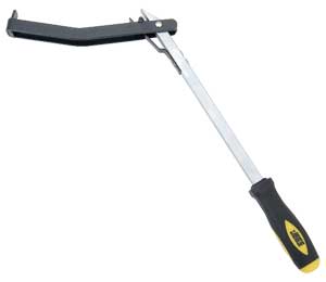
even a correct and very inexpensive tool for spinning it from the flex-plate or flywheel,
once the cylinder heads are installed,
so your not stressing the damper retention bolt spinning the engine over manually,
https://www.summitracing.com/parts/wmr-w80510/overview/
https://www.summitracing.com/parts/sum-900178/overview/
watch the video
http://www.youtube.com/watch?v=YdIGZ-tV ... re=related
http://www.classiccarauto.com/impala/ho ... _tdc.shtml
YOULL WANT THESE TOOLS TO DO IT EASILY
viewtopic.php?f=50&t=417
viewtopic.php?f=50&t=365&p=1094&hilit=+firing+order#p1094
theres the type of piston stop that works with the heads already installed
http://store.summitracing.com/partdetai ... toview=sku
http://store.summitracing.com/partdetai ... toview=sku
How to find TDC and make your own Piston Stop
Posted by John Heard in Fabrication
While putting together the engine and setting up the Jesel Belt Drive, I needed to check Top Dead Center (TDC) and when I went to look for my tool to screw into the spark plug hole, I couldn’t find it. So it was time to make a new one.
Last time I took the trouble to modify an old spark plug knocking out the porcelain, and welding a bolt to the end which was frankly a pain in the ass with the time it takes. Porcelain doesn’t knock out of a spark plug real easy.
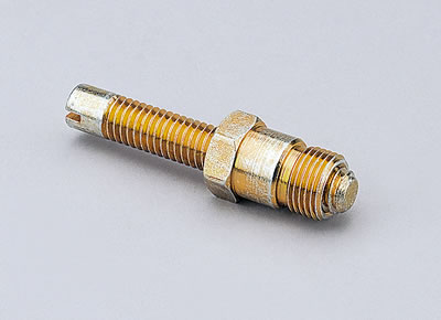
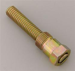
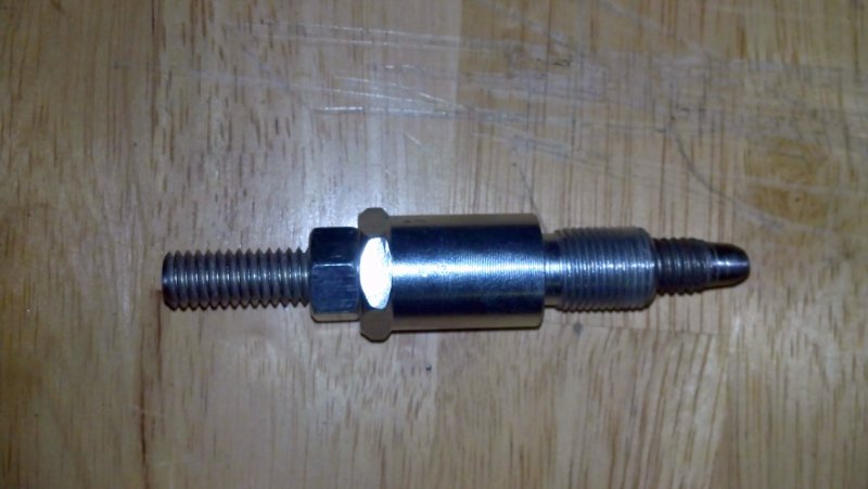
I quick trip to the local O’Rielly’s didn’t turn up a regular tool for this, but I did find some 14mm spark plug anti-foul adapters. These things are made as a spark plug extension (Wonder if they work?), but for this project they work great to modify for a spark plug stop. A big plus is they aren’t very hard, making it somewhat easy to thread a bolt down in it.
I drilled the center out and tapped it for 3/8-16 NC, then got a piece of all-thread and smoothed the nose so it won’t mark the piston. Presto, instant piston stop and it’s easy to make in a few minutes without having to drag the welder out.
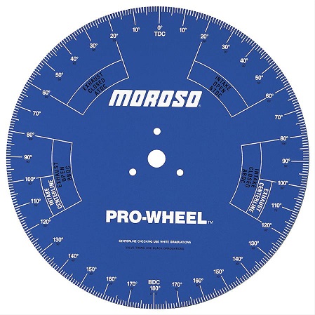
For those that haven’t used one of these before, you screw this into #1 cyl. Then put a degree wheel on the crank, rotate the engine clockwise slowly till it hits the bolt. Then mark the degree wheel where that position is at. Then, rotate the crank counter-clockwise (slowly!) again till it hits the bolt. Mark the degree wheel at this location.
The engine Top Dead Center (TDC) position is half the way between those two locations you marked on the degree wheel.
theres the type of piston stop that works with the heads REMOVED
you can buy a piston deck bridge tool and thread a bolt with two nuts through the center to extend perhaps .060 further than the two feet extend on a flat surface
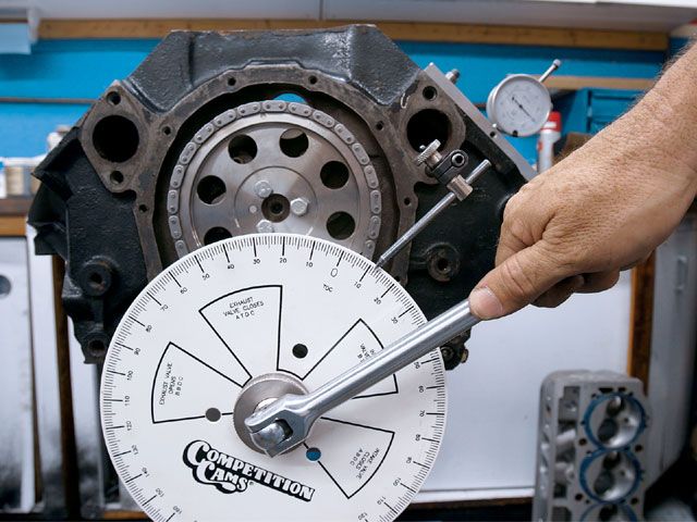
Find Top Dead Center
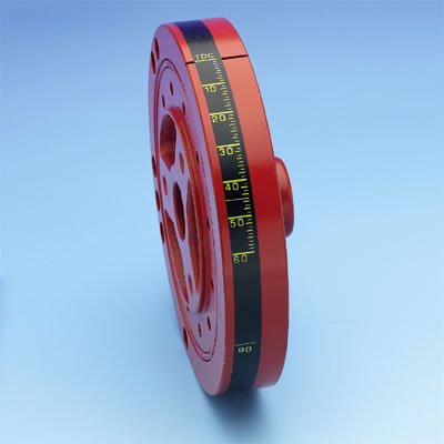
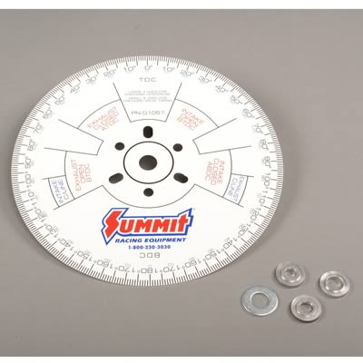
Fasten the degree wheel to the crank.
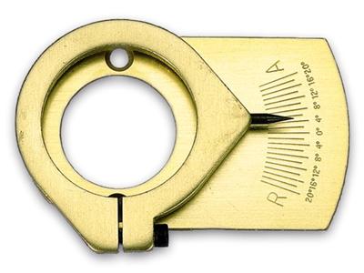
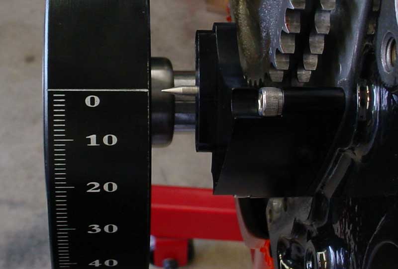
Take a stiff 1/4-inch rod or similar material and sharpen one end to form a pointer.

Attach this pointer so that it rests very close to the damper to eliminate parallax viewing error.
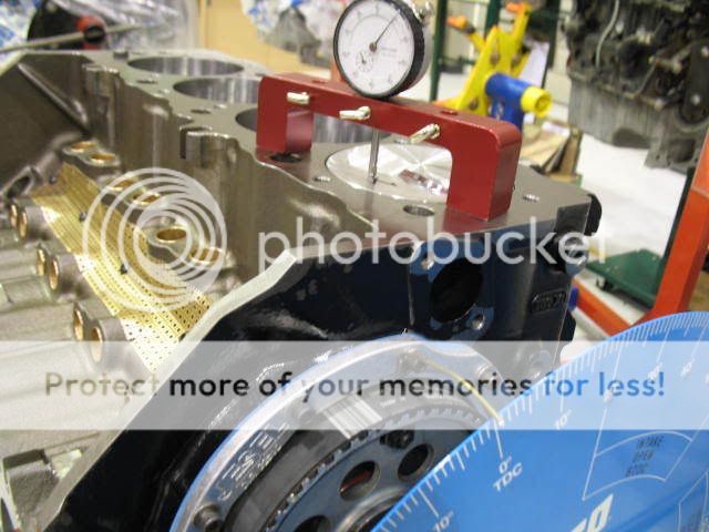
Obtain a stout strip of steel about seven inches long, drill three holes, two for head bolts and one centered on piston.
Put a bolt in the center hole to stop piston movement.
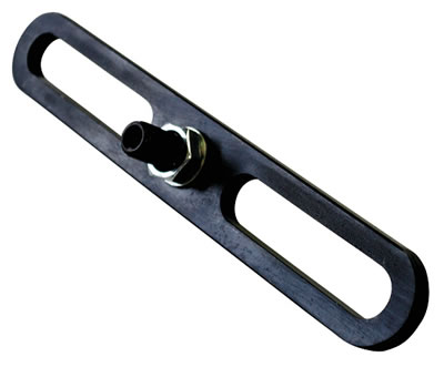
This strip is then placed across the center of No. 1 cylinder bore and bolted on each end to secure it to the block.
Caution: Be sure that the strip of steel is rigid enough so that it will not be deflected when the piston contacts the center bolt stop.
Incidentally, the positive stop should be adjusted so as to stop the rotation the crankshaft in normal running direction (clockwise) until the piston crown lightly strikes this stop.
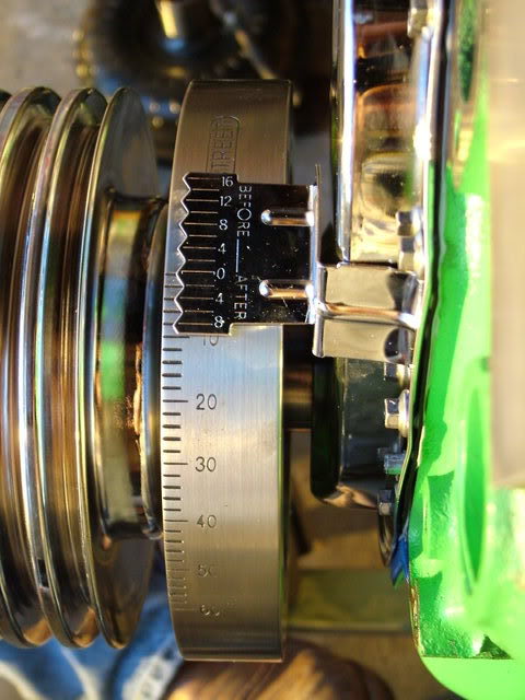
Now, radially turn and lock the degree wheel to the crankshaft at 40 degrees before T.D.C. at the pointer.
Rotate the crankshaft backwards to the positive stop.
If the degree wheel reads 40 degrees from T.D.C. you have hit Top Dead Center exactly, and the zero mark between the two 40 degree readings is absolute T.D.C..
However, if your readings were unbalanced, you will have to split the difference (your errors in degrees) by moving the degree wheel radially on the crankshaft.
Then, try again until you get exactly the same degree readings against the positive stop on either side of T.D.C.
NOTE: The lower the positive stop is located below T.D.C., the greater the degree readings will be.
The results will always be accurate.
T.D.C. always lies equidistant between the two positive stop readings.
or if you can fabricate and weld a short scrap section of 3/4" box steel and a bit of imagination??
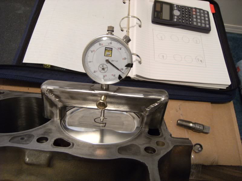
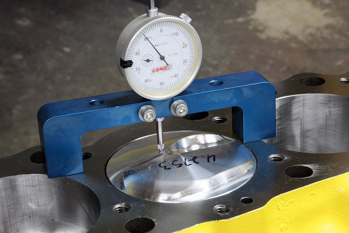
OR YOU COULD USE A BRIDGE AND A DIAL INDICATOR TO LOCATE TDC.
http://www.totalengineairflow.com/tools
http://store.summitracing.com/partdetai ... toview=sku
getting the distributor seated /timing ETC
http://www.pontiacstreetperformance.com/psp/distcurve.html
http://forum.grumpysperformance.com/viewtopic.php?f=52&t=966
http://forum.grumpysperformance.com/viewtopic.php?f=70&t=1015&p=1864&hilit=+tabs#p1864
http://forum.grumpysperformance.com/viewtopic.php?f=50&t=54
http://forum.grumpysperformance.com/viewtopic.php?f=44&t=464
http://forum.grumpysperformance.com/viewtopic.php?f=70&t=1411
step one, pull the #1 plug and place the tip of your finger over the plug hole and rotate the engine until you feel COMPRESSION build as the number one cylinder, piston starts its compression stroke as the mark on the damper gets close to the timing tab, then remove your finger and continue turning the engine until the timing line on the damper aligns with the timing tab (0) TDC
once thats done the engine should not rotate any more until the distributor is seated correctly.
once thats lined up you drop the distributor into the engine so the rotor on the distributor points at the #1 cylinder when it seats and you install and lightly tighten the clamp and connect the wires, connect the timing light and set the timing at about 6-8 degrees BTDC at idle as a start point., if the distributor won,t fully seat the oil pump drive shaft needs to be turned a few degrees with a long large flat blade screw driver and re-try seating it while, it might take several tries until it lines up, it will seat into the distributor base gear once the oil pump drive aligns with the oil pump slot in the distributor gear base
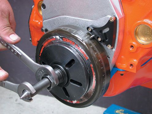
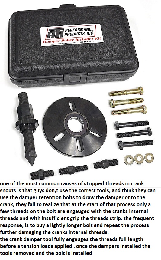
use the correct damper instal tool NEVER beat a damper with a hammer
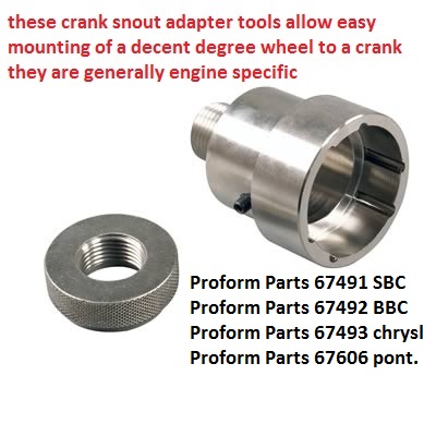
I,ve generally found that if you've stripped the SBC crank snout threads the best answer is to drill and re-thread to the standard and larger BBC crank snout bolt threads size
be aware that some damper designs do tend to fail over time!
beating a balancer onto a crank, pulling it with the wrong type of tool, or letting it get fuel or oil soaked can damage a damper, this can easily result in the outer damper ring with the TDC mark rotating to a random location
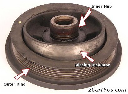
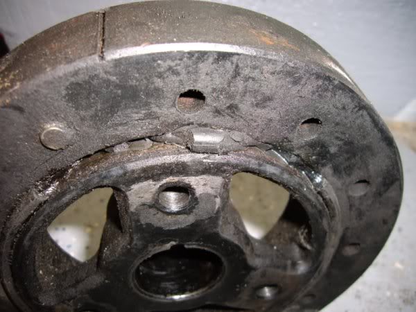
if your front crank seal leaks, over time it can dissolve the elastic, between the inner and outer damper hub weight, beating on a damper tends to hurt the flex ring seal alsos
If your trying to isolate and test and get the engine tune correct, on any efi system,
Id suggest you leave the fuel pressure alone if its at least 40 psi and does not exceed about 58 psi,
and if the fuel pressures consistent, and set the spark plug gap at .043-.045 max and keep th engine coolant temps as consistent and near about 180F-190F as you can get them,
the fewer variable your forced to deal with the better, make the changes in INJECTOR PULSE DURATION and ignition advance curves
to vary the fuel/air ratios and cylinder pressure
to avoid detonation and tuning issues
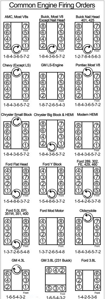
always start by verifying what your dealing with in temps fuel pressure and sensor function, pull trouble codes and read and tuning instructions, get a shop manual and verify sensor functions and electrical connections electrical grounds, ignition firing orders, do a compression test and verify the valve lash, set the valves if that's required, and make sure your not dealing with partially clogged catalytic converter carefully, verify what your dealing with, don,t guess, verify.
I can assure you that most problems are related to guessing or defective sensors, or assuming somethings working, that you fail to verify, like the ohms resistance in ignition wire or the firing order or verifying TDC, vs the damper/timing tabs
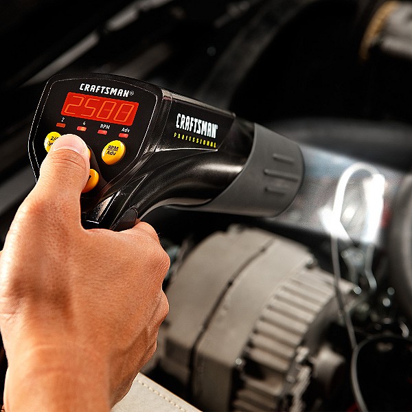
having a set of multi meter/timing light, compression gauge, vacuum and fuel pressure gauges and a shop manual is critical.
http://www.frontiernet.net/~ennis/tdc.html
http://www.2quicknovas.com/2qntdc.html
http://www.corvette-restoration.com/res ... ing101.pdf
viewtopic.php?f=70&t=1015
http://garage.grumpysperformance.com/index.php?threads/finding-top-dead-center.967/
http://garage.grumpysperformance.co...ter-1-for-timing-ignition-cam.966/#post-18999
http://garage.grumpysperformance.co...evy-damper-is-designed-for-your-engine.11561/
these threads might help
step one
remove ALL the spark plugs,IN ALL CYLINDERS, and make sure the cars not in gear,
so spinning the engine over manually is far less effort and feeling the piston touch, the piston stop is much easier.
remove both rockers from that cylinder during the process of verifying TDC
BTW I assume you gentlemen do know theres
even a correct and very inexpensive tool for spinning it from the flex-plate or flywheel,
once the cylinder heads are installed,
so your not stressing the damper retention bolt spinning the engine over manually,
https://www.summitracing.com/parts/wmr-w80510/overview/
https://www.summitracing.com/parts/sum-900178/overview/
watch the video
http://www.youtube.com/watch?v=YdIGZ-tV ... re=related
http://www.classiccarauto.com/impala/ho ... _tdc.shtml
YOULL WANT THESE TOOLS TO DO IT EASILY
viewtopic.php?f=50&t=417
viewtopic.php?f=50&t=365&p=1094&hilit=+firing+order#p1094
theres the type of piston stop that works with the heads already installed
http://store.summitracing.com/partdetai ... toview=sku
http://store.summitracing.com/partdetai ... toview=sku
How to find TDC and make your own Piston Stop
Posted by John Heard in Fabrication
While putting together the engine and setting up the Jesel Belt Drive, I needed to check Top Dead Center (TDC) and when I went to look for my tool to screw into the spark plug hole, I couldn’t find it. So it was time to make a new one.
Last time I took the trouble to modify an old spark plug knocking out the porcelain, and welding a bolt to the end which was frankly a pain in the ass with the time it takes. Porcelain doesn’t knock out of a spark plug real easy.
I quick trip to the local O’Rielly’s didn’t turn up a regular tool for this, but I did find some 14mm spark plug anti-foul adapters. These things are made as a spark plug extension (Wonder if they work?), but for this project they work great to modify for a spark plug stop. A big plus is they aren’t very hard, making it somewhat easy to thread a bolt down in it.
I drilled the center out and tapped it for 3/8-16 NC, then got a piece of all-thread and smoothed the nose so it won’t mark the piston. Presto, instant piston stop and it’s easy to make in a few minutes without having to drag the welder out.
For those that haven’t used one of these before, you screw this into #1 cyl. Then put a degree wheel on the crank, rotate the engine clockwise slowly till it hits the bolt. Then mark the degree wheel where that position is at. Then, rotate the crank counter-clockwise (slowly!) again till it hits the bolt. Mark the degree wheel at this location.
The engine Top Dead Center (TDC) position is half the way between those two locations you marked on the degree wheel.
theres the type of piston stop that works with the heads REMOVED
you can buy a piston deck bridge tool and thread a bolt with two nuts through the center to extend perhaps .060 further than the two feet extend on a flat surface
Find Top Dead Center
Fasten the degree wheel to the crank.
Take a stiff 1/4-inch rod or similar material and sharpen one end to form a pointer.
Attach this pointer so that it rests very close to the damper to eliminate parallax viewing error.
Obtain a stout strip of steel about seven inches long, drill three holes, two for head bolts and one centered on piston.
Put a bolt in the center hole to stop piston movement.
This strip is then placed across the center of No. 1 cylinder bore and bolted on each end to secure it to the block.
Caution: Be sure that the strip of steel is rigid enough so that it will not be deflected when the piston contacts the center bolt stop.
Incidentally, the positive stop should be adjusted so as to stop the rotation the crankshaft in normal running direction (clockwise) until the piston crown lightly strikes this stop.
Now, radially turn and lock the degree wheel to the crankshaft at 40 degrees before T.D.C. at the pointer.
Rotate the crankshaft backwards to the positive stop.
If the degree wheel reads 40 degrees from T.D.C. you have hit Top Dead Center exactly, and the zero mark between the two 40 degree readings is absolute T.D.C..
However, if your readings were unbalanced, you will have to split the difference (your errors in degrees) by moving the degree wheel radially on the crankshaft.
Then, try again until you get exactly the same degree readings against the positive stop on either side of T.D.C.
NOTE: The lower the positive stop is located below T.D.C., the greater the degree readings will be.
The results will always be accurate.
T.D.C. always lies equidistant between the two positive stop readings.
or if you can fabricate and weld a short scrap section of 3/4" box steel and a bit of imagination??
OR YOU COULD USE A BRIDGE AND A DIAL INDICATOR TO LOCATE TDC.
http://www.totalengineairflow.com/tools
http://store.summitracing.com/partdetai ... toview=sku
getting the distributor seated /timing ETC
http://www.pontiacstreetperformance.com/psp/distcurve.html
http://forum.grumpysperformance.com/viewtopic.php?f=52&t=966
http://forum.grumpysperformance.com/viewtopic.php?f=70&t=1015&p=1864&hilit=+tabs#p1864
http://forum.grumpysperformance.com/viewtopic.php?f=50&t=54
http://forum.grumpysperformance.com/viewtopic.php?f=44&t=464
http://forum.grumpysperformance.com/viewtopic.php?f=70&t=1411
step one, pull the #1 plug and place the tip of your finger over the plug hole and rotate the engine until you feel COMPRESSION build as the number one cylinder, piston starts its compression stroke as the mark on the damper gets close to the timing tab, then remove your finger and continue turning the engine until the timing line on the damper aligns with the timing tab (0) TDC
once thats done the engine should not rotate any more until the distributor is seated correctly.
once thats lined up you drop the distributor into the engine so the rotor on the distributor points at the #1 cylinder when it seats and you install and lightly tighten the clamp and connect the wires, connect the timing light and set the timing at about 6-8 degrees BTDC at idle as a start point., if the distributor won,t fully seat the oil pump drive shaft needs to be turned a few degrees with a long large flat blade screw driver and re-try seating it while, it might take several tries until it lines up, it will seat into the distributor base gear once the oil pump drive aligns with the oil pump slot in the distributor gear base
use the correct damper instal tool NEVER beat a damper with a hammer
I,ve generally found that if you've stripped the SBC crank snout threads the best answer is to drill and re-thread to the standard and larger BBC crank snout bolt threads size
be aware that some damper designs do tend to fail over time!
beating a balancer onto a crank, pulling it with the wrong type of tool, or letting it get fuel or oil soaked can damage a damper, this can easily result in the outer damper ring with the TDC mark rotating to a random location
if your front crank seal leaks, over time it can dissolve the elastic, between the inner and outer damper hub weight, beating on a damper tends to hurt the flex ring seal alsos
If your trying to isolate and test and get the engine tune correct, on any efi system,
Id suggest you leave the fuel pressure alone if its at least 40 psi and does not exceed about 58 psi,
and if the fuel pressures consistent, and set the spark plug gap at .043-.045 max and keep th engine coolant temps as consistent and near about 180F-190F as you can get them,
the fewer variable your forced to deal with the better, make the changes in INJECTOR PULSE DURATION and ignition advance curves
to vary the fuel/air ratios and cylinder pressure
to avoid detonation and tuning issues
always start by verifying what your dealing with in temps fuel pressure and sensor function, pull trouble codes and read and tuning instructions, get a shop manual and verify sensor functions and electrical connections electrical grounds, ignition firing orders, do a compression test and verify the valve lash, set the valves if that's required, and make sure your not dealing with partially clogged catalytic converter carefully, verify what your dealing with, don,t guess, verify.
I can assure you that most problems are related to guessing or defective sensors, or assuming somethings working, that you fail to verify, like the ohms resistance in ignition wire or the firing order or verifying TDC, vs the damper/timing tabs
having a set of multi meter/timing light, compression gauge, vacuum and fuel pressure gauges and a shop manual is critical.
Last edited by a moderator: