Mark Bradley
Da guy in Newbury
I was involved in a accident and it made me think about a few things differently.
The motor kept running until I shut it off.
Why that is key is that my EFI would continue to drive the fuel pump as long as it sees a tach signal.
The modern electric fuel pumps can drain a tank pretty quick and while I did not have a fire I questioned what would have been the outcome if I did.
This is why I built a fuel cut off circuit that will disrupt the pump if the line pressure drops below a preset trigger.
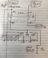
Looking at the hand drawing as the guide...
FiTech supplies the “engine run” trigger (power) and is applied to the pin 86 on R1 relay.
(You could also use then coil power or fuse panel ACC tab.)
Pin 85 of R1 needs a ground to complete the circuit and energize the high current side (pin 30 to 87) of the relay thus driving the fuel pump.
Pin 85 of R1 gets a conditional ground state from one of two sources:
Momentary ground conditions (R2):
VCC of R2 has power at “key-on” (maybe FiTech orange, coil or ACC)and the GND pin is chassis ground. Energizing R2 closes the current circuit (load side) bridging the pin 85 of R1 to ground via the “common” terminal of R2.
The effect of this will be providing ground to the trigger circuit for R1(until the R2 timer expires) thus completing the R1 (pin 30 to 87) circuit driving the fuel pump and presumably building fuel line pressure.
Presumably SW1 will have closed as pressure Built.
As the R2 timer logic expires it will open its load circuit thus cutting the momentary ground signal for R1
Fuel pressure switch (SW1):
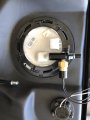
In parallel to R2 is an adjustable normally open fuel pressure switch monitoring the fuel supply line.
As the line pressure reaches a set point (TBD) the contacts will close and complete a redundant ground path for the R1 trigger circuit allowing the fuel pump to continue running when the R2 timer expires.
Loss of fuel pressure:
If the fuel pressure was to drop unexpectedly the pressure switch would return to an open state and the fuel pump would stop running.
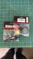
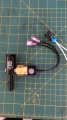
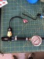
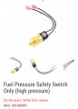
Adjustable Fuel Pressure Switch (Normally Open)
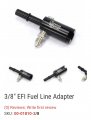
Fuel line adapter for the switch
Function Testing:
Key-on will supply power for a duration programmed into the ECU and perform the initial unit prime.
If there is no RPM signal in X seconds the ECU will stop supplying power.
Verify that R1 does not have ground at Key Off.
Testing the digital relay (R2).
Remove the connections to the pressure switch circuit.
Key-on then verify the relay provides ground for R1 and R1 energies.
R1 should shut off after R2 times out with SW1 open.
Jumper SW1 to mimic line pressure.
Replete the previous test and ensure ground remains at all times.
Power will die because the FiTech cuts power when it does not see rpm.
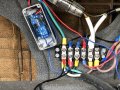
I’ll post a number of photos and notes for review although it has been in place for about 2 months and I have had zero problems yet and I did actually test it while the car was running.. worked great.

The motor kept running until I shut it off.
Why that is key is that my EFI would continue to drive the fuel pump as long as it sees a tach signal.
The modern electric fuel pumps can drain a tank pretty quick and while I did not have a fire I questioned what would have been the outcome if I did.
This is why I built a fuel cut off circuit that will disrupt the pump if the line pressure drops below a preset trigger.
Looking at the hand drawing as the guide...
FiTech supplies the “engine run” trigger (power) and is applied to the pin 86 on R1 relay.
(You could also use then coil power or fuse panel ACC tab.)
Pin 85 of R1 needs a ground to complete the circuit and energize the high current side (pin 30 to 87) of the relay thus driving the fuel pump.
Pin 85 of R1 gets a conditional ground state from one of two sources:
- A momentary ground via a timer/relay
- A pressure switch closed by adequate fuel pressure.
Momentary ground conditions (R2):
VCC of R2 has power at “key-on” (maybe FiTech orange, coil or ACC)and the GND pin is chassis ground. Energizing R2 closes the current circuit (load side) bridging the pin 85 of R1 to ground via the “common” terminal of R2.
The effect of this will be providing ground to the trigger circuit for R1(until the R2 timer expires) thus completing the R1 (pin 30 to 87) circuit driving the fuel pump and presumably building fuel line pressure.
Presumably SW1 will have closed as pressure Built.
As the R2 timer logic expires it will open its load circuit thus cutting the momentary ground signal for R1
Fuel pressure switch (SW1):
In parallel to R2 is an adjustable normally open fuel pressure switch monitoring the fuel supply line.
As the line pressure reaches a set point (TBD) the contacts will close and complete a redundant ground path for the R1 trigger circuit allowing the fuel pump to continue running when the R2 timer expires.
Loss of fuel pressure:
If the fuel pressure was to drop unexpectedly the pressure switch would return to an open state and the fuel pump would stop running.
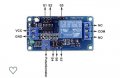
- Example circuitry below
- R2 details below:
- 2.2” long x 1.16”
Adjustable Fuel Pressure Switch (Normally Open)
Fuel line adapter for the switch
Function Testing:
Key-on will supply power for a duration programmed into the ECU and perform the initial unit prime.
If there is no RPM signal in X seconds the ECU will stop supplying power.
Verify that R1 does not have ground at Key Off.
Testing the digital relay (R2).
Remove the connections to the pressure switch circuit.
Key-on then verify the relay provides ground for R1 and R1 energies.
R1 should shut off after R2 times out with SW1 open.
Jumper SW1 to mimic line pressure.
Replete the previous test and ensure ground remains at all times.
Power will die because the FiTech cuts power when it does not see rpm.
I’ll post a number of photos and notes for review although it has been in place for about 2 months and I have had zero problems yet and I did actually test it while the car was running.. worked great.
Attachments
-
 C9111C4C-FC54-4988-B0D4-9D06AEADB86B.jpeg205.3 KB · Views: 25
 -
 3B002A90-0C41-4760-BEC4-A6C8119DABE1.jpeg118.7 KB · Views: 4
 -
 6D908AC2-A857-4F48-A4DA-E97209F60E10.jpeg120.9 KB · Views: 3
 -
 1068F475-99C1-4785-B50C-3D43B6DE6D59.jpeg184.3 KB · Views: 3
 -
 20D48256-D8C2-46C8-9F47-132A6F4BAA04.jpeg110.8 KB · Views: 3
 -
 35291083-A7AF-4EA0-B153-F2427E91ECBC.jpeg277.4 KB · Views: 3
 -
 F31AD5B5-0452-41DC-8B64-7105AF56F7AB.jpeg71.6 KB · Views: 3
 -
 AD706719-BA56-4C69-9E62-3F1041976B5F.jpeg162 KB · Views: 3
 -
 90CA417A-5322-4E05-888C-D81428CB35F0.jpeg85.1 KB · Views: 3
Last edited by a moderator:

