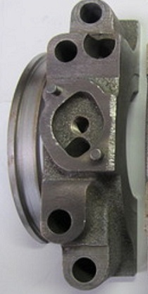
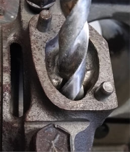
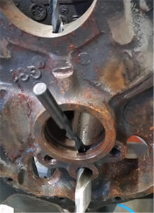
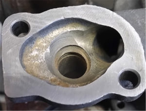
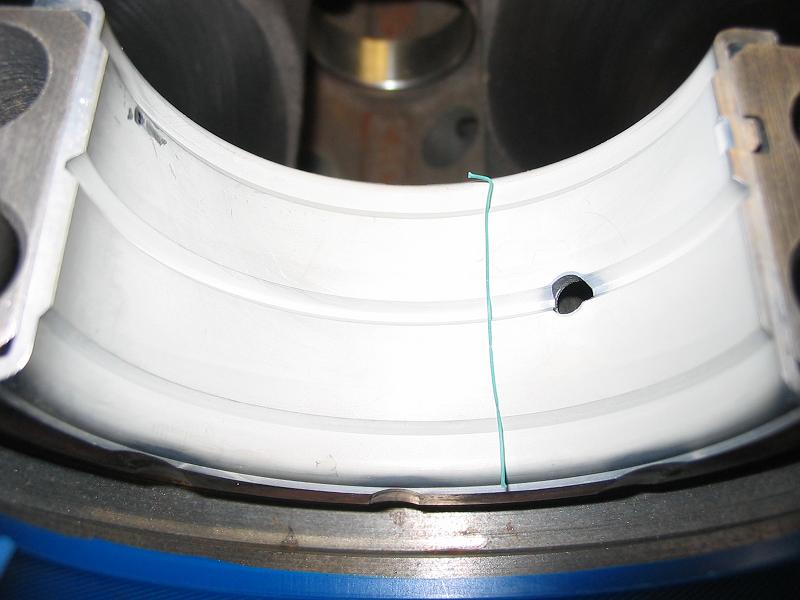
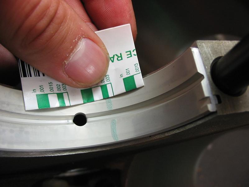
lining up oil feed holes in bearings shells

grumpyvette

Administrator
Staff member
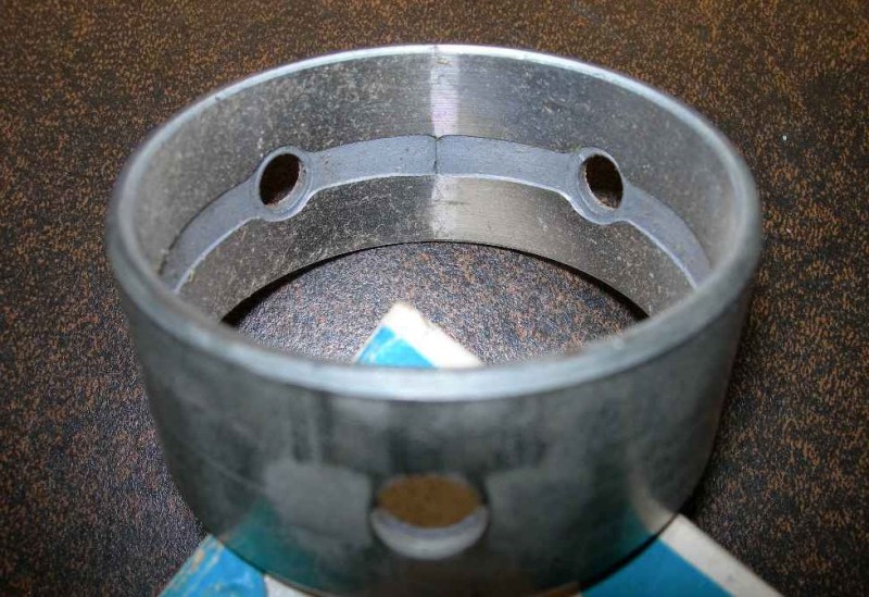
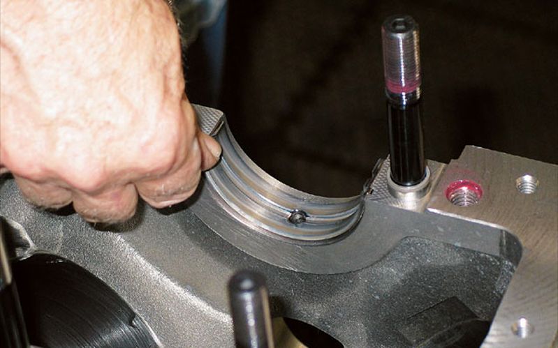
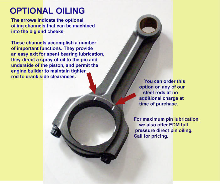
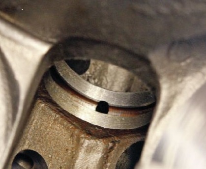
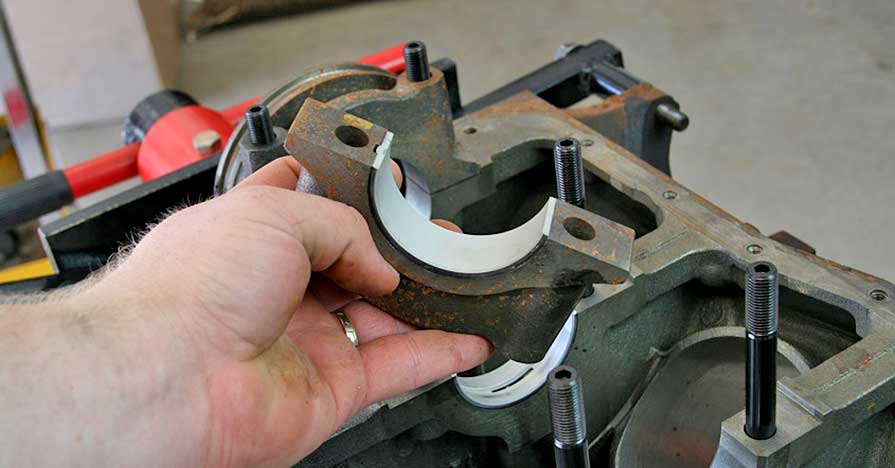
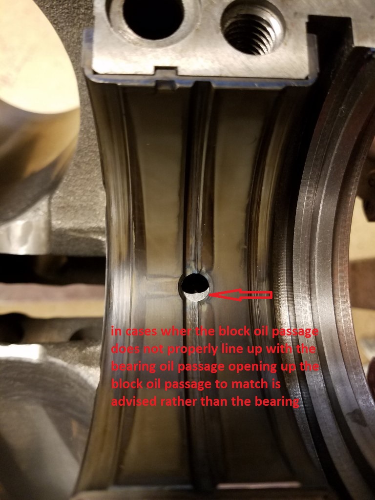
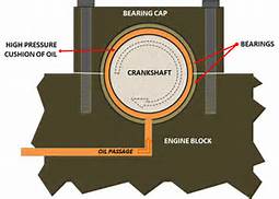
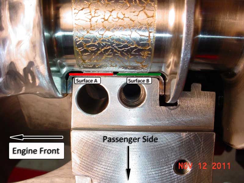
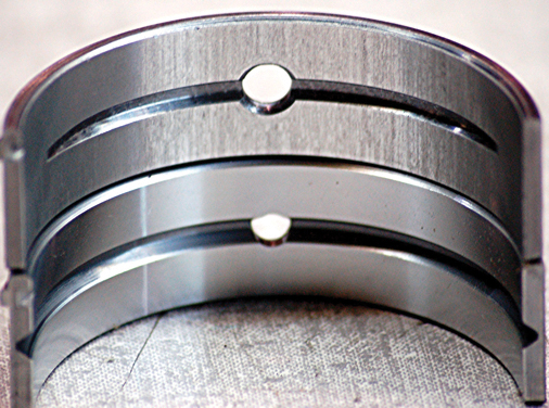
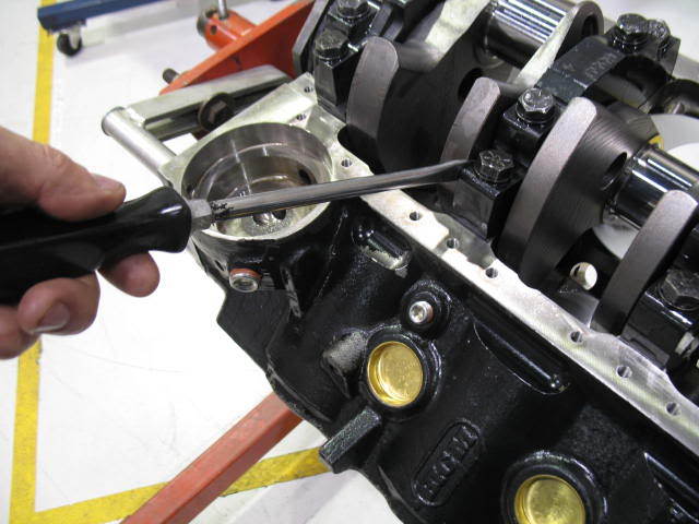
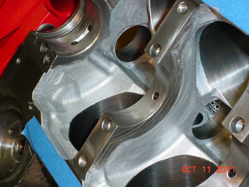
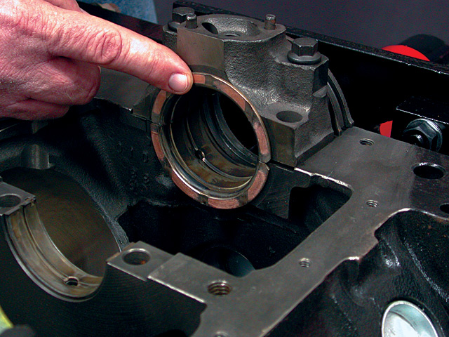
I just got an e-mail asking what to do if you find that the blocks oil feed passage holes don,t line up exactly right with the holes in the oil feed holes in bearings shells?

painted2.jpg

umain1.jpg


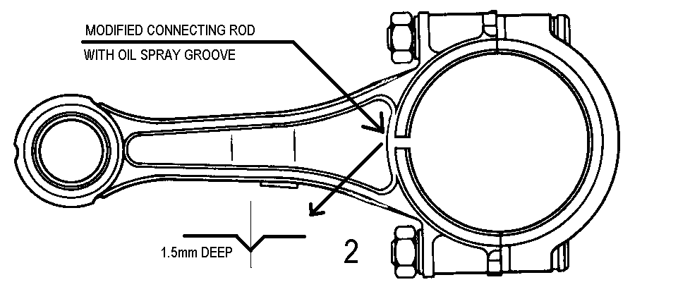
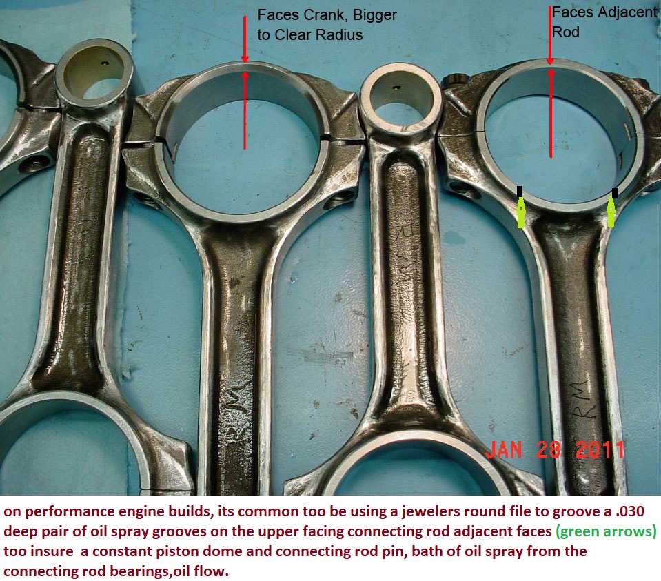
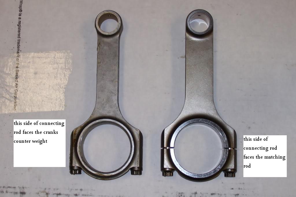
rodoil1.jpg

rodoil2.gif

rodoil3.jpg

rodoil4.jpg

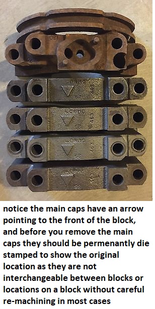
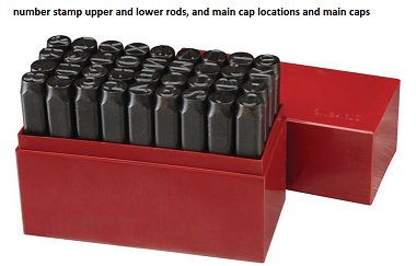
paint, marker etc. tends to wash off, you really should lightly die stamp the main caps
454-502-BBC-4-Bolt-Main-Caps.jpg

https://www.harborfreight.com/36-pi...mping-set-63675.html?_br_psugg_q=number+stamp

63675_I.jpg

well different manufacturers have different bearings and you may want to find a different brand or part number bearing before you go to the effort too modifying any component or the block, but I generally use CLEVITE (H) series bearings and I usually find and off set is minimal.
I;ve rarely seen the oil feed passages off by more than 1/16" but Ive heard of them being off by 1/8" with some bearing sets, and know that with some other engines than the BBC, SBC, and PONTIAC engines I generally build they can be much further off.
since blocks are cast and the machining is done indexed off the crank center line the oil passage locations tend to be very slightly different in each block casting.
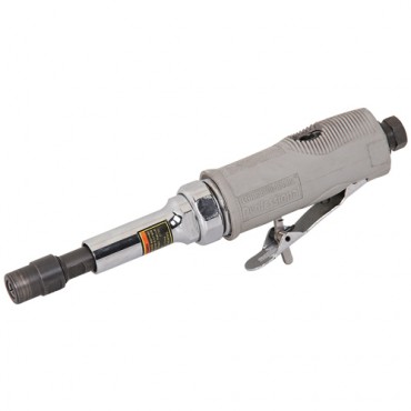
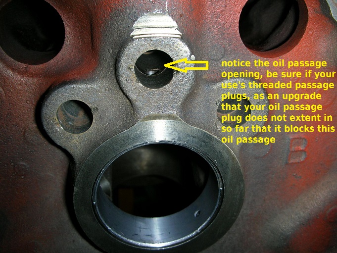
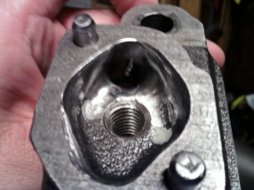
the option youll generally have is to either open up the passage in the block to match the bearing shell which is generally the route most guys will take if the off set is minimal by running a counter sink bit into the opening in the oil feed passage or by using a dremel, or die grinder tool with a burr to elongate the opening on only one side to match the bearings oil feed hole.
you generally won,t do much to the bearing shell itself other than in some limited cases opening the oil feed hole slightly if its in the lower groove in an upper main cap bearing as bearings are fairly easy to distort.

14653.jpg
55798-01-200.jpg

nozzle.gif

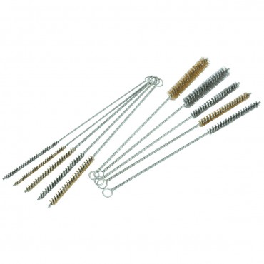
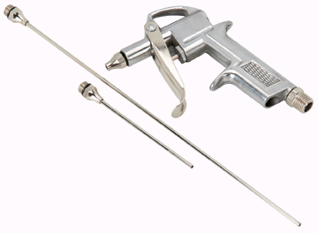
if you are forced to make minor changes Id suggest blocking the oil feed passage with a bit of paraffin wax then carefully cleaning after wards with a rifle bore brush, high pressure air and solvent, paraffin wax has the advantage of melting into a harmless liquid that will mix with oil if a small amounts left UN-intentionally in an oil passage
image_4278.jpg


http://www.hotrod.com/how-to/engine/181 ... g-install/

http://garage.grumpysperformance.com/index.php?threads/bearing-clearances.2726/#post-7077

http://garage.grumpysperformance.co...hrust-bearing-failure-info-related-info.1138/

http://garage.grumpysperformance.com/index.php?threads/causes-of-bearing-failure.2727/#post-13056

http://garage.grumpysperformance.com/index.php?threads/bearing-clearances.2726/#post-7077

http://garage.grumpysperformance.com/index.php?threads/bearing-clearances.2726/#post-26599

http://garage.grumpysperformance.com/index.php?threads/rotating-assembly-bearings.9527/

viewtopic.php?f=54&t=52

http://thmotorsports.com/clevite_77/cle ... 62379.aspx
 
Last edited by a moderator:
http://kingracebearings.com/wp-cont...-oil-groove-for-high-performance-bearings.pdf
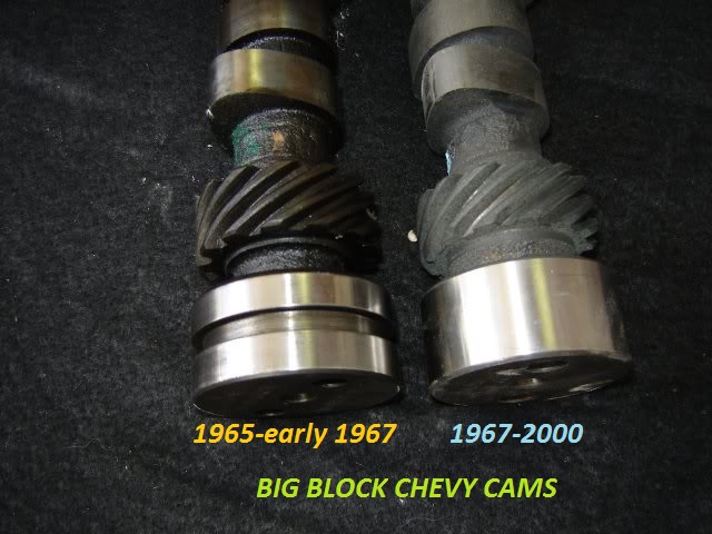
IT helps to know exactly what year and casting number your engine block is as early production big block engines used a different rear cam bearing and cam, a potential rear cam bearing oil flow issue is found on the 1965- too a few very early 1967 engines ,if you install the older design BBC cam with a grooved rear main in EITHER config with EITHER rear bearing your covered, and since thats just not expensive and any decent machine shop can modify any cam like that cheaply is the smart route to take if your in doubt. obviously having the machine shop groove the rear cam journal under the cam bearing in the block like the later BBC engines would be ideal.
YES READING LINKS WILL HELP A GREAT DEAL

http://garage.grumpysperformance.com/index.php?threads/thrust-bearing-wear.619/

http://garage.grumpysperformance.com/index.php?threads/precision-measuring-tools.1390/#post-68861


http://garage.grumpysperformance.com/index.php?threads/bearing-clearances.2726/

http://garage.grumpysperformance.co...ed-holes-in-bearings-shells.10750/#post-53298

http://garage.grumpysperformance.com/index.php?threads/precision-measuring-tools.1390/#post-44530


http://garage.grumpysperformance.com/index.php?threads/which-torque-wrench.342/#post-10864


SKIPPING READING THE LINKS IS GENERALLY GOING TO BE A MISTAKE
http://www.superchevy.com/how-to/engines-drivetrain/4380-bearing-clearance-info/

https://www.chevyhardcore.com/tech-...ies-measuring-and-setting-bearing-clearances/

https://www.chevydiy.com/pre-assembly-guide-build-chevy-small-block-engines/

http://knowhow.napaonline.com/know-notes-measure-engine-bearing-clearance/

https://www.mahle-aftermarket.com/media/local-media-north-america/pdfs-&-thumbnails/cl77-1-205r.pdf

http://www.superchevy.com/how-to/engines-drivetrain/0707ch-main-bearing-clearance/

https://www.enginebuildermag.com/2013/03/bearing-clearances/

https://blog.k1technologies.com/how-to-check-bearing-clearances


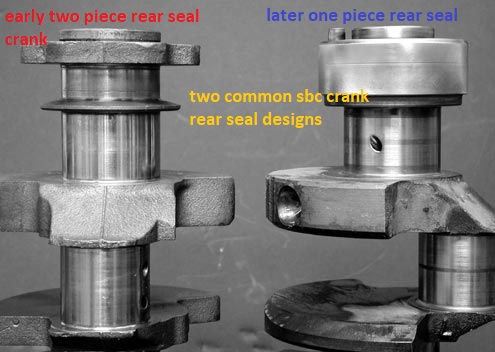
crankse.jpg

camjournal.jpg

1965396CamOilGroovea.jpg

http://garage.grumpysperformance.com/index.php?threads/cam-bearing-install-tools-install-info.1479/


http://garage.grumpysperformance.co...k-after-a-cam-lobe-rod-or-bearings-fail.2919/

http://garage.grumpysperformance.com/index.php?threads/cam-wear-articles-you-need-to-read.282/
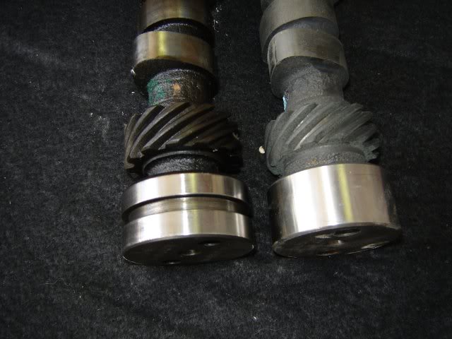
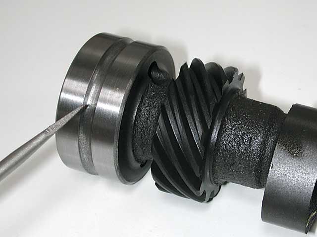
the 1965 and 1966 big block 396 had unique rear cam bearings and required a grooved rear cam journal, most cams you buy currently are not grooved, the groove can be cut on a lathe in the last rear journal on the later cams , centered ,and its about .188 wide and .125 deep, if the cam is cut,for that oil groove the standard cam bearing can be used
camjournal.jpg

1965396CamOilGroove.jpg

groovedcambearing.jpg

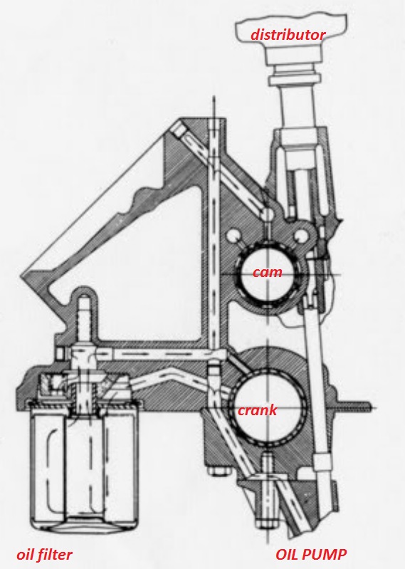
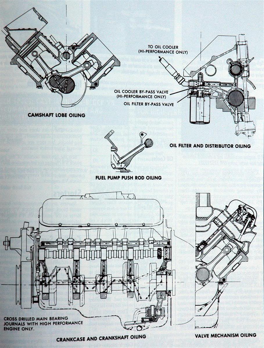
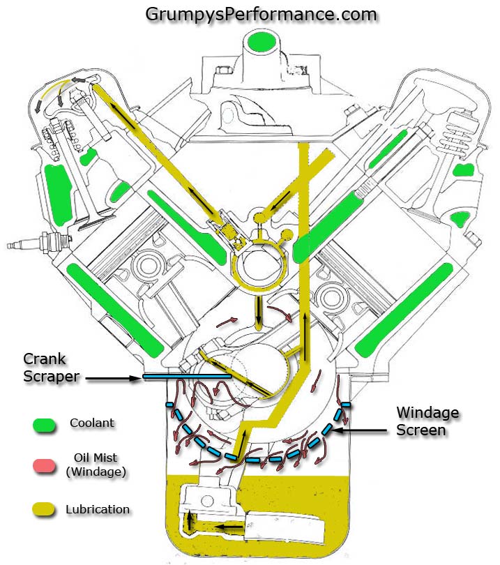
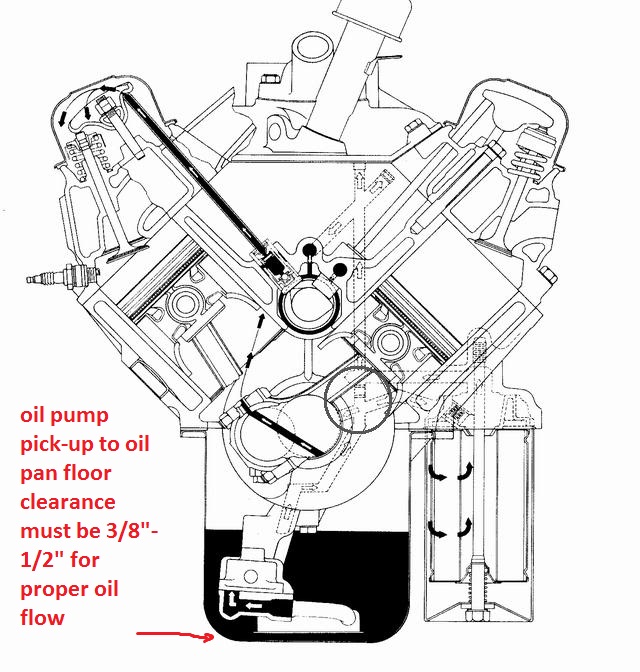
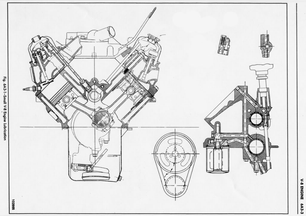
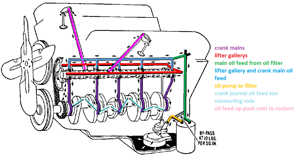
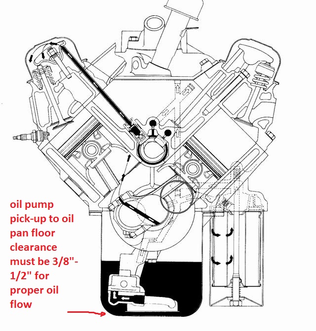
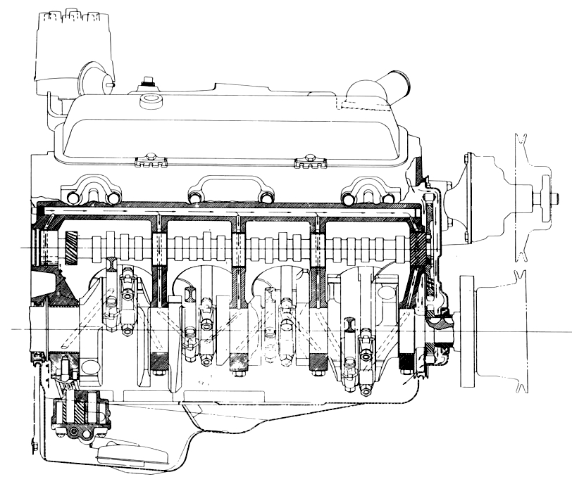
this is a diagram of the big block chevy oil passage system, its designed to feed that rear cam bearing in the center, the groove in the rear cam journal forms the walls of the oil passage cutting an additional groove, in front of the rear freeze plug behind the back cam bearing in the rear of the last cam bearing is unlikely to hurt or help as long as that groove is cut in the cam journal, I've always just cut the groove in the rear cam journal on the 65-66 engines and never had any issues, in fact I know several guys who do that mod on later engines that don,t require it, because they think it helps maintain slightly better oil flow rates to cool the valve train.
OBVIOUSLY if you want too test you manually prime the oil pump ,if you get decent oil flow volume at all the rockers,priming the engine oil pump manually, then obviously the oil flow leaving the pump reaches the intended areas and the route it takes while a bit different than originally designed may still work and not cause you any issues, keep in mind that as the engine rpms increase the oil flow rate needs to the valve train need to increase also and while it may be possible, to machine a shallow groove, in a later rear cam bearing it won,t be able to allow nearly the required oil flow rate at higher rpms as the rear bearing shell is just not thick enough,to allow a deep enough groove on the early engines, those engines, require the early rear cam bearing with the three hole aligned correctly and the grooved rear cam journal, some shops will modify the later cam bearings, installed in early blocks by cutting a large bevel in the rear edge, to allow oil to flow behind and around the rear cam journal, this is not always 100% successful, at providing full oil flow capacity on the early engines that don,t have the block grooved under the rear cam bearing ,especially at higher rpm levels.

read through these links
http://garage.grumpysperformance.com/index.php?threads/metal-in-oil.10875/#post-47688

http://garage.grumpysperformance.co...ilter-you-sellect-does-make-a-differance.117/

http://garage.grumpysperformance.com/index.php?threads/oil-filters.11189/

http://garage.grumpysperformance.co...g-up-oil-feed-holes-in-bearings-shells.10750/


http://garage.grumpysperformance.co...k-after-a-cam-lobe-rod-or-bearings-fail.2919/

http://garage.grumpysperformance.co...g-up-oil-feed-holes-in-bearings-shells.10750/

http://garage.grumpysperformance.com/index.php?threads/oil-system-mods-that-help.2187/


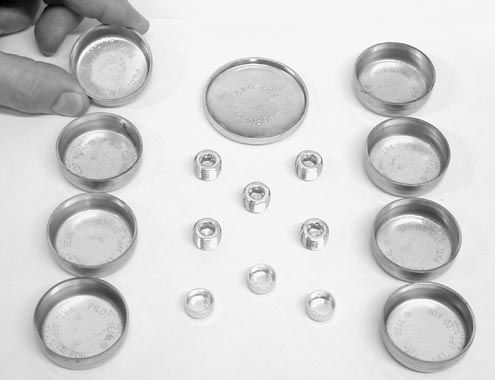
moroso sells plug kits
plugkit.jpg

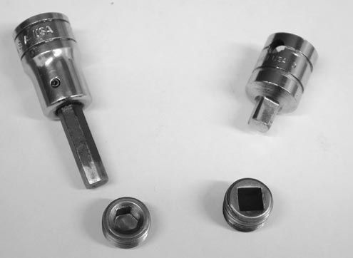
pluginstall.jpg

drillplug.jpg

frontgroove.JPG

http://garage.grumpysperformance.com/index.php?threads/basic-info-on-your-v8-lube-system.52/

sbcoilh5a.jpg

SBCOilingnew.png


ChevyOilingPluga.jpg

sbcoilh1.jpg


sbcoilh6a.jpg


passplug.png


oilpasblc.jpg


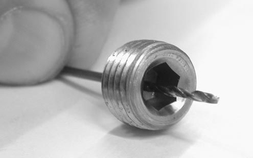
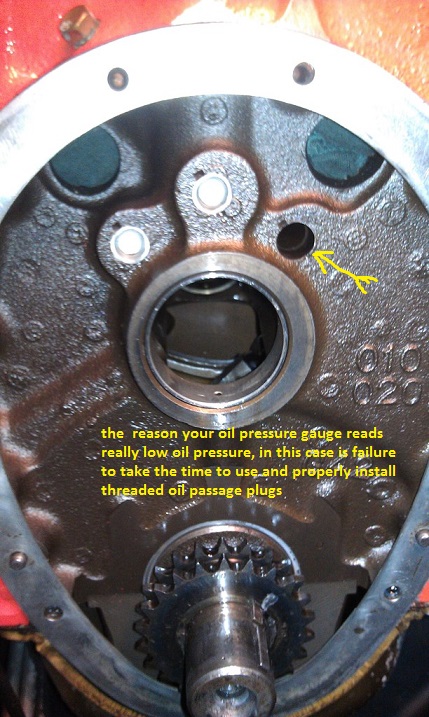
be sure only one oil passage plugs drilled, generally only the pass side oil passage plug with a single .025-.030 hole, many guys use a 1/32" drill bit because its easy to locate, I prefer the smaller #72 drill
IMAG0096pl.jpg


http://buydrillbits.com/products/hss/gp2.php?c=AIR

blockdrill.png

http://www.victornet.com/subdepartments/HS-Long-Drills/1180.html


Cam Bore: 2.140 inches (number-1), 2.130 inches (number-2 and number-5), 2.120 inches (number-3 and number-4); cam bearing inside diameter: 1.950 inches

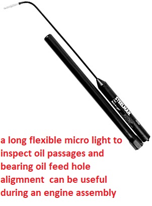
at times having a long small diameter light that you can stick through the blocks oil passages to check the oil feed to the bearings passage alignment helps

STE10150A.jpg


https://www.tooltopia.com/steelman-...MI4s7coYzY2AIV3I2zCh3U6AFUEAQYAiABEgI0PfD_BwE


just wondering , how many of you gentlemen are like I am,
and have taken to keeping a spare set of 275/300 power, reading glasses ,
you pick up from the local dollar store for $1.50 each
300gl.jpg

(I buy several every time I visit and leave a few in the tool box)
and around the shop, and my computer desk,
to read fine print on prescription bottles, component install instructions,
and simply so I can read the dial indicator,
torque wrench, caliper's , micrometers, bore gauges, and similar tools,
and look over the condition of parts, etc,
its AMAZING how much clearer the fine surface finish,
on parts your working on, is,
and fine print is once you have access to clear vision and bright lighting

Ive also found I can use a handy portable light.

biglarry.jpg


https://www.amazon.com/Nebo-Big-Lar...ocphy=9012039&hvtargid=pla-422733965918&psc=1

Chevy V8 bore & stroke chart

Chevy V8 Crankshaft Journal Sizes

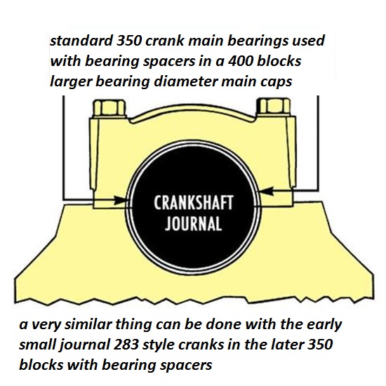
Here's a list of Chevy V-8 crankshaft journal sizes. All journal sizes are given in "STANDARD" sizes. Your crankshaft may have been cut down in size previously by a machine shop. Make sure your crank will work in the block you have. Blocks were made for each crank main journal size. If you are putting a "small" or "medium" journal smallblock crank into a "medium" or "large" journal smallblock block you will need crank bearing "spacers" or use special "thick" bearings available from aftermarket suppliers.

Chevy Smallblock V8 Crankshaft Journal Sizes


Gen.I, "Small Journal"
265...Mains-2.30"-Rods-2.00"
283...Mains-2.30"-Rods-2.00"
302...Mains-2.30"-Rods-2.00"
327...Mains-2.30"-Rods-2.00"


Gen.I, "Medium Journal", includes "Vortec" 305 and 350 thru '98
262...Mains-2.45"-Rods-2.10"
267...Mains-2.45"-Rods-2.10"
302...Mains-2.45"-Rods-2.10"
305...Mains-2.45"-Rods-2.10"
307...Mains-2.45"-Rods-2.10"
327...Mains-2.45"-Rods-2.10"
350...Mains-2.45"-Rods-2.10"


Gen.I, "Large Journal"
400...Mains-2.65"-rods-2.10"


Non-production Gen.I combination, using Gen.I 400 crank in Gen.I 350 block
383...400 crank, Mains cut to 2.45"-Rods-2.10"


Non-production Gen.I combination, using Gen.I 350 crank in Gen.I 400 block
377..."Spacer" or "thick" main bearings with 350 crank-Rods-2.10"


Gen.II, "Medium Journal", includes "L-99" 265, "LT-1" 350, "LT-4" 350
265...Mains-2.45"-rods-2.10"
305...Mains-2.45"-Rods-2.10"
350...Mains-2.45"-Rods-2.10"


Non-production Gen.II combination, using Gen.II 265 "L-99" crank in Gen.II 350 block
302...Mains-2.45"-Rods-2.10"


Gen.III, includes '97-2005 "LS-1" Corvette, Firebird, Camaro
345...Mains-2.558"-Rods-2.10"


Corvette "ZR-1", DOHC, "LT-5"
350...Mains-2.76"-Rods-2.10"

CID BORE STROKE
262 = 3.671" x 3.10" (Gen. I, 5.7" rod)
265 = 3.750" x 3.00" ('55-'57 Gen.I, 5.7" rod)
265 = 3.750" x 3.00" ('94-'96 Gen.II, 4.3 liter V-8 "L99", 5.94" rod)
267 = 3.500" x 3.48" (Gen.I, 5.7" rod)
283 = 3.875" x 3.00" (Gen.I, 5.7" rod)
293 = 3.779" x 3.27" ('99-later, Gen.III, "LR4" 4.8 Liter Vortec, 6.278" rod)
302 = 4.000" x 3.00" (Gen.I, 5.7" rod)
305 = 3.736" x 3.48" (Gen.I, 5.7" rod)
307 = 3.875" x 3.25" (Gen.I, 5.7" rod)
325 = 3.779" x 3.622" ('99-later, Gen.III, "LM7", "LS4 front wheel drive V-8" 5.3 Liter Vortec, 6.098" rod)
327 = 4.000" x 3.25" (Gen.I, 5.7" rod)
345 = 3.893" x 3.622" ('97-later, Gen.III, "LS1", 6.098" rod)
350 = 4.000" x 3.48" (Gen.I, 5.7" rod)
350 = 4.000" x 3.48" ('96-'01, Gen. I, Vortec, 5.7" rod)
350 = 3.900" x 3.66" ('89-'95, "LT5", in "ZR1" Corvette 32-valve DOHC, 5.74" rod)
364 = 4.000" x 3.622" ('99-later, Gen.III, "LS2", "LQ4" 6.0 Liter Vortec, 6.098" rod)
376 = 4.065" x 3.622" (2007-later, Gen. IV, "L92", Cadillac Escalade, GMC Yukon)
383 = 4.000" x 3.80" ('00, "HT 383", Gen.I truck crate motor, 5.7" rod)
400 = 4.125" x 3.75" (Gen.I, 5.565" rod)
427 = 4.125" x 4.00" (2006 Gen.IV, LS7 SBC, titanium rods)

Two common, non-factory smallblock combinations:

377 = 4.155" x 3.48" (5.7" or 6.00" rod)
400 block and a 350 crank with "spacer" main bearings
383 = 4.030" x 3.75" (5.565" or 5.7" or 6.0" rod)
350 block and a 400 crank, main bearing crank journals
cut to 350 size

ALL production big blocks used a 6.135" length rod.
CHEVY BIG BLOCK V-8 BORE AND STROKE


366T = 3.935" x 3.76"
396 = 4.096" x 3.76"
402 = 4.125" x 3.76"
427 = 4.250" x 3.76"
427T = 4.250" x 3.76"
454 = 4.250" x 4.00"
477= 4.5" bore x 3.76" stroke
496 = 4.250" x 4.37" (2001 Vortec 8100, 8.1 liter)
502 = 4.466" x 4.00"
557T= 4.5 bore 4.375" stroke
572T = 4.560" x 4.375" (2003 "ZZ572" crate motors)

T = Tall Deck

ALL production big blocks used a 6.135" length rod.


RELATED INFO
viewtopic.php?f=54&t=985&p=18690&hilit=prime+distributor#p18690

viewtopic.php?f=54&t=2187

personally Id use a grooved rear cam journal and correctly indexed grooved three oil hole ,rear cam bearing on the early engines,(see pictures below) but they are becoming rather scarce and the newer engines and aftermarket blocks don,t have this issue
BBCoilingCustom.jpg

sbcoilh6a.jpg

later blocks had a groove cut under and around the outside and behind the cam bearing for oil to reach the valve train, similar to this picture below
cutgroove.jpg


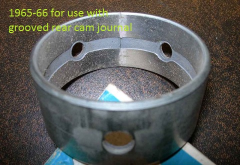
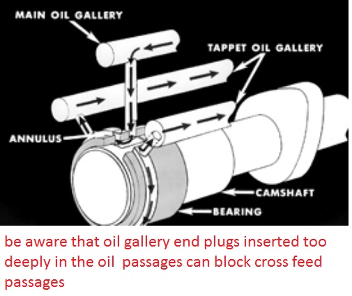
’65-’66 Big-Block Lifter Gallery Oiling: In order to feed pressurized oil to the galleries that feed the lifters, the ’65-’66 big-blocks used a combination of a groove in the rear cam journal and a rear cam bearing with a matching groove on its inside diameter. Oil entered the bearing through a hole at the bottom, traveled around the journal through the groove in the bearing and the journal, and exited the bearing through two holes at the top that aligned with two holes in the block; those two holes fed the oil galleries on each side that fed the lifters. Both the cam journal and the cam bearing MUST have the groove in order to provide adequate oil flow to the lifters, and the bearing must have the two exit holes at the top.

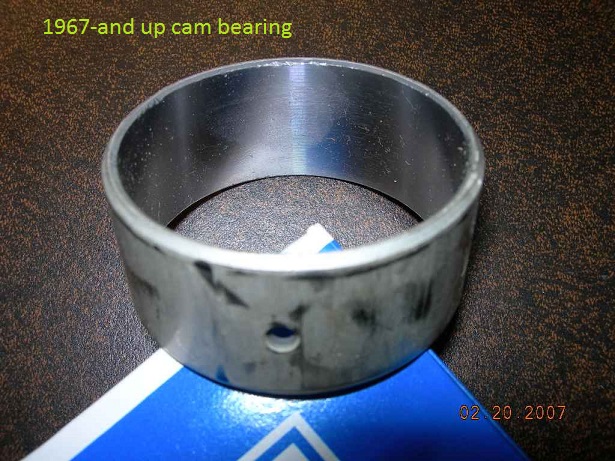
’67-Up Big-Block Lifter Gallery Oiling: Starting in 1967, Chevrolet redesigned the oiling path to the lifter galleries. The groove was removed from both the rear cam journal AND from the I.D. of the rear cam bearing, and an annular groove was machined into the rear cam bearing bore in the block instead. With the smooth rear journal and cam bearing surfaces, oil entered the bearing through the same hole in the bottom, but part of it flowed around the outside diameter of the cam bearing, through the groove machined in the bearing bore, and exited through the same two holes in the block at the top that fed the lifter galleries. The cam bearing now had only one hole, at the bottom.

What This Means To You: Your block dictates what you can use. The 1967 non-grooved cam and non-grooved one-hole rear bearing will NOT work in a ’65-’66 block, period; you need the cam with the grooved rear journal and the rear cam bearing with the three holes and the groove on its I.D. The cam isn’t a big problem – any competent machine shop can cut the required groove in the rear journal of the camshaft, and all you need then is the correct rear cam bearing, which will be included with a ’65-’66-only big-block cam bearing set.

Photo below is the '67-up rear cam bearing, with only one (inlet) hole at the bottom and no groove; the rest of the oil goes around the OUTSIDE of the bearing shell (through the annular groove machined in the bearing bore in the block), to feed the two lifter gallery holes at the top of the bearing bore. '65-'66 3-hole grooved bearing also shown for comparison.
65_66.jpg

on the early big blocks oil from the oil pump enters the rear cam bearing at 6 0,clock travels around both sides of the rear cam journal and exits into both lifter oil feed gallery passages at about 10 o,clock and 2 o,clock to feed the lifters
67-up.jpg

on the later big blocks oil from the oil pump enters the rear cam bearing at about 2 0,clock travels around both sides of the rear cam journal and exits slowly thru bearing clearances but the vast majority of the oil flow from the pump travels around the outside of the bearing thru the groove in the block the routes oil directly to the lifter gallerys on both banks into both lifter oil feed gallery passages at about 10 o,clock and 2 o,clock to feed the lifters
USE YOUR PLASTIGAUGE AND PRECISSION MEASSURING TOOLS , MEASSURE CLEARANCES AND BE SURE YOUR NOT BINDING< ANYPLACE

oilcappass2.jpg

notice the open slot between the rear main cap supporting the oil pump and bearing shell support and the area supporting the rear main seal, this prevents PRESSURIZED oil from the bearings reaching the rear main seal.
oilcappass3.jpg

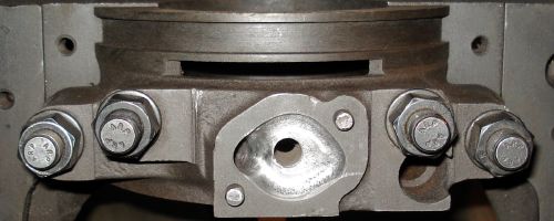
the as cast recess in the rear main cap where the oil pump mounts can be rather restrictive and shallow, and if your replacing a missing main cap , with one from a different block you'll very likely be required to have the block?cap too be line honed to get the correct alignment and fit clearances for the crank shaft
oilcappass4.jpg


mainoilcap1.jpg

mainoilcap2.jpg


mainoilcap3.jpg


cambutclear.jpg

c60462.jpg

0106em_bbshootout_14_z.jpg

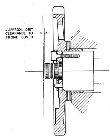
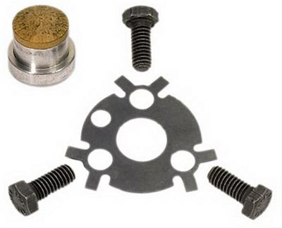
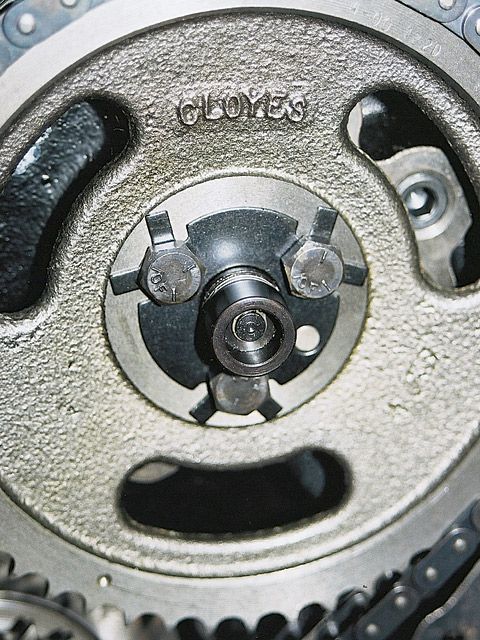
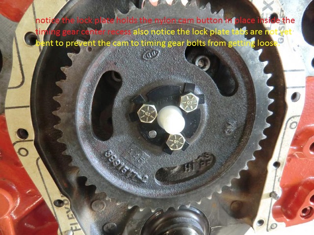
this cam buttons correctly installed but the retainer plate tabs have not been bent up to lock the bolt heads from rotating
plastig1.JPG

71DiMRV8kgL._SX522_.jpg


plastig2.png

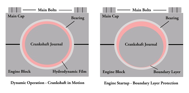
keep in mind the assembly lube or even oil on the bearing surfaces has a surface shear limit,
that why the crank is harder to start rotating but the required effort to keep it spinning is significantly lower,
your initial effort to twist the crank must break that surface tension on the lube,
once its sheared the lube forms a lubricating layer and metal to metal contact is prevented as the lube forms a barrier layer

bearingwedgea.jpg

bearingwedge.png

bearingwedgeb.png

plastig4.jpg

plastig5.jpg

plastig6.jpg

plastig7.jpg

plastig8.jpg

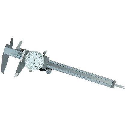
always accurately measure the crank main journals, and remember the crank and block bearing sizes on a 400 sbc and 350 smc are different as are the early 283-327 sbc
spacerbearing5a.jpg

calipersaa.jpg


heres some info from napa
http://knowhow.napaonline.com/know-notes-measure-engine-bearing-clearance/
bearing_clearance_feature.jpg

KNOW-HOW NOTES: HOW TO MEASURE ENGINE BEARING CLEARANCE


When rebuilding an engine, there is nothing more critical than getting the bearing clearance correct. Every engine has its own bearing clearance specs, but the measuring procedure does not change. There are two main methods used for checking bearing clearance – Plastigage® or gauges.

Plastigage®
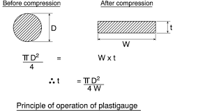
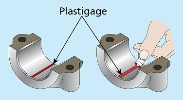
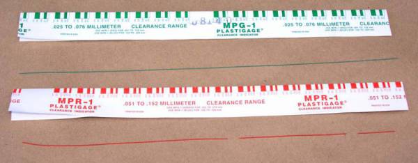
Plastigage® has its place, as it serves a purpose for backing up and verifying your bearing clearances. Plastigage® is a special plastic that expands a specific amount when squeezed. Sold in sleeves of threads for specific thickness ranges, Plastigage® works really well in situations where the components are not being completely removed, such as in-engine bearing replacement, and other non-automotive uses. Originally put on sale in 1948, Plastigage® is fairly accurate and the method of choice for many DIY enthusiasts.

IMG_7335a.jpg

Plastigage® is quite useful, so don’t automatically throw it out. It is a good way of verifying your measurements.

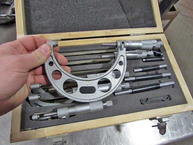
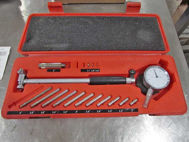
In reality, the right way to check bearing clearances is with the proper tools. In order to check the clearances for rod and main bearings, you need a set of micrometers and a dial-bore gauge. These are readily available at budget prices, but if you are going to use them a lot, better quality tools are advised.

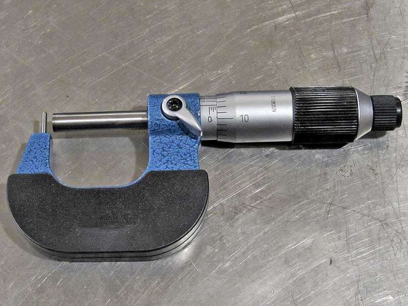
Micrometer
This looks like a horseshoe with a round handle attached to one leg. Micrometers typically only adjust 1”, so you need multiple sizes to get the job done. A 1-6” set usually has the sizes you need for most jobs.

IMG_6558a.jpg

This a complete micrometer set that will cover just about anything you could need for automotive work.

Dial-Bore Gauge
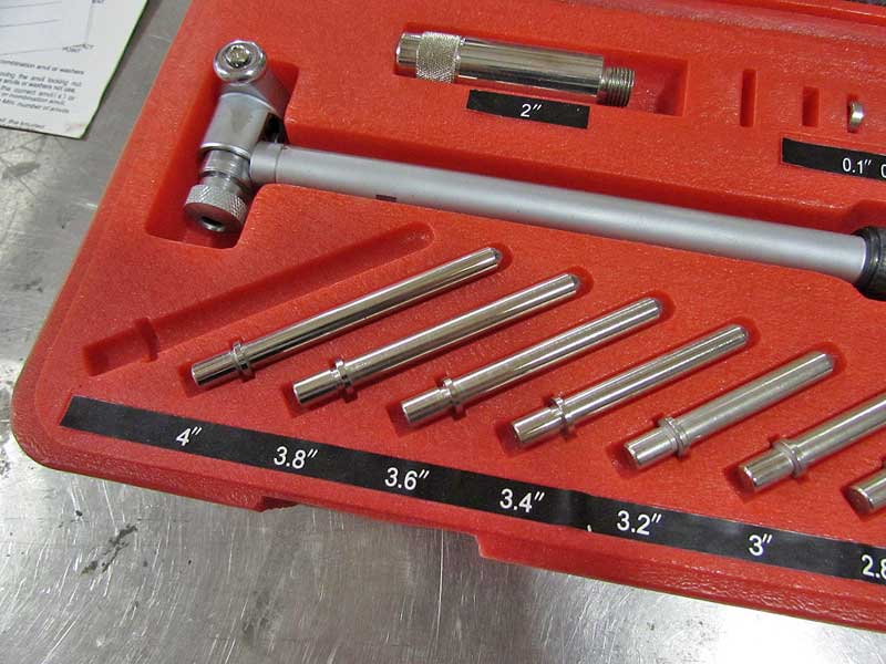
This tool uses a dial indicator on a post with a small wheeled measuring apparatus. These are adjustable through graduated post extenders that increase the diameter of the measurement circle.

IMG_6564a.jpg

The dial bore gauge measures the inside of round holes, such as the bearing journals.


IMG_6565a.jpg

This one tool can measure 2″ up to 6″ diameter holes.

Both tools are needed in order to check the interior and exterior dimensions of the crankshaft, rods and engine block journals, as well as the thickness of the bearings themselves. Making all of this happen can be tricky, so here are a few tips to help you work through the process.

Using a micrometer means following a couple of rules. The key to a micrometer is not to tighten it too much. There are two knobs – a large knob and then a smaller one. The smaller knob clicks when the micrometer is in contract with the part. DO NOT use the larger knob to tighten the mic onto the part as this can damage the tool.

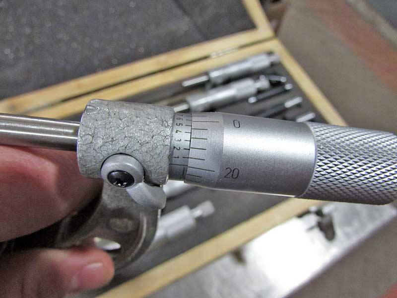
Reading a micrometer can be confusing, they are graduated differently than rulers. The inside barrel is marked in .100” (large) and .025” (small) notations. Once you reach those marks, the scale on the thimble (large rotating knob) comes into play to get the finite measurements. The thimble is scaled in .001 divisions from .000 up to .025”.

IMG_6562a.jpg

The hash marks are how you read micrometers. It takes some practice, and unless you use them daily, you will forget over time. Just be patient.

Outer Diameter Measurements
These are fairly simple, just choose the micrometer that covers the range needed and measure. It is a good idea to check the part in three different locations, staying away from the oiling holes as they can throw off the measurements due to the chamfers.

Measuring Bearings
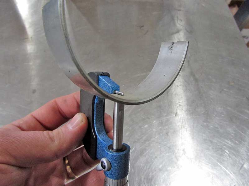
Even though bearings are flat enough, they cannot be accurately measured with calipers, instead you need a micrometer. There are special micrometers available for measuring round inside surfaces, but you don’t have to have one of those. Instead, you can use the shaft of a drill bit (good quality, and use the smooth part, not the fluted section). Place the drill bit on the inside curve, and then measure the bearing. Subtract the thickness of the drill bit (measure, don’t assume), and you will have the thickness of the bearing.

IMG_6571a.jpg

An tube mic is useful for measuring bearings and over inside-curved pieces. In a pinch, you can use a drill bit or pushrod and an outside mic.


IMG_6576a.jpg

This is how bearings are measured. DO NOT use calipers, you can easily scratch the babbit material and ruin the bearing, plus they are just not accurate enough.

Using A Dial-Bore Gauge
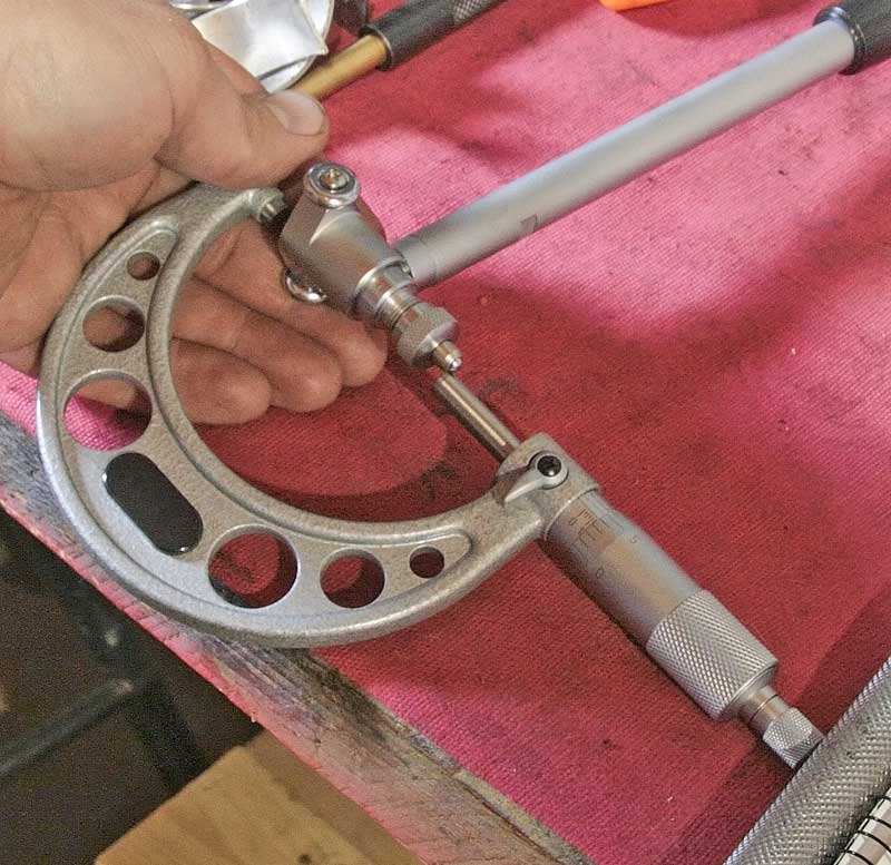
Setting up a dial-bore gauge requires using a micrometer. You need the base measurement of the bore, rough is enough. Set the gauge to just over the diameter, using the correct extensions. Set the micrometer to the bore size you need, then place the gauge between inside the mic and rock the gauge back and forth, and side to side. Note the minimum reading, and zero the gauge to that reading.

crop-1a.jpg

Setting the dial bore gauge uses both the bore gauge and a micrometer. Make sure the measuring ends are square inside the micrometer’s anvils (not as shown)

Inside Diameter Measurements
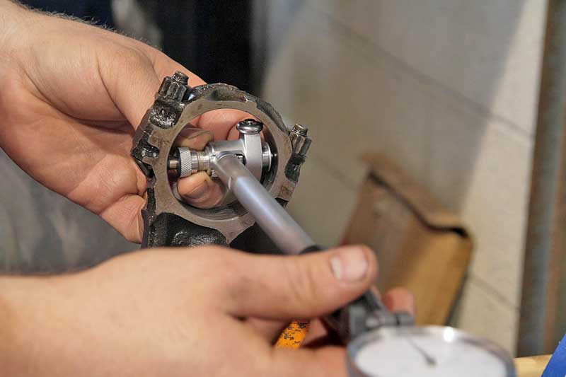
With the dial-bore gauge set to the correct size, place the gauge inside the journal or rod end and rock the gauge back and forth and side to side, just like the setup process. Note the smallest diameter, that is the size of the journal. Just like the outside measurements, take the reading in three different places. One note – the bore must be as it would be in use, so torque the caps to their correct specs and they need to be clean, no oil at all.

IMG_5607a.jpg

Place the gauge inside the journal and move it slowly till you find the largest measurement. Take readings in three places.
 
Last edited:
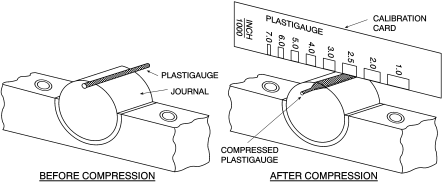
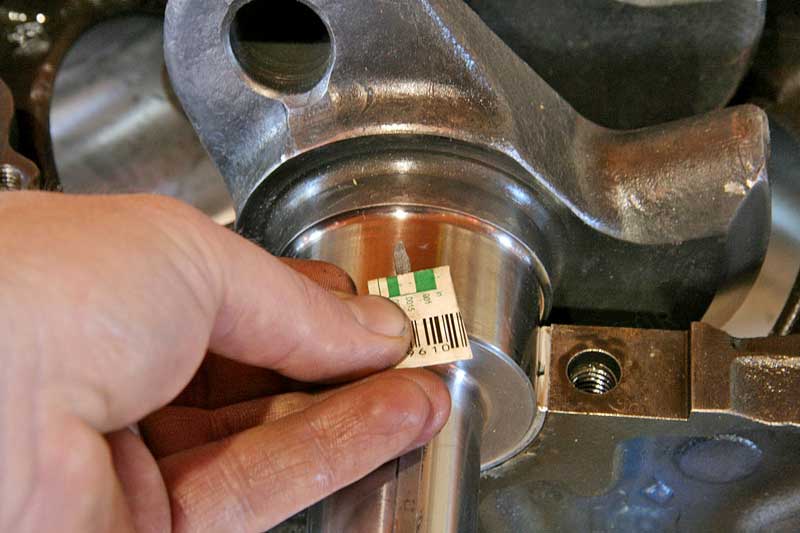
any time you assemble an engine (espoecially with a used crank assembly) youll need to meassure the bearing clearance , accurately and in most cases verify the clearance with plasti-guage.
keep in mind the clearances can, and in most cases will vary between individual journals so you might need to select and instal main or rod bearings that are slightly different to maintain the ideal bearing clearances if some jourmals were in need of an extensive jornal polishing, which by definition is likely to remove at least some of the journals surface as the higher surfaces are reduced to match the lower surface's

yeah Im well aware most newer engine assemblers , just don't understand why most machine work is required, well the block casting , will over time once its repeatedly heated and cooled , deform, and REQUIRE careful machine work to bring the clearances and part alignments back into speck, and yeah even a couple thousands MATTERS to engine durability/longevity
that's why most engine builders vastly prefer the thicker aftermarket block castings (DART/WORLD/BRODIX) as thicker castings tend to move less, in heat cycles) and vastly prefer starting with a block thats been driven for a few thousand miles or a year or so before they build a serious engine, as the casting settles down and stabilizes over several months use.
and repeated heating and cooling cycles

Grumpy said:
Ive found that .0024 - .0028 on the first four main bearings, and .0026-.0031 on the rear main bearing
Ok, what gives here. You called me out when I wanted a dial bore gauge that
measured in .0001. Wish I could remember the exact topic, but it's been too
long now....about 2-3 months ago.

Looks like to me you must be measuring to the 1/10,000 of an inch to quote
numbers like .0024 to .0028 inch.

I'm not mad, just wanting to get a proper explanation and have a discussion
surrounding measuring clearances. hehehehe!!!!

I suppose thats a Great question!
the fact is setting the engine bearing clearances and selecting the type of bearing surface, is a judgement call based on both intended use and the oil viscosity you intend to use.
the higher the average rpm range the greater the oil flow rate over the bearing surfaces and the greater the need for cooling the oil,the difference between what will function fairly well and what would be ideal may not be a great deal different, but in the long term, you should try to get things as close to ideal as you can, every choice made is a compromise in several areas, some choices are of course a bit more critical to the engine function that others and some cam be compensated for to some degree with other parts selected.
example. slightly larger bearing clearances will require a bit larger oil flow rate so a high volume oil pump might not be a bad idea, but that would logically usually require a larger capacity oil pump to provide that flow increase,a baffled oil pan and windage screen to control the oil flow return.
BTW youll find through experience that many of the main bearing sets tend to have the rear main bearing is designed with a slightly larger clearance for some reason

look at the charts below and youll see how the clearance effects oil flow rates ,heat build-up and load capacity, it should become obvious that clearance in the .002-,003 range provide a near ideal compromise in characteristics and a slight change has very little effect , but larger bearing clearances increase flow (with in that .002-.003 range), thus cooling as greater flow absorbs and transfers heat out of the bearing surface slightly more effectively. while tighter clearances slightly increase load capacity but require a thinner viscosity oil being used.
plastig1.JPG

https://www.carshopinc.com/product_info.php/products_id/49347/SPG1-12

71DiMRV8kgL._SX522_.jpg


plastig2.png

yes I use both micrometers and snap gauges and cross check with plasti-gauge
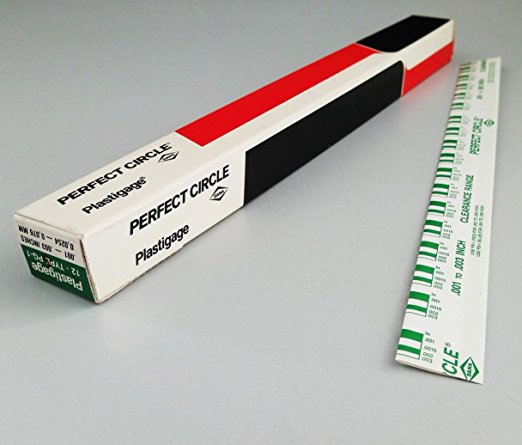
and yes when you compare the crushed width of the plasti-gauge youll find it rarely falls as an exact match to the bar chart tape that is packaged with it so you can judge clearance based on crush width
http://garage.grumpysperformance.com/index.php?threads/bearing-clearances.2726/
plas1v.jpg

plas2v.jpg

yes controling heat is a very significant issue but,
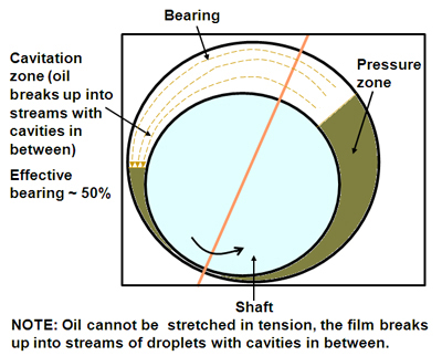
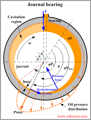
maintaining a pressurized hydraulic film of lubricating oil between the moving surfaces is critical, for durability.
honestly the engines lube system is critical to long term durability, and you really can,t reasonably expect an engine to last if you don,t maintain consistent cooling and lubrication.

122655.jpg


SBCOilingnew.png


p33039_image_large.jpg


p33038_image_large.jpg

p33037_image_large.jpg


bearingh1.jpg

bearingh2a.jpg

bearingh3.jpg

bearingh4.jpg

bearingh5.jpg

bearingh6.jpg

bearingh7.jpg

bearingh8.jpg


bearingh10.jpg

bearingh12.jpg

bearingh13.jpg

bearingh9.jpg

bearingh11.jpg

bearinggroove1.jpg

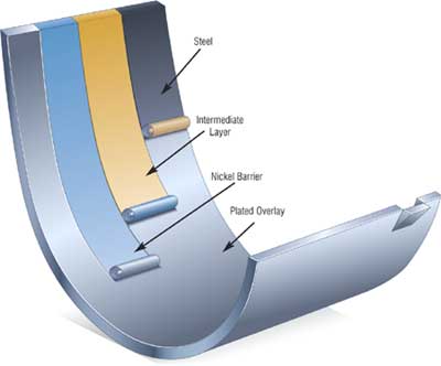
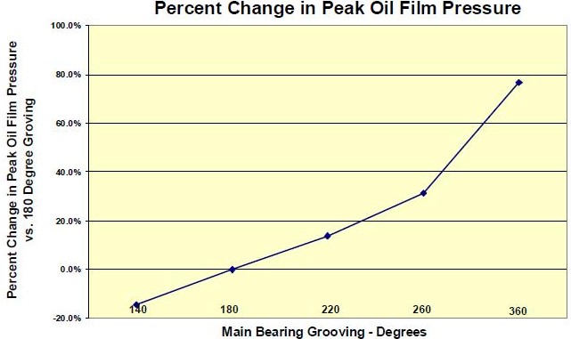
the oil groove terminates before it gets to the bearing parting line. This style of main bearing has accounted for a 15 percent or more increase in hot idle oil pressure. So if you're looking to eliminate some of those unexplained low oil pressure gremlins contact your bearing manufacturer and ask about this style bearing and availability for the engine applications that you are building.

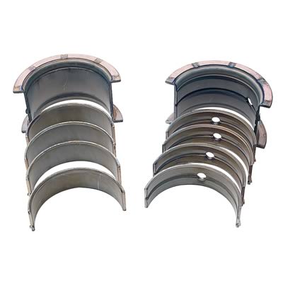
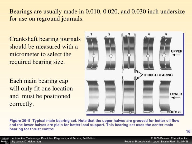
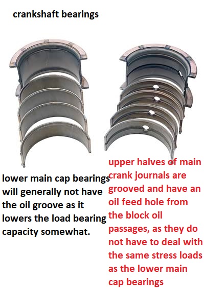
keep in mind only the upper main bearing shell should have an oil groove, having a 360 degree oil groove lowers the bearing ability to handle high rpm loads

MB5160HP%204%20clipped.JPG

THESE BEARING PICTURED ABOVE, LOOK GREAT BUT HAVE LOWER LOAD CAPACITY
cle-ms909h_w.jpg

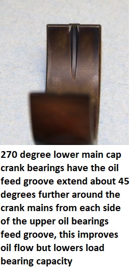
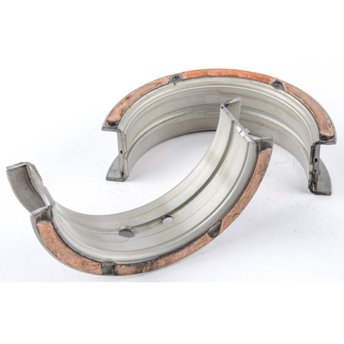
a 180 degree bearing has only the upper in the block grooved to improve oil flow,a 270 degree has the oil feed groove extend further 45 degrees on each lower bearing shell

30-16-728.jpg


270degm.jpg


cle-ms909h.jpg

groove1.jpg


MAIN BEARINGS WITH 360 degree oil grooves
695-ms970al_2.jpg


CHECKING TRUST BEARING CLEARANCE
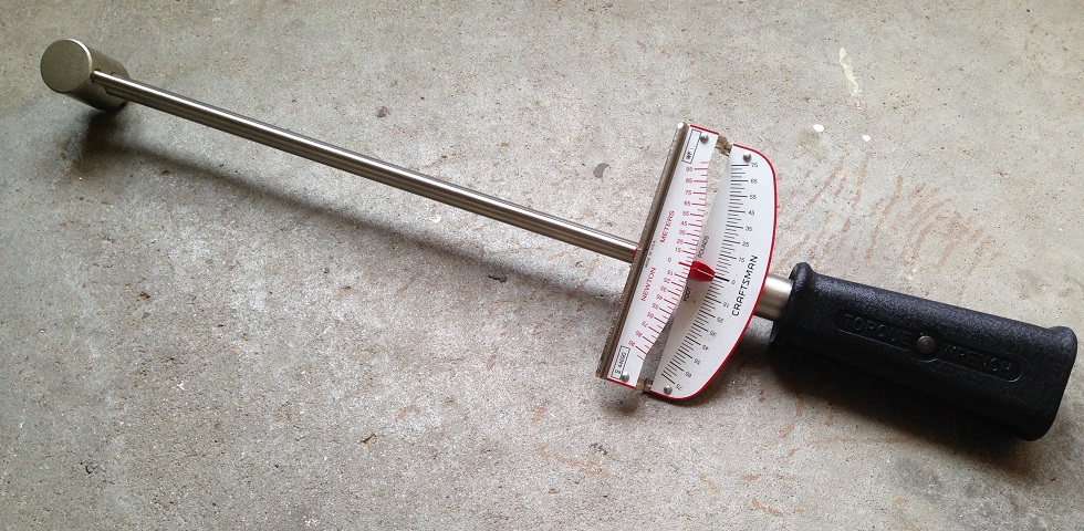
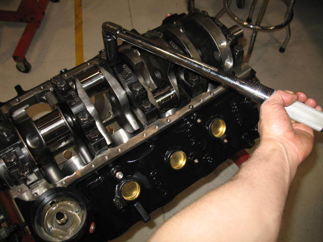
THIS BEAM STYLE TORQUE WRENCH IS THE TYPE TORQUE WRENCH YOU WANT TO CHECK ROTATIONAL RESISTANCE
beam_torque_wrench.jpg


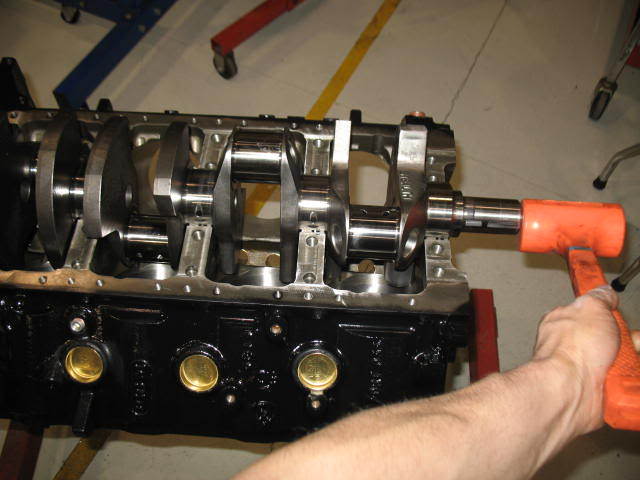
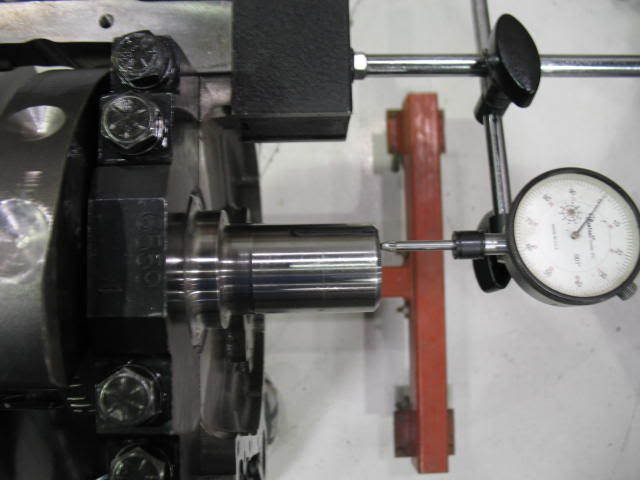
ID SUGGEST YOU KNOCK THE CRANK FRONT TO BACK IN BOTH DIRECTIONS WITH A PLASTIC DEAD BLOW HAMMER SEVERAL TIMES TOO SEAT THE THRUST BEARING BEFORE MEASURING CLEARANCE WITH A DIAL INDICATOR ON THE CRANK SNOUT! (IDEALLY .007-.010)
you can increase thrust bearing clearance, a couple thousands if required, by polishing the thrust bearing to crank surface on a sheet of wet, fine grit, sand paper ,on a sheet of glass, with 1000 grit wet/dry sand paper in a figure 8 pattern obviously clean the bearing carefully befor re-installing it!

thr1.jpg

ALWAYS PAY ATTENTION TO THE PICTURES AND LINKS AND SUB LINKS
NOTICE NO CONNECTING RODS ON THE CRANK WHILE VERIFYING THRUST BEARING CLEARANCES

http://www.harborfreight.com/4-lb-neon-orange-dead-blow-hammer-69004.html
every engine builder needs a plastic dead blow hammer, After torquing the main caps in place and before installing connecting rods you'll need to drive the crank back and forward in the main bearing saddles a few times fore and aft, to properly seat the thrust bearing before taking clearance measurements, and only then proceed to the rod & piston install, rotational resistance checks and checking rod side clearance during assembly.
tru2.jpg


tru3.jpg


tru4.jpg


yes controlling engine and lubrication oil heat is a very significant issue but,
maintaining a pressurized hydraulic film of lubricating oil between the moving surfaces is critical, for durability.your valve springs won,t last 20 minutes without some cooling oil flow to prevent them from over heating and I can,t believe how many people actually believe a crank shaft journal actually rides directly on the bearing surface , without that pressurized film of oil separating the two moving surfaces the bearings are going to be trashed in minutes

http://www.4secondsflat.com/Thrust_bearing_failures.html

Crankshaft Thrust Bearing Failure - Causes & Remedies

For years both transmission and engine rebuilders have struggled at times to determine the cause of crankshaft thrust bearing failures. In most instances, all of the facts concerning the situation are not revealed at the onset of the failure. This has led to each party blaming the other for the failure based only on hearsay or what some "expert" has termed the "cause". Some of those explanations have led to an argument, that ends up in litigation while the truth lingers uncovered in the background. This document is a group effort of combined information compiled by the Automotive Transmission Rebuilders Association (ATRA), the Automotive Engine Rebuilders Association (AERA), the Production Engine Rebuliders Association (PERA), the Automotive Service Association (ASA) and bearing manufacturers. This group of industry experts has assembled the following information to consider and offers solutions that may prevent a similar thrust bearing failure.

Background:
Although thrust bearings run on a thin film of oil, just like radial journal (connecting rod and main) bearings, they cannot support nearly as much load. While radial bearings can carry loads measured in thousandsof pounds per square inch of projected bearing area, thrust bearings can only support loads of a few hundred pounds per square inch. Radial journal bearings develop their higher load capacity from the way the curved surfaces of the bearing and journal meet to form a wedge. Shaft rotation pulls oil into this wedge shaped area of the clearance space to create an oil film which actually supports the shaft. Thrust bearings typically consist of two flat mating surfaces with no natural wedge shape in the clearance space to promote the formation of an oil film to supportthe load.

Conventional thrust bearings are made by incorporating flanges, at the ends of a radial journal bearing. This provides ease in assembly and has been used successfully for many years. Either teardrop or through grooves on the flange, face andwedge shaped ramps at each parting line allow oil to enter between the shaft and bearing surfaces. However, the surface of the shaft, as well as the vast majority of bearing surfaces, are flat. This flatness makes it more difficult to create and maintain an oil film. As an example; if two gauge blocks have a thin film of oil on them, and are pressed together with a twisting action, the blocks will stick together. This is similar to what happens when a thrust load is applied to the end of a crankshaft and oil squeezes out from between the shaft and bearing surfaces. If that load is excessive, the oil film collapses and the surfaces want to stick together resulting in a wiping action and bearing failure. For this reason, many heavy-duty diesel engines use separate thrust washers with a contoured face to enable them to support higher thrust loads. These thrust washers either have multiple tapered ramps and relatively small flat pads, or they have curved surfaces that follow a sine-wave contour around their circumference.
Recent developments:

In the past few years some new automotive engine designs include the use of contoured thrust bearings to enable them to carry higher thrust loads imposed by some of the newer automatic transmissions. Because it’s not practical to incorporate contoured faces on one piece flanged thrust bearings, these new engine designs use either separate thrust washers or a flanged bearing whichis a three piece assembly.

Cause of failure:

Aside from the obvious causes, such as dirt contamination and misassembly, there are only three common factors which generally cause thrust bearing failures. They are:


      • Poor crankshaft surface finish
      • Misalignment
      • Overloading
Surface finish:

Crankshaft thrust faces are difficult to grind because they are done using the side of the grinding wheel. Grinding marks left on the crankshaft face produce a visual swirl or sunburst pattern with scratches - sometimes crisscrossing - one another in a cross-hatch pattern similar to hone marks on a cylinder wall. If these grinding marks are not completely removed by polishing, they will remove the oil film from the surface of the thrust bearing much like multiple windshield wiper blades. A properly finished crankshaft thrust face should only have very fine polishing marks that go around the thrust surface in a circumferential pattern.
Alignment:

The grinding wheel side face must be dressed periodically to provide a clean, sharp cutting surface. A grinding wheel that does not cut cleanly may create hot spots on the work piece leading to a wavy, out-of-flat surface. The side of the wheel must also be dressed at exactly 90° to its outside diameter, to produce a thrust face that is square to the axis of the main bearing journal. The crankshaft grinding wheel must be fed into the thrust face very slowly and also allowed to "spark out" completely. The machinist should be very careful to only remove minimal stock for a "clean-up" of the crankshaft surface.

In most instances a remanufactured crankshaft does not require grinding of the thrust face(s), so the grinding wheel will not even contact them. Oversize thrust bearings do exist. Some main bearing sets are supplied only with an additional thickness thrust bearing. In most of those instances, additional stock removal from the crankshaft thrust face surface may be required. Crankshaft end float should be calculated and determined before grinding additional material from the thrust face.

Crankshaft grinding wheels are not specifically designed for use of the wheel side for metal removal. Grinding crankshaft thrust faces requires detailed attention during the procedure and repeated wheel dressings may be required. Maintaining sufficient coolant between the grinding wheel and thrust surface must be attained to prevent stone loading and "burn" spots on the thrust surface. All thrust surface grinding should end in a complete "spark out" before the grinding wheel is moved away from the area being ground. Following the above procedures with care should also maintain a thrust surface that is 90° to the crankshaft centerline.

When assembling thrust bearings:


      • Tighten main cap bolts to approximately 10 to 15 ft.lb. to seat bearings, then loosen.
      • Tap main cap toward rear of engine with a soft faced hammer.
      • Tighten main cap bolts, finger tight.
      • Using a bar, force the crankshaft as far forward in the block as possible to align the bearing rear thrust faces.
      • While holding shaft in forward position, tighten main cap bolts to 10 to 15 ft.lbs.
      • Complete tightening main cap bolts to specifications in 2 or 3 equal steps.
The above procedure should align the bearing thrust faces with the crankshaft to maximize the amount of bearing area in contact for load carrying.

Loading:

A number of factors may contribute to wear and overloading of a thrust bearing, such as:

1. Poor crankshaft surface finish.

2. Poor crankshaft surface geometry.

3. External overloading due to.

a) Excessive Torque converter pressure.

b) Improper throw out bearing adjustment.

c) Riding the clutch pedal.

d) Excessive rearward crankshaft load pressure due to a malfunctioning front mounted accessory drive.

Note: There are other, commonly-thought issues such as torque converter ballooning, the wrong flexplate bolts, the wrong torque converter, the pump gears being installed backward or the torque converter not installed completely. Although all of these problems will cause undo force on the crankshaft thrust surface, it will also cause the same undo force on the pump gears since all of these problems result in the pump gear pressing on the crankshaft via the torque converter. The result is serious pump damage, in a very short period of time (within minutes or hours).

Diagnosing the problem:

By the time a thrust bearing failure becomes evident, the partshave usually been so severely damaged that there is little if any evidence of the cause. The bearing is generally worn into the steel backing which has severely worn the crankshaft thrust face as well. So how do you tell what happened? Start by looking for the most obvious internal sources.
Engine related problems:


      • Is there evidence of distress anywhere else in the engine that would indicate a lubrication problem or foreign particle contamination?
      • Were the correct bearing shells installed, and were they installed correctly?
      • If the thrust bearing is in an end position, was the adjacent oil seal correctly installed? An incorrectly installed rope seal can cause sufficient heat to disrupt bearing lubrication.
      • Examine the front thrust face on the crankshaft for surface finish and geometry. This may give an indication of the original quality of the failed face.
Once you are satisfied that all potential internal sources have been eliminated, ask about potential external sources of either over loading or misalignment.

Transmission related problems:


      • Did the engine have a prior thrust bearing failure?
      • What external parts were replaced?
      • Were there any performance modifications made to the transmission?
      • Was an additional cooler for the transmission installed?
      • Was the correct flexplate used? At installation there should be a minimum of 1/16" (1/8" preferred, 3/16" maximum) clearance between the flex plate and converter to allow for converter expansion.
      • Was the transmission property aligned to the engine?
      • Were all dowel pins in place?
      • Was the transmission-to-cooler pressure checked and found to be excessive? If the return line has very low pressure compared to the transmission-to-cooler pressure line, check for a restricted cooler or cooler lines.
      • If a manual transmission was installed, was the throw out bearing properly adjusted?
      • What condition was the throw out bearing in? A properly adjusted throw out bearing that is worn or overheated may indicate the operator was "Riding The Clutch".
How does the torque converter exert force on the crankshaft?

There are many theories on this subject, ranging from converter ballooning to spline lock. Most of these theories have little real bases and rely little on fact. The force on the crankshaft from the torque converter is simple. It is the same principle as a servo piston or any other hydraulic component: Pressure, multiplied by area, equals force. The pressure part is easy; it’s simply the internal torque converter pressure. The area is a little trickier. The area that is part of this equation is the difference between the area of the front half of the converter and the rear half. The oil pressure does exert a force that tries to expand the converter like a balloon (which is why converter ballooning is probably often blamed), however, it is the fact that the front of the converter has more surface area than the rear (the converter neck is open) that causes the forward force on the crankshaft. This difference in area is equal to the area consumed by the inside of the converter neck. The most common scenario is the THM 400 used behind a big-block Chevy. General Motors claims that this engine is designed to sustain a force of 210 pounds on the crank shaft. The inside diameter of the converter hub can vary from 1.5 inches up to 1.64 inches. The area of the inside of the hub can then vary from 1.77 square inches to 2.11 inches. 210 pound of force, divided by these two figures offers an internal torque converter pressure of 119 psi to 100 psi, respectively. That is to say, that depending on the inside diameter of the hub, it takes between 100 to 119 psi of internal converter pressure to achieve a forward thrust of 210 pounds. The best place to measure this pressure is the out-going cooler line at the transmission because it is the closest point to the internal converter pressure available. The pressure gauge must be "teed" in so as to allow the cooler circuit to flow. Normal cooler line pressure will range from 50 psi to 80 psi , under a load in drive.
Causes for excessive torque converter pressure:

There are two main causes for excessive torque converter pressure: restrictions in the cooler circuit and modifications or malfunctions that result in high line pressure. One step for combating restrictions in the cooler circuit is to run larger cooler lines. Another, is to install any additional cooler in parallel as opposed to in series. This will increase cooler flow considerably. An additional benefit to running the cooler in parallel is that it reduces the risk of over cooling the oil in the winter time—especially in areas where it snows. The in-parallel cooler may freeze up under very cold conditions, however, the cooler tank in the radiator will still flow freely. Modifications that can result in higher than normal converter pressure include using an overly-heavy pressure regulator spring, or excessive cross-drilling into the cooler charge circuit. Control problems such as a missing vacuum line or stuck modulator valve can also cause high pressure.

What will help thrust bearings survive? When a problem application is encountered, every effort should be made to find the cause of distress and correctit before completing repairs, or you risk a repeat failure.

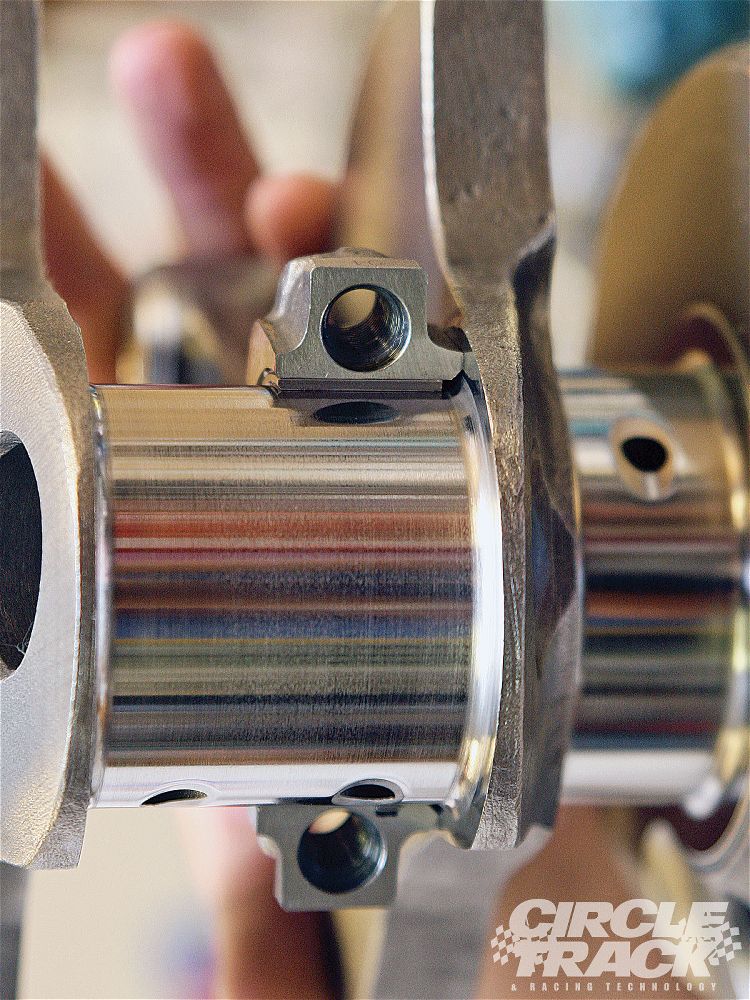
A simple modification to the upper thrust bearing may be beneficial in some engines. Install the upper thrust bearing in the block to determine which thrust face is toward the rear of the engine. Using a small, fine tooth, flat file, increase the amount of chamfer to approximately .040" (1 mm) on the inside diameter edge of the bearing parting line. Carefully file at the centrally located oil groove and stroke the file at an angle toward the rear thrust face only, as shown in the illustration below. It is very important not to contact the bearing surface with the end of the file. The resulting enlarged ID chamfer will allow pressurized engine oil from the pre-existing groove to reach the loaded thrust face. This additional source of oiling will reach the loaded thrust face without passing through the bearing clearance first (direct oiling). Since there may be a load against the rear thrust face, oil flow should be restricted by that load and there should not be a noticeable loss of oil pressure. This modification is not a guaranteed "cure-all". However, the modification should help if all other conditions, such as surface finish, alignment, cleanliness and loading are within required limits.


bearing1.jpg


Other External Problems. Aside from the items already mentioned, there is another external problem that should be considered. Inadequate electrical grounds have been known to exacerbate thrust surface wear. Excessive current in the vehicle drive train can damage the thrust surface. It affects the thrust bearing as though the thrust surface on the crankshaft is not finished properly finished (too rough). Excessive voltage in the drive train can be checked very easily. With the negative lead of a DVOM connected to the negative post of the vehicle battery and the positive lead on the transmission, there should be no more than .01 volts registering on the meter while the starter is turning over the engine. For an accurate test, the starter must operate for a minimum of four seconds without the engine starting. It is suggested to disable the ignition system before attempting this test. If the voltage reading observed is found to be excessive, add and/or replace negative ground straps from the engine to the vehicle frame and transmission to frame until the observed voltage is .01 volts or less. Note: Some systems may show a reading of .03volts momentarily but yet not exhibit a problem. For added assurance, it is a good idea to enhance the drive train grounding with larger battery cables or additional ground straps.

A special thank you goes out to Dennis Madden of ATRA, Dave Hagen of AERA, Ed Anderson of ASA, Roy Berndt of PERA and John Havel of AE Clevite for their contributions to this article.

The AERA Technical Committee

March 1998 - TB 1465R


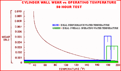
when you say 215F do you mean the normal rise in temp after shut-down?
no!
oil temps SHOULD reach 215F occasionally during engine operation,
to insure all moisture is boiled off
but keep in mind , oil in the sump is going to be significantly cooler than,
oil flowing over,
rocker pivot balls,
cam lobes,
bearings,
valve springs lifters,
piston skirts and rings
ETC.
oil, flowing over the moving and sliding components absorbs a great deal of heat,
that hot oil flowing over the engine block and heads has,
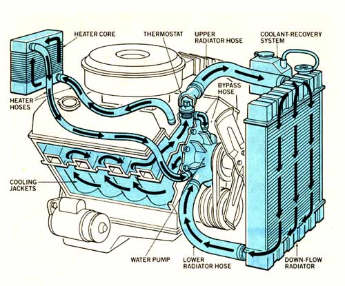
its heat load rapidly absorbed and transferred too coolant,
flowing through the major components, that coolant absorbs heat from the hot oil,
and transfers it to the outside air flow ,
and air flowing over the oil pan and valve covers is easily 40F-100F cooler than the oil,
this is how much of the initial heat is transferred,now oil in your oil pan will be by design cooler than it is in other locations,
and oil flow cycles endlessly so while your engine may only hold 4-8 quarts, theres 2-7 gallons a minute passing through the oil pump,
that flow changes, depending on clearances and rpms of course, so the longer any engine runs the more passes,
the individual oil molecules have of being repeatedly heated and cooled, thus moisture boiled out, but moisture will not be totally removed unless,
oil reaches about 215F repeatedly,

this almost mandates a 190F-205F oil pan oil temp.

img212.gif


ChevyOilingPluga.jpg

sbcoilh3.jpg

coolantflow.jpg


http://garage.grumpysperformance.co...sion-and-oil-cooler-increases-durability.176/

http://garage.grumpysperformance.com/index.php?threads/bearings-and-oil-flow.150/


http://garage.grumpysperformance.co...k-after-a-cam-lobe-rod-or-bearings-fail.2919/

http://garage.grumpysperformance.com/index.php?threads/oil-system-mods-that-help.2187/


http://garage.grumpysperformance.co...gine-project-dart-shp.3814/page-23#post-21571

http://garage.grumpysperformance.com/index.php?threads/basic-info-on-your-v8-lube-system.52/

http://garage.grumpysperformance.com/index.php?threads/bearings-and-oil-flow.150/


http://garage.grumpysperformance.com/index.php?threads/oil-accumulator.1280/

http://garage.grumpysperformance.co...te-filter-require-a-new-pump.3144/#post-62980

http://garage.grumpysperformance.co...l-cooler-increases-durability.176/#post-48374

http://garage.grumpysperformance.co...y-in-building-a-good-engine.11682/#post-54682

http://forum.grumpysperformance.com/viewtopic.php?f=54&t=3536&p=9372#p9372

http://garage.grumpysperformance.co...g-up-oil-feed-holes-in-bearings-shells.10750/

http://garage.grumpysperformance.co...ng-clearances-engine-builders-magazine.11965/

http://garage.grumpysperformance.com/index.php?threads/valve-spring-cooling-via-engine-oil.6491/

http://garage.grumpysperformance.co...oil-passages-and-improved-oil-flow-mods.3834/

http://garage.grumpysperformance.co...m-sure-your-convinced-its-the-oil-pump.11085/

http://garage.grumpysperformance.com/index.php?threads/reducing-friction-and-pumping-losses.8966/

as a general rule you select .001 bearing clearance for every inch of bearing journal diameter,

Rod bearings 0.002 - 0.025" , side clearance 0.010 - 0.020"

Main bearings 0.002 - 0.003" for most engines ( 0.020-0.025 bearing clearance on small blocks, .025-.027 bearing clearance is about ideal, on big blocks ), 0.005 - 0.007 crankshaft end play

http://garage.grumpysperformance.co...ting-resistance-to-look-for.11312/#post-51472

http://garage.grumpysperformance.co...uring-crank-bearing-journals.5478/#post-16429

http://garage.grumpysperformance.co...ng-clearances-engine-builders-magazine.11965/

http://garage.grumpysperformance.com/index.php?threads/can-i-get-it-polished.9214/#post-43456

http://www.competitionproducts.com/Bearings-Bearing-Spacers/departments/179/

http://garage.grumpysperformance.co...shaft-journal-surface-finnish.2728/#post-9886

http://garage.grumpysperformance.com/index.php?threads/bearing-install-tips.3449/

http://garage.grumpysperformance.com/index.php?threads/which-torque-wrench.342/#post-59396

http://garage.grumpysperformance.co...guess-on-clearances-and-journal-surface.9955/

http://garage.grumpysperformance.com/index.php?threads/bearing-install-tips.3449/
 
Last edited:
Back
Top