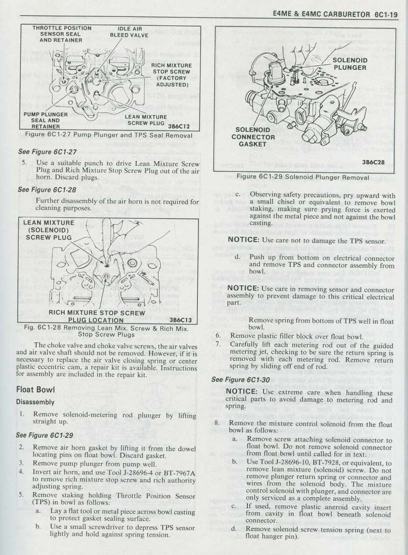
Is there a site where I can look up and decipher what application any particular Q-Jet fits? I have the Corvette listings but I cannot find my Q-jet rebuilding books at this time. Thanks
You are using an out of date browser. It may not display this or other websites correctly.
You should upgrade or use an alternative browser.
You should upgrade or use an alternative browser.
Looking for Q-Jet index
- Thread starter chromebumpers
- Start date
theres several links and sub links in these threads you might find very useful
viewtopic.php?f=55&t=1144&p=8206&hilit=quadrajet#p8206
viewtopic.php?f=55&t=2970&p=7821&hilit=quadrajet#p7821
viewtopic.php?f=44&t=1142&p=2307&hilit=quadrajet#p2307
viewtopic.php?f=44&t=543&p=682&hilit=quadrajet#p682
http://quadrajetparts.com/rochester-qua ... 28_28.html
http://www.lbfun.com/warehouse/tech_inf ... 0Paper.pdf
viewtopic.php?f=44&t=368&p=450&hilit=pontiac+edelbrock#p450
http://www.newagemetal.com/pages/Chevro ... 81_jpg.htm
http://www.newagemetal.com/pages/Chevrolet/75/index.htm
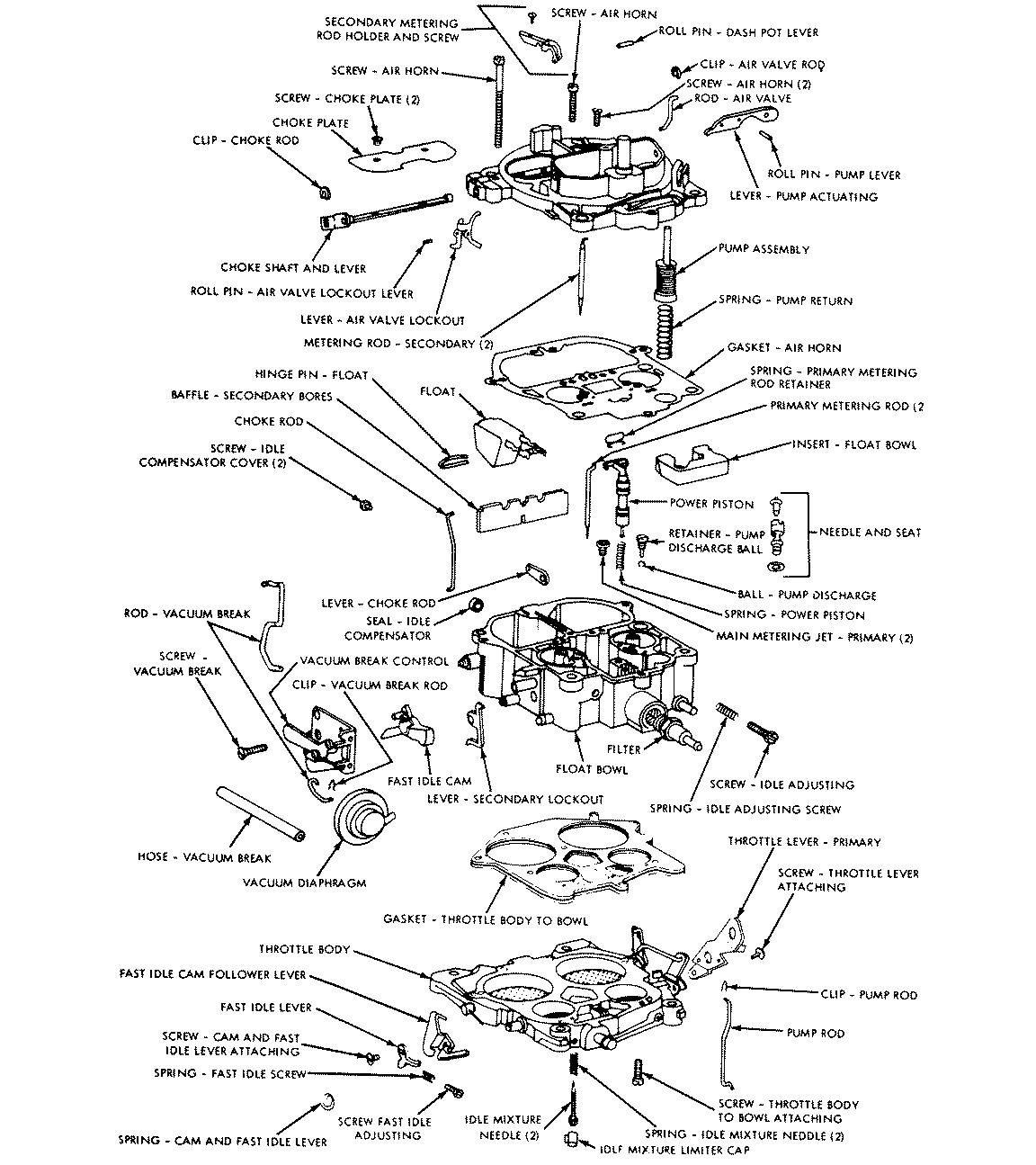

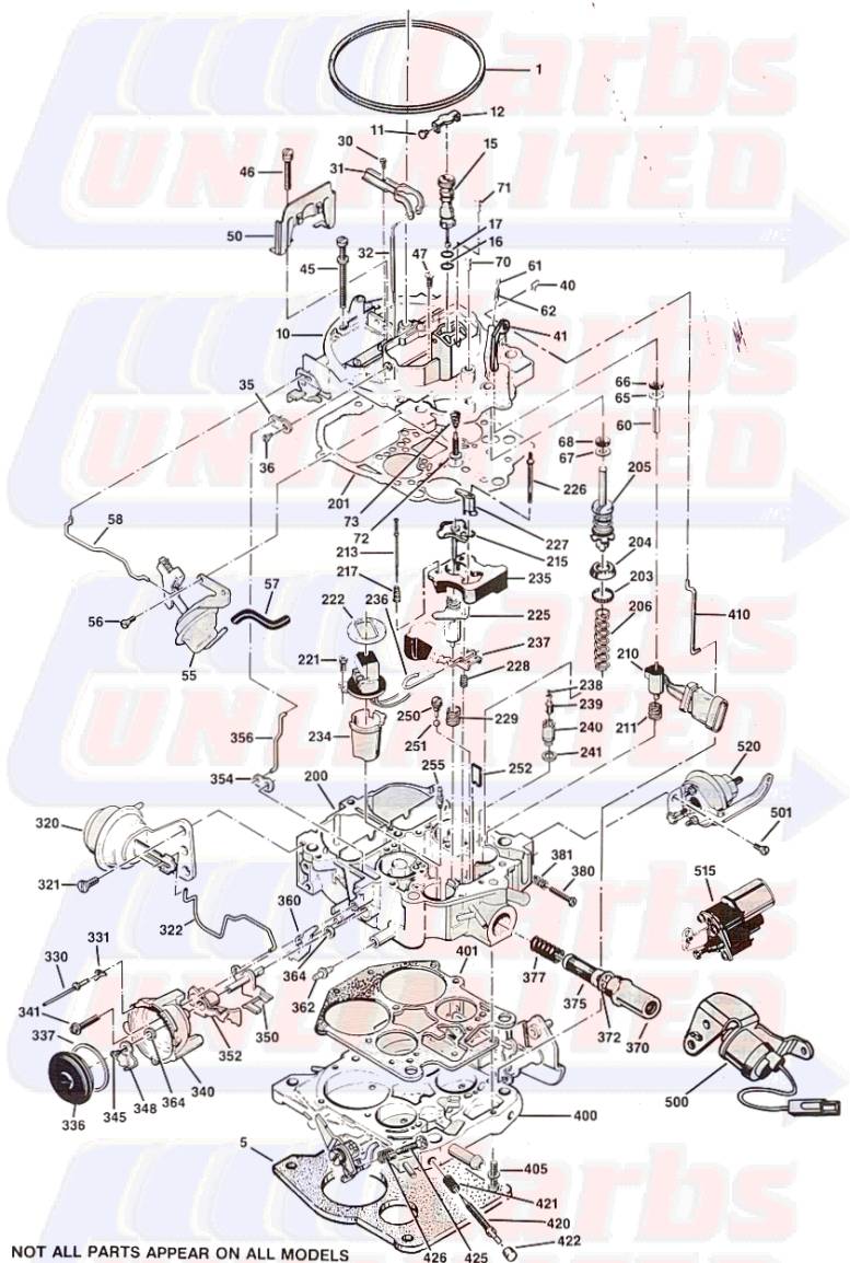
QuadraJet Secondary Metering Rods
Damon Mar 31 2006 - 3:41pm
Degrees of Secondary Air Valve Opening vs.Rod Diameter in Secondary Jet
Rod diameter measured in ten thousandths of an inch.(.0001")
Secondary Jets are all .1360" and non-removable from carburetor
I.D. Code 0 deg. 20 deg. 40 deg. 60 deg. 70 deg. 80 deg. 90 deg. Tip length GM Part #
AD 1346 1280 1084 812 627 397 222 S 7033772
CB 1347 1287 1197 997 897 547 297 S 7042335
BV 1347 1287 1197 1097 897 547 297 S 7040724
DX 1320 1247 1090 600 400 300 300 M 17064719
DC 1347 1236 1129 1024 599 300 300 M 7047816
CC 1347 1236 1129 1024 599 300 300 M 7042356
BY 1287 1217 1062 817 667 317 317 M 7040856
DU 1280 1244 1075 847 547 337 337 M 17059952
DS 1310 1244 1075 847 547 337 337 M 17056618
DF 1339 1262 1075 847 547 337 337 M 7048512
DG 1342 1244 1075 847 547 337 337 M 7048890
CF 1347 1244 1075 847 547 337 337 M 7044775
DM 1334 1281 1155 853 655 482 393 S 17050221
CJ 1339 1244 1075 807 419 419 397 L 7045780
AX 1339 1244 1075 807 419 419 397 L 7033549
BB 1339 1244 1075 807 419 419 397 L 7034335
BW 1317 1247 1087 897 597 397 397 M 7040767
CA 1322 1277 1147 937 797 397 397 M 7042304
BH 1342 1290 1159 932 519 397 397 M 7035916
BM 1342 1290 1159 932 519 397 397 M 7037744
CM 1342 1294 1165 932 519 397 397 M 7045840
BG 1352 1294 1165 932 519 397 397 M 7034822
BF 1325 1315 1192 1021 891 639 397 S 7034400
BK 1325 1315 1193 1021 891 639 397 S 7037295
BJ 1333 1315 1193 1021 891 639 397 S 7036077
CS 1330 1287 1197 1097 897 687 397 S 7045924
BP 1337 1287 1197 1097 997 687 397 S 7038034
CE 1347 1244 1075 847 547 410 410 M 7043771
BN 1329 1288 1147 957 793 503 410 S 7036671
BL 1329 1311 1188 1021 891 691 410 S 7037733
BE 1329 1311 1188 1021 891 691 410 S 7034377
DA 1333 1244 1075 847 577 440 440 M 7046010
CY 1333 1244 1075 847 577 440 440 M 7046004
CV 1332 1291 1154 927 527 527 527 L 7045984
AU 1345 1291 1154 927 527 527 527 L 7033655
CK 1345 1291 1154 927 527 527 527 L 7045781
AH 1345 1291 1154 927 727 527 527 M 7033812
EJ 1355 1350 1200 1047 837 687 540 S 17081930
EA 1339 1262 1172 1000 825 721 547 S 17080091
CR 1339 1262 1172 1097 997 747 547 S 7045923
BU 1347 1262 1172 1097 997 747 547 S 7040725
CP 1320 1247 1090 879 743 578 567 M 7045842
DH 1332 1247 1090 879 743 578 567 M 7048992
ED 1332 1247 1090 879 743 578 567 M 17081878
BA 1332 1247 1090 879 743 578 567 M 7034337
AL 1349 1247 1090 879 743 578 567 M
CD 1351 1264 1107 755 567 567 567 L 7042719
DZ 1325 1290 1150 879 743 578 567 M 17075268
AV 1338 1292 1132 907 757 567 567 M 7033182
AP 1345 1292 1132 907 757 567 567 M 7033981
AJ 1345 1292 1132 907 757 567 567 M 7033628
AZ 1350 1292 1157 957 567 567 567 L 7033889
EG 1350 1292 1157 957 847 697 567 S 17081881
AK 1350 1292 1157 957 847 697 567 S 7033104
CH 1350 1292 1157 957 847 697 567 S 7045779
CX 1346 1294 1165 932 567 567 567 L 7045985
BZ 1352 1294 1165 932 567 567 567 L 7042300
AY 1352 1294 1165 932 567 567 567 L 7033830
EK 1340 1294 1165 932 790 567 567 M 17082409
EF 1340 1294 1165 932 790 617 567 M/S 17081880
CN 1340 1294 1165 932 790 617 567 M/S 7045341
AR 1352 1294 1165 932 790 617 567 M/S 7033171
EE 1323 1250 1093 882 746 581 570 M 17081879
DR 1323 1250 1093 882 746 581 570 M 17053659
DV 1348 1294 1168 935 793 620 570 M/S 17062170
BD 1332 1312 1168 939 805 577 577 M 7034365
BC 1352 1294 1174 1015 901 599 581 M 7034300
DN 1355 1297 1108 1019 904 602 584 M 17053703
BT 1338 1292 1132 907 787 597 597 M 7040601
EC 1350 1292 1157 847 697 610 610 M 17081095
DJ 1337 1262 1172 1097 997 847 747 unique rod-
taper
continues
down to
647 7048908
CL 1350 1294 1176 984 667 667 667 L 7045782
AT 1350 1294 1176 984 667 667 667 L 7033658
DL 1336 1260 1127 939 824 711 679 M/S 7048892
EH 1325 1267 1137 945 829 721 686 M/S 17081882
DP 1325 1267 1137 945 829 721 686 M/S 17053531
DB 1334 1294 1177 1010 907 797 697 S 7047806
BX 1352 1294 1177 1010 907 797 697 S 7040797
AN 1352 1294 1177 1010 907 797 697 S
DT 1337 1265 1180 1100 1000 700 700 M 17056651
CT 1337 1294 1176 984 849 774 774 M 7045983
AS 1350 1294 1176 984 849 774 774 M
CG 1350 1294 1176 984 849 774 774 M 7045778
DW 1334 1294 1170 1010 883 874 874 L 17062432
DY 1337 1305 1191 1010 883 874 874 L 17074266
DE 1337 1305 1191 1010 883 874 874 L 7048092
BR 1350 1294 1176 984 897 897 897 L 7038910
AW 1351 1283 1209 1036 965 965 905 2-step tip 7033194
CZ 1345 1292 1157 947 947 947 947 LL 7045986
EB 1345 1292 1157 947 947 947 947 LL 17080467
BS 1350 1292 1157 947 947 947 947 LL 7038911
DK 1345 1298 1169 997 997 997 997 LL 7048919
DD 1345 1298 1169 1047 1047 1047 1047 LL 7048091
All dimensions are in 1/10,000 of an inch
Tip Length Legend:
LL: Extra long power tips supply richest mixture starting at 60° of ari valve opening. Never use in performace applications using greater than 70° air valve opening.
L: Power tip starts at 70° air valve opening. Tip considered to begin at that part of the rod that is within .003" of rod's minimum diameter
M: Power tip starts at 80° air valve opening. Tip considered to begin at that part of the rod that is within .003" of rod's minimum diameter
M/S: Power tip starts at 80° air valve opening. Tip considered to begin at that part of the rod that is within .005" of rod's minimum diameter.
S: Power tip starts at 90° air valve opening.
viewtopic.php?f=55&t=1144&p=8206&hilit=quadrajet#p8206
viewtopic.php?f=55&t=2970&p=7821&hilit=quadrajet#p7821
viewtopic.php?f=44&t=1142&p=2307&hilit=quadrajet#p2307
viewtopic.php?f=44&t=543&p=682&hilit=quadrajet#p682
http://quadrajetparts.com/rochester-qua ... 28_28.html
http://www.lbfun.com/warehouse/tech_inf ... 0Paper.pdf
viewtopic.php?f=44&t=368&p=450&hilit=pontiac+edelbrock#p450
http://www.newagemetal.com/pages/Chevro ... 81_jpg.htm
http://www.newagemetal.com/pages/Chevrolet/75/index.htm
QuadraJet Secondary Metering Rods
Damon Mar 31 2006 - 3:41pm
Degrees of Secondary Air Valve Opening vs.Rod Diameter in Secondary Jet
Rod diameter measured in ten thousandths of an inch.(.0001")
Secondary Jets are all .1360" and non-removable from carburetor
I.D. Code 0 deg. 20 deg. 40 deg. 60 deg. 70 deg. 80 deg. 90 deg. Tip length GM Part #
AD 1346 1280 1084 812 627 397 222 S 7033772
CB 1347 1287 1197 997 897 547 297 S 7042335
BV 1347 1287 1197 1097 897 547 297 S 7040724
DX 1320 1247 1090 600 400 300 300 M 17064719
DC 1347 1236 1129 1024 599 300 300 M 7047816
CC 1347 1236 1129 1024 599 300 300 M 7042356
BY 1287 1217 1062 817 667 317 317 M 7040856
DU 1280 1244 1075 847 547 337 337 M 17059952
DS 1310 1244 1075 847 547 337 337 M 17056618
DF 1339 1262 1075 847 547 337 337 M 7048512
DG 1342 1244 1075 847 547 337 337 M 7048890
CF 1347 1244 1075 847 547 337 337 M 7044775
DM 1334 1281 1155 853 655 482 393 S 17050221
CJ 1339 1244 1075 807 419 419 397 L 7045780
AX 1339 1244 1075 807 419 419 397 L 7033549
BB 1339 1244 1075 807 419 419 397 L 7034335
BW 1317 1247 1087 897 597 397 397 M 7040767
CA 1322 1277 1147 937 797 397 397 M 7042304
BH 1342 1290 1159 932 519 397 397 M 7035916
BM 1342 1290 1159 932 519 397 397 M 7037744
CM 1342 1294 1165 932 519 397 397 M 7045840
BG 1352 1294 1165 932 519 397 397 M 7034822
BF 1325 1315 1192 1021 891 639 397 S 7034400
BK 1325 1315 1193 1021 891 639 397 S 7037295
BJ 1333 1315 1193 1021 891 639 397 S 7036077
CS 1330 1287 1197 1097 897 687 397 S 7045924
BP 1337 1287 1197 1097 997 687 397 S 7038034
CE 1347 1244 1075 847 547 410 410 M 7043771
BN 1329 1288 1147 957 793 503 410 S 7036671
BL 1329 1311 1188 1021 891 691 410 S 7037733
BE 1329 1311 1188 1021 891 691 410 S 7034377
DA 1333 1244 1075 847 577 440 440 M 7046010
CY 1333 1244 1075 847 577 440 440 M 7046004
CV 1332 1291 1154 927 527 527 527 L 7045984
AU 1345 1291 1154 927 527 527 527 L 7033655
CK 1345 1291 1154 927 527 527 527 L 7045781
AH 1345 1291 1154 927 727 527 527 M 7033812
EJ 1355 1350 1200 1047 837 687 540 S 17081930
EA 1339 1262 1172 1000 825 721 547 S 17080091
CR 1339 1262 1172 1097 997 747 547 S 7045923
BU 1347 1262 1172 1097 997 747 547 S 7040725
CP 1320 1247 1090 879 743 578 567 M 7045842
DH 1332 1247 1090 879 743 578 567 M 7048992
ED 1332 1247 1090 879 743 578 567 M 17081878
BA 1332 1247 1090 879 743 578 567 M 7034337
AL 1349 1247 1090 879 743 578 567 M
CD 1351 1264 1107 755 567 567 567 L 7042719
DZ 1325 1290 1150 879 743 578 567 M 17075268
AV 1338 1292 1132 907 757 567 567 M 7033182
AP 1345 1292 1132 907 757 567 567 M 7033981
AJ 1345 1292 1132 907 757 567 567 M 7033628
AZ 1350 1292 1157 957 567 567 567 L 7033889
EG 1350 1292 1157 957 847 697 567 S 17081881
AK 1350 1292 1157 957 847 697 567 S 7033104
CH 1350 1292 1157 957 847 697 567 S 7045779
CX 1346 1294 1165 932 567 567 567 L 7045985
BZ 1352 1294 1165 932 567 567 567 L 7042300
AY 1352 1294 1165 932 567 567 567 L 7033830
EK 1340 1294 1165 932 790 567 567 M 17082409
EF 1340 1294 1165 932 790 617 567 M/S 17081880
CN 1340 1294 1165 932 790 617 567 M/S 7045341
AR 1352 1294 1165 932 790 617 567 M/S 7033171
EE 1323 1250 1093 882 746 581 570 M 17081879
DR 1323 1250 1093 882 746 581 570 M 17053659
DV 1348 1294 1168 935 793 620 570 M/S 17062170
BD 1332 1312 1168 939 805 577 577 M 7034365
BC 1352 1294 1174 1015 901 599 581 M 7034300
DN 1355 1297 1108 1019 904 602 584 M 17053703
BT 1338 1292 1132 907 787 597 597 M 7040601
EC 1350 1292 1157 847 697 610 610 M 17081095
DJ 1337 1262 1172 1097 997 847 747 unique rod-
taper
continues
down to
647 7048908
CL 1350 1294 1176 984 667 667 667 L 7045782
AT 1350 1294 1176 984 667 667 667 L 7033658
DL 1336 1260 1127 939 824 711 679 M/S 7048892
EH 1325 1267 1137 945 829 721 686 M/S 17081882
DP 1325 1267 1137 945 829 721 686 M/S 17053531
DB 1334 1294 1177 1010 907 797 697 S 7047806
BX 1352 1294 1177 1010 907 797 697 S 7040797
AN 1352 1294 1177 1010 907 797 697 S
DT 1337 1265 1180 1100 1000 700 700 M 17056651
CT 1337 1294 1176 984 849 774 774 M 7045983
AS 1350 1294 1176 984 849 774 774 M
CG 1350 1294 1176 984 849 774 774 M 7045778
DW 1334 1294 1170 1010 883 874 874 L 17062432
DY 1337 1305 1191 1010 883 874 874 L 17074266
DE 1337 1305 1191 1010 883 874 874 L 7048092
BR 1350 1294 1176 984 897 897 897 L 7038910
AW 1351 1283 1209 1036 965 965 905 2-step tip 7033194
CZ 1345 1292 1157 947 947 947 947 LL 7045986
EB 1345 1292 1157 947 947 947 947 LL 17080467
BS 1350 1292 1157 947 947 947 947 LL 7038911
DK 1345 1298 1169 997 997 997 997 LL 7048919
DD 1345 1298 1169 1047 1047 1047 1047 LL 7048091
All dimensions are in 1/10,000 of an inch
Tip Length Legend:
LL: Extra long power tips supply richest mixture starting at 60° of ari valve opening. Never use in performace applications using greater than 70° air valve opening.
L: Power tip starts at 70° air valve opening. Tip considered to begin at that part of the rod that is within .003" of rod's minimum diameter
M: Power tip starts at 80° air valve opening. Tip considered to begin at that part of the rod that is within .003" of rod's minimum diameter
M/S: Power tip starts at 80° air valve opening. Tip considered to begin at that part of the rod that is within .005" of rod's minimum diameter.
S: Power tip starts at 90° air valve opening.
Last edited:
Grumpy, I'm beginning to believe you're not a real live person, rather in reality you must be some mainframe computer out there somewhere, how else could you know all the answers, where to find them and so quickly! :lol: I don't ever find the stuff you find when I'm doing searches.
Thanks again!
Thanks again!
Here is the easiest way to Id Quadrajets but I'm still looking for how you can tell what particular model.
http://www.recarbco.com/technical/rochester/qjet.html
http://www.recarbco.com/technical/rochester/qjet.html
I found these posted else ware I thought they might be useful for some guys
Hey Guys,
I'm stuck and could use some help.
Just finished putting together top end on 88 sbc 350 w 906 Vortec heads, comp cam 12-231, performer intake, original(rebuilt) QJ carb. Original bottom end. Engine fired right up, set idle to 2000 for 20 minutes to break in cam, slowed idle to 800, set timing(12). Engine was running great, then it wasnt... Engine is now running very RICH, I mean that it fouls new plugs in 5 minutes or so and dies. Fuel vapor coming from tailpipes. Very rough idle. Idle mixture screws out 1 turn. I don't know what the heck happened. Any idea on where to start, what to check, etc... Thanks!
your stated symptoms suggest fuel pressures too high,
GET A FUEL PRESSURE GAUGE AND MEASURE DON,T GUESS
or needle valve controlling fuel flow into the carb, is jammed open
or floats are incorrectly set.
Last edited by a moderator:
B
bob
Guest
Technical Information Bulletin Rev F 4-5-05
Q-Jet Problems I have Seen
by Lars Grimsrud
Lafayette, CO
Missing Fuel Filter
Results in: Lack of a fuel filter will allow dirt and debris to get into the carb. This often unseats the needle, resulting in severe carb flooding. I have also seen this cause severe sediment build-up in the float bowl, with eventual plugging of metering orifices, resulting in poor idle and other performance problems such as jammed power piston.
Comments: A lot of Q-Jets have had their filters removed. People seem to think that the little filter in the carb must be very restrictive to fuel flow, so they toss it and install an in-line filter. Eventually, somebody removes the in-line filter, but never puts the in-carb filter back in. The in-carb filter is actually very good, and does not produce a flow restriction that will hamper a street-driven performance vehicle.
Missing Fuel Filter Spring
Results in: A missing filter spring will allow dirt to completely bypass the filter. Results in same problems as a missing fuel filter.
Comments: These springs are commonly lost during filter changes. Many people don’t see a purpose in the spring, so they leave them out. I’ve also heard people say that the spring makes the filter “block off” fuel flow, so they remove it. The spring is essential for proper filter operation.
Stripped Fuel Inlet Threads
Results in: Inability to tighten the inlet fitting with resulting fuel dripping/leaking onto the intake manifold.
Comments: Very common on the pre-’75 carbs with the smaller diameter inlet fittings. I’ve seen people try to epoxy the fittings in place. This never works. There are also over-sized self-tapping fittings available that can solve the problem temporarily, but these fittings will also strip out. There are O-Ring type adapters that can be used to seal up the inlet system, but these fittings do not allow use of the in-carb fuel filter. The only way to properly repair this problem is to have the inlet machined and tapped for a HeliCoil thread insert.
Damaged or Broken Fuel Inlet Fitting
Results in: Fuel leaking at carb inlet. Fitting cannot be tightened enough to stop leakage.
Comments: It is actually possible for the big 1” Hex fitting at the carb inlet to break internally. The cone-shaped inner seal surface breaks loose from the wall of the fitting, making the fitting appear to be a 2-piece assembly. It is also common for the cone-shaped inner seaing surface to be gouged, scratched, or damaged, making it impossible for the flared tube end to seal against it. Replace this fitting if there is any damage.
Missing Inlet Fitting Seal
Results in: Fuel leaking at carb inlet. Fitting cannot be tightened enough to stop leakage.
Comments: The early Q-Jets use a black, rubber-coated metal seal ring up against the hex nut part of the big inlet fitting as a fitting seal. Later Q-Jets use a white plastic seal ring at the end of the fitting threads as a fitting seal. These seals – not the fitting threads – seal the fitting. There is no point in using Teflon Pipe Tape on the threads to seal the fitting if these seals are missing.
Stripped Inlet Seat Threads
Results in: A loose/stripped seat in the float bowl will allow fuel to leak by the needle/seat assembly. Mild to severe flooding can result. Poor idle. Poor hot-start.
Comments: Degradation and stripping of the seat threads is common in the older Q-Jets – especially the ones that have been commercially rebuilt and sandblasted. I often see carbs with the seat epoxied into the stripped out float bowl. Epoxy will not hold the seat in the bowl for very long. The problem can only be fixed by machining and tapping the seat inlet threads for a HeliCoil insert.
Damaged/Leaking Needle/Seat
Results in: Mild to severe flooding and rich-running conditions. Poor idle. Idle mixture screws will be non-responsive. Hard to hot-start.
Comments: It doesn’t take much to cause enough damage to a needle/seat assembly to make it leak: A piece of debris passing through or damaged caused during a previous rebuild process can easily make the assembly leak. Replace the assembly anytime the carb exhibits flooding or fuel control problems.
Needle Retaining Clip Incorrectly Installed to Float Arm
Results in: Flooding, poor idle, poor hot-start, fuel puddling in bottom of intake after shut-down.
Comments: This is one of the most common assembly problems I see on Q-Jets. GM actually issued a Service Bulletin on this subject back in the late ‘60s because GM technicians were doing the same mistake. There is a small retaining wire on the needle. The float arm has two holes in it where the needle interfaces. People think the retainer goes through the float arm holes. Fact is, the retainer slips over the rear edge of the float arm, and must not be installed through the holes. Installing the retainer through the float arm holes results in the needle and/or float jamming.
Float Level Too Low
Results in: Hesitations, sluggish performance, poor idle mixture screw response, surging at cruise, “flat” feeling going to wide open throttle.
Comments: Different year Q-Jets have different float level requirements. The early carbs all have a factory spec of ¼”. The late carbs have much lower specs at about .420”. Setting up an early carb to the late spec is a common mistake, and will cause performance problems. Personally, I prefer setting up the early carbs to a float level of .300” to .375”. I run the late model carbs at .400” - .420”.
Float Level Too High
Results in: Flooding, fuel coming out of accelerator pump shaft hole, leaking air horn gasket, fuel discharging out main discharge nozzles at idle, fuel dribbling down venturi after engine shut-down, poor hot-start, hesitations off idle, poor fuel economy.
Comments: See comments above for Float Level Too Low. Often, late model carbs are set up to early model specs. This results in poor performance on the post-’75 carbs.
Incorrect Float Installed
Results in: Flooding, fuel coming out of accelerator pump shaft hole, leaking air horn gasket, fuel discharging out main discharge nozzles at idle, fuel dribbling down venturi after engine shut-down, poor hot-start, hesitations off idle, poor fuel economy.
Comments: Over the years, several different floats were used on the Q-Jets. These floats had different geometry with differing float arm lengths and different float lengths. Some floats can be interchanged, but this will result in binding, sticking and improper needle control. I also see a lot of aftermarket brass floats used in Q-Jets. The original carbs came from the factory with NitroFill floats. Brass floats do not behave the same. Be sure to install a correct NitroFill float when you work on these carbs. Echlin makes an exact reproduction and correct replacement float.
Fuel-Logged Float
Results in: Flooding, fuel coming out of accelerator pump shaft hole, leaking air horn gasket, fuel discharging out main discharge nozzles at idle, fuel dribbling down venturi after engine shut-down, poor hot-start, hesitations off idle, poor fuel economy.
Comments: Older NitroFill floats can actually become fuel soaked and start to float lower than intended. This has the same effect as raising the float level. Replace the float any time you rebuild the carb.
Float Binding Against Power Piston Tower
Results in: Flooding, fuel coming out of accelerator pump shaft hole, leaking air horn gasket, fuel discharging out main discharge nozzles at idle, fuel dribbling down venturi after engine shut-down, poor hot-start, hesitations off idle, poor fuel economy.
Comments: During rebuilding, it is easy to bump and bend the arms on the float. If the arms are squeezed together, the float arms can rub against the power piston tower, and this will restrict float movement. In severe conditions, it will prevent the needle from ever seating, resulting in severe flooding. It is also possible to bend the float arms such that the float itself rubs against the walls of the float bowl. This causes the same problem.
Incorrect Main Jets
Results in: Hesitations, sags, poor performance, ineffective idle mixture screws, poor idle, surging, poor mileage, poor vacuum, sooting out the tailpipes, poor starting characteristics, stumbles, poor WOT power.
Comments: “Creatively jetted” Q-Jets are more the norm than the exception. Be sure you know the stock and correct jetting configuration for your carb before you ever begin chasing problems. Always start with the correct stock jetting setup before you start tuning, and keep changes conservative: The boys and girls who designed these things in Detroit put a lot of work into the jetting configuration on these carbs, and they actually knew what they were doing…
Incorrect Primary Metering Rods
Results in: Poor idle, rich idle, ineffective idle mixture screws, surging at cruise, poor mileage, poor cold-running characteristics, hesitations off idle and/or at cruise, poor manifold vacuum with resultant ancillary problems.
Comments: In addition to seeing incorrectly sized metering rods for the application, I am also seeing carbs with the WRONG rods installed. Pre-’75 (up through ’74) Q-Jets use metering rods that are approximately 2.47” long overall (total length from the metering tip to the extreme top of the rod). 1975 and newer Q-Jets use rods that are about 2.40” long. The early rods typically also have just a plain number stamped into them (like, “44”), or will often have the letter “B” after the number (like, “44B”). The later rods will often have the letter “K” or “M” after the number. If an early rod (long rod) is installed in a post-’75 carb, the actual shank (body) of the rod will be stuffed down into the jet, resulting in a severe lean condition with associated marginal drivability. Likewise, if a late rod is used in an early carb, there will be virtually no lean-out from the power piston at idle or cruise, and the carb will suffer a severe rich-running condition.
Incorrect Secondary Metering Rods
Results in: Poor WOT performance, sags or flat spots going into the secondary side, car “falling on its face” somewhere in the secondary range, smoke at WOT.
Comments: Since the secondary rods are so easy to change, they are frequently used as the “primary tuning tool” on a Q-Jet. This results in some pretty strange rods being installed. Make sure you know which rods are stock for your application, and make changes in small increments from there.
Incorrect Power Piston Spring
Results in: Poor idle, rich idle, ineffective idle mixture screws, hesitations and stumbles.
Comments: At some time, there must have been a popular article published that told people to cut their power piston springs to hop up their Q-Jet: I see more cut springs that you can imagine. A cut, or soft, spring will keep the power piston seated in the full lean position during part-throttle power, resulting in a sag and poor throttle “feel” during part-throttle acceleration. In contrast, if a stiff spring has been installed, the piston will never seat, and the carb will be running in a full-rich condition even at idle. This causes incredible tuning problems for idle and off-idle performance, and the idle mixture screws will have little effect. New power piston springs are available in packs of 10. If you suspect the spring to be non-original, stick in a new one to eliminate this as a problem.
Jammed Power Piston
Results in: Poor idle, rich idle, ineffective idle mixture screws, hesitations and stumbles.
Comments: The power piston can be jammed in either the full lean or full rich position, producing the same symptoms as an incorrect spring. You can test the power piston with the engine “off” by inserting a thin, long screwdriver down the bowl vent in the air horn. You should be able to depress the power piston and feel it pop back up. A jammed piston is usually caused by dirt entering the bowl, but can also be caused by carbon sooting up through the intake manifold from bad valves or valve timing problems.
Bent Primary Metering Rod Hanger Arms
Results in: Flooding, poor idle, hesitations, poor throttle response, poor fuel economy, ineffective idle mixture screws, sooting out the tailpipe, plug fouling.
Comments: If the primary metering rods were not engaged properly into the main jets before the air horn was installed to the fuel bowl, the rods will bend and this will also bend the piston hanger arms. If the arms are not bent back to their correct and original position, the primary metering rods will be pulled up out of the jets into the full-rich position, if they engage in the jets at all.
Bent Primary Metering Rods
Results in: Flooding, poor idle, hesitations, poor throttle response, poor fuel economy, ineffective idle mixture screws, sooting out the tailpipe, plug fouling.
Comments: If the primary metering rods were not engaged properly into the main jets before the air horn was installed to the fuel bowl, the rods will bend and fail to engage into the main jets. This causes a severe rich condition.
Cut Power Piston Lower Stop Pin
Results in: Hesitations, stumbles, poor idle, surging at cruise, ineffective idle mixture screws, hot running.
Comments: Many (not all) Q-Jets have a lower stop pin in the power piston. This pin rests against a cam in the throttle plate, and determines the lowest (leanest) position for the power piston. Cutting this pin results in the primary metering rods seating too deeply into the main jets, severely restricting fuel flow. Again, there must have been an article published at some time telling people to do this…
Incorrectly Set Power Piston Stop Height
Results in: Poor idle, rich idle, ineffective idle mixture screws, hesitations and stumbles.
Comments: Post-’75 Q-Jets have an easily adjustable power piston stop that determines the lowest (leanest) position of the piston. Raising or lowering this stop outside its limits will adversely affect all performance parameters of the power enrichment circuit. Pre-’75 Q-Jets also have an adjustable stop hidden under a steel cap in the forward side of the lower throttle plate.
Incorrectly Adjusted Secondary Rod Hanger Height
Results in: Lean secondary performance, flat spot going into the secondaries, poor WOT power.
Comments: It is common for the secondary rod hanger to not pull the rods up out of the metering holes adequately. This produces a lean condition with associated poor power. The distance from the top of the choke rear airhorn wall to the center of the rod holes with the secondary airvalve in the wide open position should be 41/64”.
Incorrectly Adjusted Secondary Airvalve
Results in: Car falls on its face when the gas pedal is pushed to the floor, sag going into the secondaries, flat spot going into the secondaries, jerk or delay going into the secondaries.
Comments: Very common problem. The secondary airvalve is adjusted using the slotted head screw at the secondary airvalve lever, and this is released using the allen head screw up underneath the airhorn. Spring windup should be ½ to ¾ turn.
Jammed secondary airvalve
Results in: Poor WOT power and performance, car falls on its face going into the secondaries, flooding going into the secondaries.
Comments: It is a common problem on the Q-Jet for the two back screws in the airhorn to have been tightened so much that the airhorn is distorted in this area. This distortion will jam the secondary airvalves, preventing them from opening. When the secondary throttle plates are mechanically opened (pushing the gas pedal to WOT) and the airvalve is jammed closed, manifold vacuum will suck fuel right out of the secondary discharge nozzles with no airflow going through the secondary side. To fix this, the carb must be removed, and the displaced metal must be filed away. Often, the secondary airvalve plates must be loosened and re-aligned to assure a bind-free operation.
Incorrect, Missing or Damaged Secondary Airvalve Rod
Results in: Car falls on its face when the gas pedal is pushed to the floor, sag going into the secondaries, flat spot going into the secondaries, jerk or delay going into the secondaries, flooding during cold-start, erratic fast idle.
Comments: The secondary airvalve rod is one of the most misunderstood parts on a Q-Jet carb. Owners see that the rod is holding the secondary airvalve closed when the engine is running, so the rod is either removed or bent. The next guy who builds the carb installs an incorrect rod, which really screws up the secondary airvalve operation. On early Q-Jets, this rod also operates the choke vacuum break system, so removal or bending of the rod prevents the choke from cracking open during cold-start. This causes flooding and rich running in cold weather operations.
Cracked or Warped Air Horn
Results in: Fuel leaking around air horn gasket, poor idle, ineffective idle mixture screws, erratic idle, fuel discharging out main discharge nozzles at idle, hesitations & stumbles, poor throttle response.
Comments: Very common on older Q-Jets: The two forward carb hold-down bolts have been tightened so tight that the entire top of the carb is warped or cracked. Once this happens, the airhorn no longer seals properly to the float bowl of the carb. This causes leaks in the idle transfer fuel circuit between the airhorn and the bowl, effectively eliminating the entire idle circuit in the carb. It also causes the gasket to be ineffective in sealing the rest of the airhorn to the bowl, resulting in fuel leakage around the top of the carb. No fix for this – buy a new carb.
Wrong Air Horn Gasket
Results in: Poor idle, ineffective idle mixture screws, erratic idle, fuel discharging out main discharge nozzles at idle, hesitations & stumbles, poor throttle response.
Comments: Use of the incorrect airhorn gasket can result in blockage of idle bleed air passage and blockage of idle fuel passages between the float bowl and the airhorn. There are several styles of airhorn gaskets, and many of them look very similar. It’s a good idea to lay the airhorn gasket you’re going to use onto the float bowl and visually verify that all the holes line up.
Wrong Carb Major Component Parts
Results in: Bizzare performance and drivability problems.
Comments: As “numbers matching” carbs are becoming older, worn out, and more rare, people are doing some very strange things with mixing and matching components. I’ve seen many cases of “correct” Q-Jets (the carb has the right number stamed into the side of the float bowl) with air horns and throttle plates scavenged from completely different makes and model carbs. The last one I saw was a 1972 454 4-speed Vette carb (based on the number) with a 1971 Pontiac airhorn and a 1968 Impala throttle plate. Every single component in the carb, except for the float bowl itself, was incorrect and unusable. If you’re buying carbs at swap meets and on eBay, make sure you know how to visually identify the carb you’re after.
Plugged accelerator pump transfer holes in air horn
Results in: Off-idle stumble or hesitation, hard cold-start.
Comments: There is a tiny transfer hole that runs horizontally in the air horn, just inside of the actual accelerator pump discharge orifice. It is common for this to be plugged with some type of debris, especially in carbs that have been sitting around for a while. If this passage is plugged, there will not be any accelerator pump shot.
Jammed accelerator pump check ball
Results in: Off-idle stumble or hesitation, hard cold-start.
Comments: This is a common problem in carbs that have been allowed to “dry out” for a while. Sediment in the bottom of the fuel bowl will lock up the check ball as if it were set in concrete. This will prevent any accelerator pump discharge.
Accelerator Pump Rod Installed in Wrong Hole in Pump Arm
Results in: Off-idle stumble or hesitation.
Comments: There are two holes in the accelerator pump lever arm for the lever arm rod to engage into: Inner and Outer. The outer hole produces a leaner pump shot, and can cause a lean stumble on engines requiring a robust pump shot. Corvettes and performance cars always used the rich, inner pump arm hole.
Jammed accelerator pump
Results in: Off-idle stumble or hesitation, hard cold-start.
Comments: This is becoming a common problem. The alcohol additives in modern fuels are not compatible with the materials used in many accelerator pumps (even some of the pumps in brand new carb kits). This causes the pump plungers to swell up and to seize in the pump bore. The spring on the pump shaft still allows the shaft to move up and down, making it look as if the pump is functioning. But the pump itself can be seized up solid in the bore with the shaft working just fine. To fix this, you must install a pump that is specifically compatible with alcohol.
Worn accelerator pump
Results in: Off-idle stumble or hesitation, hard cold-start.
Comments: Common on older carbs and on carbs that have been allowed to dry out (vehicles stored without being started through the entire winter season). The rubber plunger material will dry out and shrivel up, making the accelerator pump completely ineffective. The pump must be replaced.
Missing idle bleed restrictors
Results in: Poor idle, ineffective idle mixture screws, off-idle hesitations, very high idle required to keep engine from dying when placed in “drive,” fuel discharging out main discharge nozzles at idle.
Comments: Different Q-Jets have different idle bleed calibrations. Part of this calibration is the installation of some brass restrictor orifices in the venturi area/booster ring area. Many commercial rebuilders will actually remove the orifices during rebuild, causing too much air to be pulled into the idle fuel circuit. The engine will then only idle if the idle speed is run up into the transition & cruise metering circuit. This is a difficult problem to diagnose and correct, since some Q-Jets did not use the restrictors, and replacement restrictors are not serviced separately.
Emulsion tubes fallen out of air horn and laying in float bowl
Results in: Poor idle, hesitations, odd & inefficient performance.
Comments: It is very common on older and high-mileage Q-Jets for the air horn emulsion tubes to fall out and end up in the bottom of the float bowl. These tubes assist in the emulsifying of the fuel mixture, and will cause a notable decrease in carb performance when they fall out. They can be re-installed into the air horn and tapped into their fully-seated position with a small plastic mallet.
Plugged idle air bleed transfer holes in float bowl
Results in: Poor idle, idle mixture screws ineffective, fuel discharging out main discharge nozzles at idle, erratic idle, high idle required to keep engine running (engine dies when idle speed is decreased).
Comments: The Q-Jet has supplementary idle air bleed holes in the throttle plate just below the primary butterfly plates. These bleed holes assure that the engine is allowed to pull enough air at idle to keep it running, while keeping the throttle plates closed far enough to keep fuel discharging through the idle metering circuit. The bleed holes act like the “drilling holes in the butterflies” trick that so many people advocate. The air for these holes is transferred from the venturi area of the carb through two small holes in the outer plenums of the float bowl. For some reason, it is very common for commercial carb builders to plug these transfer holes with aluminum plugs or rivets. This dramatically changes the idle characteristics of the carb, and frequently destroys the entire idle and cruise mixture control. If you see these plugs installed, drill them out and set up your carb the way it should be.
Leaking well plugs
Results in: Hard starting after the car has been sitting for a day or two. Flooding and black smoke when hot-starting.
Comments: This is a grossly over-rated problem. It is not by far as common as some articles and publications would have you believe. The Q-Jet uses soft metal plugs to seal off the production drill passages in the bottom of the float bowl. The passages are drilled and plugged under the main metering jets and under the secondary metering orifices, usually referred to as the primary and secondary well plugs. The primary well plugs are visible from the bottom of a fully assembled carb. The secondary well plugs are only visible and accessible once the throttle plate is removed from the float bowl. If these plugs leak, the float bowl will run empty after sitting overnight, and all the fuel will end up inside the intake manifold. You can test for this condition by simply removing the carb, filling the float bowl with fuel, and observing the plugs to see if they leak. It would be a rare condition if you actually have a leaker. But if the primary plugs leak, the only permanent solution to the problem is to drill the plugs out, tap the passages for a #10-32 screw, and install a ¼” long allen-head countersunk screw with some good epoxy into each of the two passages. I see carbs with the plugs coated with epoxy: Simply smearing some epoxy onto the well plugs will not seal them permanently. You have to drill, tap, and plug them with the epoxied screws if you want the repair to last. The secondary well plugs can be sealed by using the seal gasket supplied in all of the Echlin brand carb kits.
Porous Float Bowl Casting
Results in: Hard hot-starts due to fuel leaking into the intake manifold. Hard cold-starts due to empty float bowl. Rich idle. Ineffective idle mixture screws.
Comments: This is one of the more bizarre problems I have encountered, but I’ve seen several. Very difficult to detect if you’re just doing a quickie rebuild and slapping a carb kit in the carb, since nothing appears to be wrong. With a porous casting, fuel can not only leak through the bottom of the float bowl, but fuel can leak between the vertical fuel transfer passages that run up the forward sides of the venturis. This will cause main metering fuel to dump out the transfer fuel slots in the throttle plate. To test for a porous casting, strip the carb down to the bare float bowl. Install the needle and the seat to seal off the fuel inlet. Then, pour any type of solvent (lacquer thinner) into the float bowl and fill it to within 3/8” of the top of the bowl. Let it sit for a few minutes. Then, without allowing the solvent to spill, raise the float bowl so you can inspect the bottom of the bowl for any seepage or leaks. There should be no wet spot or drips at all coming from anyplace on the float bowl. Accessible porous spots can be cleaned up and sealed with JB Weld.
Undrilled Passages
Results in: Unexplainable fuel metering problems, either running too rich or too lean in one or more modes of operation, and normal jetting corrections will not fix it.
Comments: Another one of those odd, rare problems, but they do occur. I have seen several carbs that have had fuel and vacuum transfer holes missing from the factory – the holes will be partially drilled, with evidence that the tooling drill bit broke during the operation. These carbs have run poorly since the car was built, and often these carbs will have some very strange jetting combinations and setups due to somebody trying to tune the carb without realizing that a hole was missing.
The most common undrilled hole is the power piston vacuum passage in the throttle plate on 1975 – 1980 Q-Jets. This hole was drilled in 2 operations: halfway through the throttle plate from the top, and then at a 45-degree angle up from the bottom to intersect the top hole. When this hole is missing, the power piston stays in the full rich condition at all times, causing horrible idle problems.
The second most common undrilled passage is the ported vacuum pickup hole in the 1968-1971 carbs. Many of these carbs have a throttle plate that has no hole for the ported vacuum source, resulting in the ported vacuum nipple on the forward passenger side of the carb being a plugged, dead end port. Since most stock vacuum advance systems run off this port, the undrilled passage results in no distributor vacuum advance with associated poor mileage and poor throttle response at cruise. To test for this condition, simply attach a vacuum hose to the nipple and blow in it: you should be able to blow through the hose. If not, you need to drill the hole in the throttle plate.
When building a Q-Jet, I like to use the little red plastic nozzle tube that comes with every can of WD40 and blow a wad of WD through each passage. I also trace out the passages as they connect from the float bowl to the throttle plate to make sure they form a complete circuit. Doing this is actually fun for the novice, since you gain a very good understanding of the carb operation when you spend 10 minutes tracing out the passages.
Eroded or Mismatched Secondary Fuel Passages
Results in: Massive bog when going into the secondaries. Vehicle falls on its face, and may backfire up through the carb.
Many of the commercially rebuilt carbs get sandblasted by the rebuilders, and assembled using various parts and components from various different carbs. This can result in 2 conditions preventing secondary fuel flow:
First, the top of the float bowl casting in the secondary fuel passage area (the two big holes in the casting coming up just at the back wall of the float bowl, forward of the secondary venturies) get eroded and worn down by the sandblast process. When this happens, the top surface of these transfer hole passages will not seal tightly against the mating passages in the airhorn (the “top” of the car). When the secondaries open up and attempt to siphon secondary fuel out of the secondary discharge tubes (the two tubes sticking out at an angle out of the airhorn under the airvalves), nothing but air is siphoned through this leak.
Second similar problem occurs when an airhorn from one carb is used on the float bowl from another carb: If the warpage in the airhorn does not match the warpage of the float bowl, there can be an airgap between the two components in this critical transfer passage area.
HeliCoiled Main Metering Jet Holes
Results in: Rich running carb throughout the operating range.
Many commercial rebuilders will attempt to save a stripped out float bowl casting by installing a HeliCoil in the main jet holes. When drilling and tapping for the HeliCoil, the counterbored sealing surface for the jet is removed, and the main jets can no longer seal around their perimeter: fuel will leak down around the outside of the jets as well as being metered through the center of the jets. A carb float bowl with a stripped or HeliCoiled main jet hole cannot be saved - it goes in the trash can.
Wrong throttle plate gasket
Results in: Poor idle, erratic idle, ineffective idle mixture screws, symptoms of a vacuum leak.
Comments: There are several different designs for the throttle plate gasket, and they do not interchange. Two common problems occur: The first problem was addressed in a GM Service Bulletin around 1971. There is a difference in the open area in the gaskets just forward of the centerline of the primary throttle holes. Some later carbs use a gasket with a larger open hole in this area. If this gasket is used on an earlier carb, you will end up with a massive, undetectable vacuum leak. The other problems with these gaskets occur due to the idle fuel and vacuum bleed holes not lining up from one design to the next. Use of the incorrect gasket can result in blocked idle fuel and blocked vacuum signals. Always lay the gasket onto the float bowl and onto the throttle plate to check the hole alignments.
Another odd twist to these gasket designs occurred in the late ‘80s. We are seeing more and more late ‘80s truck Q-Jets (non-ECM carbs) being used on musclecars, so the problems are becoming more frequent: In the late ‘80s, there is a fuel discharge hole drilled from the secondary fuel well to a small hole located between the secondary throttle holes in the base of the float bowl. Carbs with the fuel hole require use of a gasket that has NO HOLE at this location. If a standard late ‘70s or early ‘80s gasket is used with this carb, manifold vacuum will siphon fuel right out of the secondary side of the carb, discharging the fuel right out of the power brake vacuum hole location in the bottom of the carb throttle plate. You will have a massive rich-running condition, even with the idle screws completely closed (blocking all primary fuel flow) and with no evidence of fuel being discharged on the primary side.
Loose throttle plate
Results in: Erratic idle, poor idle mixture screw response, off-idle hesitations, symptoms of a vacuum leak.
Comments: Since the throttle plate attach screws are located in the bottom of the carb, you cannot tell that the screws are loose until the carb is removed from the engine. It is quite common for the screws to be loose, producing not only a vacuum leak around the base of the fuel bowl, but violating the seal for the idle fuel transfer passages. This makes adjustment of the idle mixture and idle speed almost impossible.
Wrong idle mixture screws
Results in: Poor idle screw mixture response, poor idle, erratic idle.
Comments: There have been several styles of idle mixture screws used in the Q-Jets over the years. The screws differ in the taper of their tips: Some screws have a steep taper, while others are very long and slender. Commercial rebuilders typically remove the nice factory screws and install aftermarket one-size-fits-all steep-taper screws. These steep-taper screws often do not work at all in many Q-Jets. Most of these steep-taper screws are brass. All factory Q-Jet idle mixture screws are steel. If you have a set of brass idle mixture screws in your carb, trash them and find a correct set of factory screws.
Seized/rusted idle mixture screws
Results in: Adjustment of idle mixture not possible.
Comments: A lot of the cars used in the Midwestern and Coastal States have severe corrosion problems, as we know. The steel mixture screws in the aluminum throttle plate promote dissimilar metals corrosion, and can often seize solid into the throttle plate. Attempts to force them out will usually result in the screws snapping off in the throttle plate, rendering the carb useless. To remove rusted and seized mixture screws, the throttle plate must be removed from the carb, and the screws must be carefully heated while “rocking” them back and forth to loosen them up.
Seized/rusted fast idle screw & cam
Results in: Adjustment of fast idle not possible.
Comments: The same cars with the rusted and seized idle mixture screws will quite often also have rusted & seized fast idle screws and idle cams. Once again, any attempt to force the fast idle screw will usually result in the screw snapping off in the fast idle lever. To remove rusted and seized fast idle screws, the throttle plate must be removed from the carb, and the screw must be carefully heated while “rocking” it back and forth to loosen it up. To loosen the cam, the throttle shaft cam screw must be carefully removed, and the spring & linkage pieces must be carefully pried loose, cleaned up, and re-assembled.
Primary throttles adjusted to not open fully
Results in: Poor throttle response, poor WOT performance.
Comments: It is amazing how common it is for the throttle linkage on the carb to be grossly misadjusted. When rebuilding a carb, always operate the throttle linkage and make sure the primary throttles open fully. They should open the the exact vertical position. Anything less will prevent full airflow through the carb. The position of the blades is adjusted by bending the throttle stop linkage.
Primary throttles adjusted to open over-center
Results in: Poor WOT performance.
Comments: Even more common that throttles that do not open fully are throttles that have been adjusted to open over-center. I guess people figure that te car will run faster if you can open the throttle even more. Fact is, once the throttle blades go over-center, they are restriction airflow just as bad as a throttle that does not open fully. Check for an over-center condition anytime you rebuild you carb, and bend the linkage so that the throttles stop at the vertical positioon.
Secondary throttles adjusted to not open fully
Results in: Poor WOT performance.
Comments: The secondary throttle shaft is actuated by a link off the primary shaft that hits a lever on the secondary throttle shaft. It is common for this to be misadjusted so that the secondary throttle blades do not fully open. Some factory cars & carbs were intentionally set up to limit secondary throttle opening (like 1st-generation 400-powered Firebirds) in order to limit horsepower for one reason or another. Check for this whenever the carb is disassembled and adjust it by bending the contact tang on the primary throttle shaft.
Secondary throttles adjusted to open over-center
Results in: Bog or hesitation going into the secondaries, poor WOT performance.
More common that secondaries that do not open fully are secondaries that open too far. Q-Jet secondary throttle plates should NOT open to the full vertical position or beyond. The secondary throttle plates should open to a position where the angle of the throttle plates points and aligns towards the lower edge of the secondary airflow baffle located in the secondary venturi bore. When the secondary throttle plates are opened beyond this point, turbulence in the secondary side actually decreases airflow. Also, if the secondary throttle plates are adjusted to open over-center, they will, as a result, also open too soon. This will cause a stumble or hesitation going into the secondaries. Adjust and align the opening by bending the primary throttle contact tang.
Secondary throttles not closing – not aligned in bores
Results in: Fuel discharging out the secondary discharge nozzles at idle & cruise, poor idle, flooding, black smoke, off-idle stumble.
Comments: If the secondary throttle plates do not fully close, or if they are misaligned in their bores, engine vacuum will be applied to the secondary venturi area. With engine vacuum in the veturi area, and the upper airvalves closed, fuel will be siphoned out of the secondary discharge nozzles. This will cause a very rich idle and cruise condition. The problem can be caused by the secondary throttle linkage being bent/misadjusted, or by the secondary butterflies being misaligned in the throttle plate bores.
Secondary throttle linkage springs missing or incorrectly installed
Results in: Secondary throttles not closing (see above), secondary throttles inoperative.
Comments: There is no reason to disassemble and remove the secondary throttle shafts, throttle plates, and the associated springs during a rebuild, but some people do it anyway. During re-assembly, these parts get left out or incorrectly assembled, resulting in the secondary throttle plates not closing fully or no longer actuating at all. These problems can be hard to identify unless you are very familiar with the Q-Jet or unless you have another carb to compare against.
Missing secondary airflow baffle
Results in: Poor secondary WOT performance, sags or hesitations at WOT.
Comments: The baffle installed inside the secondary venturi area actually creates the venturi effect required to discharge the fuel properly out of the secondary discharge nozzles. Deleting the baffle causes turbulence in the secondary venturies that will completely mess up your secondary metering. Make sure the baffle is correctly in position. It is frequently missing.
Choke plate misaligned
Results in: Poor cold-running characteristics, sticking choke, engine stalling when cold, engine not coming down off fast idle unless gas pedal is hit.
Comments: If the choke plate is misaligned in the airhorn, the choke can stick and bind in a part-closed position. It cam also fail to close completely during initial cold-start. Check to make sure the plate fits squarely and tightly in the air horn. If not, crack the two screws loose and wiggle the plate around until it fits right.
Choke pulloff seized or ruptured
Results in: Poor cold-run characteristics, flooding when cold, stalling when cold, poor fast idle control, sag or hesitation going into the secondaries.
Comments: This is one of the most common maladies on older Q-Jets. When the pulloff fails, not only do you loose proper control over the choke, but you also loose opening rate control over the secondary airvalve. Always check the pulloff by attaching a long piece of vacuum hose to it and sucking on it. The pulloff should smoothly retract, and it should smoothly extend when the suction is released.
Choke pulloff incorrectly adjusted
Results in: Poor cold-run characteristics, stalling when cold, flooding when cold, engine won’t stay running after cold start-up.
Comments: The primary purpose of the choke pulloff is to crack the choke open just a tad upon initial cold-start. If the choke is not cracked open, the engine will flood. If the choke is cracked open to far, the engine will lean out and stall. When correctly adjusted, the choke pulloff will open the choke ¼” as measured from the forward lower edge of the choke plate to the airhorn wall.
Fast idle screw incorrectly adjusted
Results in: Initial cold-startfast idle too high or too low.
Comments: The fast idle screw is hidden so well that many people don’t know it even exists. The screw is located under the choke linkage on the passenger side of the car. The screw head faces forward. Fast idle speed should be adjusted to about 1200 rpm on a cold engine.
Choke linkage/intermediate shaft system incorrectly assembled or missing pieces
Results in: Inoperable choke, engine not coming down off fast idle, sticky choke.
Comments: The choke and fast idle linkage on a Q-Jet can be a mystery of odd parts once the carb is fully disassembled. It is easy to get some of the pieces incorrectly assembled or installed in a bind. When this happens, the choke system will not operate properly. Best to take a look at another carb and do a little comparison if you’re not intimately familiar with the linkage system.
Broken choke housing
Results in: Poor choke performance, inoperable choke, vacuum leak.
Comments: The 1975 and newer Q-Jets use a cast aluminum choke housing for either a hot air choke or for an electric choke. Many carb kits contain new choke hosing screws, and these screws are often too big for the intended application. Installation of the aftermarket screws will crack the choke housing, and can make it impossible to properly adjust the choke cover. The hot air chokes have a vacuum source from the inside of the choke cover to draw hot air through the choke system. If the housing is cracked from the oversized screws, and the choke cover is not tightly installed, the vacuum source will not pull the hot air through the system properly, and the choke will remain “on” too long. Broken housings can be welded.
Missing choke intermediate shaft seals
Results in: Sticky choke operation due to dirt contamination.
Comments: The 1975 and newer Q-Jets use two shaft seals on the choke intermediate shaft: One seal is installed inside the choke housing, and the other seal is installed in the carb float bowl where the shaft goes through the side of the bowl. Failure to install the seals can result in a sticky choke system.
Missing secondary lockout lever
Results in: Bogging, sag or stumble when going to WOT with a cold engine. Engine damage from going to WOT on a cold engine.
Comments: The secondary lockout lever, located on the passenger side of the carb just forward of the secondary throttle shaft, is intended to prevent the secondaries from opening when the engine is cold. Placing the engine under maximum load before reaching normal operating temperature can result in engine damage. The lever is retracted by the choke linkage as the choke opens up. Many people are afraid that the lockout lever is preventing the secondaries from opening, so they remove the lever. This is fine on a racecar, but not advisable on a street car. Make sure your choke is operating, and make sure the lever is adjusted correctly to perform its intended function. When properly adjusted it will retract when the engine has warmed up, and the secondaries will function as intended.
Incorrectly adjusted secondary lockout lever
Results in: Inoperable secondaries.
Comments: It is possible to have the lockout lever and the secondary throttle shaft pin adjusted so that the secondary throttles remain locked out even after engine warm-up. Check the lockout lever once the choke is wide open and assure that the lever does not interfere with throttle opening.
Missing idle vent parts
Results in: Dirt & debris entering the float bowl.
Comments: The early Q-Jets use an idle vent valve on the forward, upper part of the carb. The idle vent valve consists of two stainless steel “reed” pieces, a rubber seal, an actuation rod to the accelerator pump lever arm, and a sheet metal “doghouse” to cover all the parts. Over the years, many carbs have come up missing some or all of these parts. This not only results in a carb that looks incorrect and incomplete, but the resulting hole in the top of the carb is a perfect source for contamination of the carb float bowl.
Incorrectly adjusted idle vent
Results in: Engine stalling/flooding when hot idling.
Comments: The idle vent valve is to be adjusted so that the vent is cracked open when the throttle is at idle, and it should close when the throttle is moved off-idle. If the vent does not open at all at idle, the engine may display poor hot idle characteristics and stalling when hot. If the valve is adjusted so it never closes at cruise, dirt and debris can enter the float bowl.
Wrong accelerator pump linkage installed
Results in: Off-idle hesitations, stumbles, flat spot when accelerating.
Comments: Different model Q-Jets use different length accelerator pump actuation rods. Many of these carbs have been pieced together by rebuilders using various different parts. If the incorrect pump rod has been installed, the accel pump may be inoperable for the initial part of its travel, or the pump may bottom out in the pump bore too early in the throttle travel. Poor throttle response and/or hesitations will result.
Wrong accelerator pump installed
Results in: Off-idle hesitations, stumbles, flat spot when accelerating.
Comments: Just like the pump actuation rod, different Q-Jet models use different length accelerator pumps. Use of an incorrect length pump will change the geometry of the accelerator pump linkage, and can result in an inadequate or delayed pump shot. After rebuilding a carb, always visually inspect the function of the accelerator pump to assure that the pump is discharging fuel into the primary venturis upon the slightest movement of the throttle (do this with the carb primed and the engine off).
Technical Information Bulletin Rev. AB 9-26-07
How to Tune a Q-Jet
(basic)
by Lars Grimsrud
Lafayette, CO
This tech paper will discuss basic set-up and tuning of QuadraJet carbs for optimum street performance and drivability.
The procedure outlined here differs from other I have seen, and is based on my years of experience doing this work in the quickest, least painful, most economical way. It is recognized that other people will have different methods of doing things, and may disagree with specific methods and procedures that I use.
Overview
The Rochester QuadraJet, in its various forms and configurations, has been used by various GM Divisions for various applications since the mid sixties. The last passenger car version of the carb appeared as an ECM-controlled carb in 1981 (1980 California Q-Jets were also ECM-controlled).
The Q-Jet is a highly versatile, tunable carb that will provide outstanding performance and reliability once set up correctly. This paper will discuss the tuning and setup, and will provide you with adequate data to make good decisions when jetting and adjusting the carb. This paper will not discuss basic rebuilding sequences, nor will I discuss operations involving machining operations and other severe alterations to the carb. There are many books on the market that deal with these subjects in depth. Rather, I will describe the various systems, their purpose, and a good tuning sequence to help you get each system and parameter set up correctly in the easiest way possible.
QuadraJet carbs have three basic tuning variables, and these get people all confused: Primary Metering Jet, Primary Metering Rod, and Secondary Metering Rod. Attempting to cure problems by tuning the wrong variable results in lots of frustrations for tuners and car owners.
These systems at times overlap in their operation. Not only does each system need to be properly tuned, but its timing and “overlap” with other systems is critical to proper performance.
When tuning, we think of each of these variables as controlling a different operating range: The primary jet size determines the fuel mixture at Wide Open Throttle (WOT). The primary metering rod determines fuel mixture at cruise speed and determines responsiveness of the idle mixture screws and off-idle performance. The secondary rods are a high-rpm compliment to the primary side, and are used for final “tweaking.”
On a Q-Jet, we see that we can control the fuel mixture throughout the operating range. This is different from a Holley: A Holley has a given main jet size which meters fuel throughout the rpm range, including cruise. At WOT, the power valve unseats, and opens a fixed orifice, dumping a fixed amount of fuel in addition to the main jet. Crude, but simple and effective.
The Q-Jet meters fuel through the main jets. Metering rods, suspended from a power piston, “plug off” part of the area of the main jets by being inserted into the jets. These rods have a “fat” diameter and a “skinny” diameter: The number stamped into the side of every metering rod is the “fat” diameter indicated in thousands of an inch. This part of the rod is pulled into the main jet at cruise, at idle and at other high-vacuum operating conditions (light throttle). It produces a lean operating condition for good fuel economy and good throttle response. When engine vacuum is lost, indicating a high-power condition, the rods are pushed out of the jets by spring pressure, and only their “skinny” tips, or power tips, remain in the jets. This richens the fuel mixture for peak power. All primary metering rods have the same power tip diameter (.026”). This fact is crucial to remember when tuning: Primary metering rod sizes have no effect on WOT performance. (NOTE: Some post-1975 Q-Jets for truck applications have metering rods stamped with an “M” designation following the number size. The “M” rods have .036” diameter power tips, and are not suitable for performance tuning unless the tuner takes this larger power tip diameter into consideration when calculating resultant metering area at WOT.)
Identification
Q-Jets are identified by a number stamped into the Float Bowl casting on the driver’s side of the car just above the secondary throttle linkage. If the carb is a Carter manufactured under license from Rochester, the number will be inside a round metal foil tag on the driver’s side of the carb just above the primary throttle linkage.
Metering Area
WOT fuel mixture is controlled only by the main jet size. Performance at cruise and at idle is then controlled by the rods. We can establish each of these mixtures independently of the other by knowing and understanding the concept of Metering Area.
Jet and rod sizes are always referred to by their diameter in thousands of an inch. But fuel flow doesn’t “see” diameters: The fuel “sees” the total metering area. So we must convert the diameter into a resulting area. We remember that the formula for area is r2. Thus a jet with a diameter of .070” has a metering area of:
Radius = ½ diameter
Radius = .035”
.0352 = .00384”
Thus, the metering area of a #70 jet is 3.84 thousands of a square inch.
But wait! There is a rod inserted into the jet, so we must subtract the area of the rod. Let’s say we have a #40 rod in that #70 jet. The area of the rod is:
Radius = ½ diameter
Radius = .020”
.0202 = .00125”
Thus, the area that a #40 rod “plugs off” is 1.25 thousands of a square inch.
The resulting metering area of the #70/#40 combination is thus 3.84 minus 1.25. The total metering area is 2.59 thousands of a square inch. This is the metering area of this rod/jet combination with the rod fully inserted in the jet. In other words, this is the metering area at cruise speed and at idle.
To see the metering area at WOT, we know that all rods have a .026” diameter power tip (except as noted with the “M” series rods). So we run the same calculation for a .026” diameter rod inserted in the jet.
It is these numbers that we will use in all comparisons when making jet changes. We will use these numbers also to look at the percent differences in jet changes.
So that you won’t need to run around with a calculator, my Carb Listing in Table 1 shows the metering areas for every carb listing at both cruise and at WOT (assuming rods with .026” diameter power tips). The number is the metering area in thousands of an inch for a single jet/rod in the carb. This number is effectively how rich/lean the carb is really jetted, and you can directly compare these numbers to see how the various carbs were set up by the factory. By dividing one area into another area, you can see the percentage difference in the jetting.
Figure 2 is a table showing you what the metering area is for every possible jet/rod combination. Each grouping of jets starts off with the rod power tip diameter of .026” so you can see the WOT metering area of that jet size. It then jumps to the first usable rod size.
Tech Tip #1
Before you go trying to fix all the errors of the previous carb tuner, set your carb up to the stock spec for your carb part number. A carb jetted and set up to its stock specs will usually run pretty good on just about any application, and this gives you a good starting point. From there, you can start doing refinements as outlined in this paper.
The carb number on a Q-Jet is usually stamped into the bowl casting on the driver’s side of the carb in the area above the secondary throttle shaft. The number starts with either “70…” or “170…”. If the carb is a Q-Jet manufactured under license by Carter, it will sometimes have the carb number stamped into a foil circle on the driver’s side of the bowl just above the primary throttle shaft.
The carb listing (Figure 1) is a partial listing of popular Q-Jets that I have compiled over the years. It is not a complete listing of every Q-Jet carb. Most notably, I have very few of the truck carbs listed, yet there are many truck carbs running around on passenger cars. I also have not started compiling all the Cadillac, Olds and Buick applications in this chart, but I do update it at irregular intervals. For the latest version with latest updates, drop me an e-mail on occasion to make sure you have the latest chart.
Tech Tip #2
What has a greater effect on performance: primary or secondary jetting? I constantly see people swapping around secondary rods, trying to get the best performance out of their cars. The secondary rods are very easy to change, and since the secondaries are so BIG, the secondary metering has to be the most important, right?
Wrong.
Most Q-Jets are 750 cfm carbs. This is more airflow than most small block engines can ever handle. Yet, GM used Q-Jets on everything from Overhead Cam 6-cylinder Pontiacs and Buick V-6’s, to 500 cube Caddys. How?
The secondary airvalve on the Q-Jet effectively makes the Q-Jet a variable-cfm carb. The spring windup of the airvalve combined with the bleed-off of the choke pulloff diaphragm allow the secondaries to open only as much as the engine can handle. Thus, if the engine can’t handle all of the cfm, the secondaries simply don’t open all the way.
The primary side, however, is used throughout the rpm range. It is always in use, and provides the metering for the majority of the power produced by the engine. Let’s look at the scenario:
You’re at the stoplight. You bring the rpm up slightly against the torque converter – 1500 rpm. You’re on the primary side of the carb only, and this is what is producing all of your torque right now. The light changes, and you put the pedal to the metal. All of your torque at launch is being produced by the primaries only, as the secondaries don’t see enough airflow to open. The rpm comes up quickly: 2000, 2500, and now the secondaries might be starting to crack. Almost all of the air is still passing through the primaries, and the secondaries are now starting to compliment it just a tad. 3000, 4000 rpm, and the secondaries might be half-way open. The primaries are still providing most of the airflow and metering. 5000, 5500 and you hit redline just as the secondaries hit about ¾ open. Second gear, your rpm drops, partially closing the secondaries back up, and you’re back to sucking the majority of the air through the primaries once again.
So we see, the secondaries provide only a compliment to the primaries. The primaries provide the vast majority of the fuel metering, and primary jetting is absolutely the most critical to proper performance. You cannot compensate for poor primary jetting by re-jetting the secondaries. So we are going to concentrate on jetting the primary side for peak performance, and then we will set up the secondary side to provide a proper compliment to the correct primary jetting.
Tech Tip #3
How can you tell if an off-idle stumble is caused by a lean or a rich condition?
A carb running rich, as well as a carb running lean, can cause an off-idle stumble or hesitation upon acceleration. To narrow it down, tap the roll pin out of the accelerator pump lever by using a small pin punch or a small finish nail. I actually use a small, broken drill bit that’s just the right size. Using a hammer, gently tap the roll pin in towards the choke air horn wall. Don’t jam the pin right up against the wall: Leave just a little bit of a gap so you can get a screwdriver blade in between the wall and the pin to pry it back again. With the pin tapped out, remove the accelerator pump lever. I like to do this with the engine running so I won’t have any trouble starting the engine without the accelerator pump. Now, rev the engine a little with the throttle. Notice if the engine seems quicker and more responsive, or if the hesitation & stumble is worse. If the engine actually feels more responsive with the accelerator pump disconnected, you have a rich condition. If the hesitation is worse than before, you have a lean condition. If there is no change whatsoever, you have a non-functional accelerator pump.
To verify a suspected lean condition after this test, simply hold your cupped hand lightly over the choke air horn area with the engine running at idle, restricting the air flow. If the idle speed and idle quality momentarily increases, you have a verified lean condition. You need to select a jet/rod combination that will give you a little more Cruise Metering Area. Make these changes in less than 10% increments using the Figures provided in this paper.
Tech Tip #4
How can you tell if your power piston spring is too stiff and not allowing the power piston to “seat” at idle?
If your engine does not produce enough manifold vacuum at idle and/or cruise (due to a lumpy cam or other engine parameters), it is possible that the power piston is not being pulled all the way down to its seated position due to the power piston spring being too stiff. The result is that the car will run very rich at idle, and the idle mixture screws will have little effect or response. Idle speed may also “float,” with idle speed starting high and gradually decreasing until the engine stalls due to the engine getting “loaded up.” There will typically be a puff of black smoke out the tailpipes when you “flick” the throttle.
To test for this, pop the top off the carb, remove the power piston/rod assembly, and remove the power piston spring from its bore. Re-install the rod/piston assembly without the spring and put the carb back together. The carb will now run in the full-lean condition all the time, and you can actually test drive it in this condition. You can also test for this condition very quickly (although you cannot actually drive the car) by inserting a long pin punch or a small long screwdriver down through the vent tube: Angle the pin punch slight forward, and you will hit the top of the power piston. You can now depress the power piston and/or verify if it is pulled down into its fully seated position. Be very careful when doing this so you do not jam the punch or screwdriver through your float. If this clears up the idle, improves idle mixture screw response, and eliminates the black smoke when you flick the throttle, you need to install a softer spring. Edelbrock has a complete power piston spring assortment available. You can also get many of the springs from GMPartsDirect using the GM part number shown in the carb listing chart.
Tech Tip #5
How can you tell how stiff the power piston spring needs to be, and how can you tell one spring from another?
If you have a few springs of various kinds laying around, it is not readily apparent which spring is stiffer than another. You can arrange them and order them from softest to stiffest as follows:
Using your carb, or a junk float bowl from another carb, as a testbed, remove the carb air horn (the “top” of the carb) and remove the power piston and its spring. Remove the primary metering rods from the piston. Now, drop a spring into the power piston bore and install the piston. Find a Phillips screwdriver, and place the handle of the screwdriver on top of the power piston with the shank of the screwdriver pointing straight up. Use a screwdriver that is light enough to NOT compress the power piston and its spring, but close. Now, drop flat washers onto the shank of the screwdriver and keep stacking them up until the piston compresses the spring and seats in the bore. Count the number of washers it took to compress the spring and label the spring as a “6-washer spring,” for instance. Do the same with the other springs you want to test. You’ll end up with a comparative rating of springs, like “4-washer,” “6-washer,” or “10-washer” springs. You now know exactly how to arrange them from softest to stiffest.
But which one should you use? You’ll need a junk Q-Jet float bowl for this test, and you’ll need to have your engine in running condition.
Using a stripped down, bare Q-Jet float bowl, you’ll notice that there is a hole in the bottom of the bowl right underneath the power piston bore. This is the vacuum hole that applies manifold vacuum to the power piston. Hook up a long vacuum hose to a manifold vacuum source on your engine. Now, install a power piston spring from your arranged spring selection into the piston bore and install a power piston on top of the spring. Start your engine, and stick the end of the vacuum hose onto the hole in the bottom of the stripped down float bowl. With the engine at idle, the vacuum applied to the bowl should immediately pull the power piston down against the spring pressure and seat the power piston firmly in its bore. If the piston does not fully seat, you need a softer spring from your arranged spring selection. If you have an automatic, put the transmission in “drive.” Make sure the power piston stays seated.
If you really want to do some testing, you can string the vacuum hose into the car, and with an assistant, drive the car around and observe under what conditions the power piston starts to unseat: While you drive, have the assistant stick the vacuum hose onto the bottom of the bowl, and observe what the piston does under various engine loads. Make sure you have a spring that’s stiff enough to make the piston pop up when your engine is under load, yet soft enough to keep the piston fully seated at idle, at cruise and under light acceleration. This makes for some really fun testing, and the results will pay off in a precisely matched power valve spring for some outstanding throttle response.
Of course, if you buy the power piston spring assortment kit from Edelbrock, the springs will be identified and labeled as to their vacuum rating. Select and use a spring with a rating about 1.5” to 2” lower than the idle vacuum of the engine (in drive).
Tech Tip #6
The idle metering circuit on a Q-Jet is not an independent, stand-alone circuit. The idle mixture screws in the throttle plate receive their fuel through the main metering jets. Thus, a change in the main metering circuit (jets and/or rods) will affect the idle circuit. The idle mixture screws cannot meter more fuel than the main jets/rods will allow. Thus, if your Cruise Metering Area jet/rod combination is too lean, you may find that your idle mixture screws are ineffective. If your idle surges, is rough & unstable, and adjusting the screws seems to make no difference (but you can kill the engine by turning them all the way in), chances are good that your cruise metering area is too lean. You can verify this by running your mixture screws out to the point where additional turns have no effect on idle. Then cover the choke area of the carb with your hand. If idle speed & quality increases as you restrict the air flow, your jet/rod combination is too lean.
Procedure
Here is my recommended sequence and procedure for doing a basic Q-Jet set-up:
1. Set the float level.
You’ll be amazed how many people try tuning a Q-Jet without ever checking the float level. An incorrect float level can give you all kinds of symptoms and problems, so get this one set right off the bat. Also, many commercially rebuilt Q-Jets have brass floats. I do not recommend use of a brass float in a Q-Jet. Use the correct “NitroFill” float available from NAPA/Echlin. Part number for most pre-75 Q-Jets is 2-440. Part number for most 75-80 Q-Jets is 2-442.
You have to pull the top of the carb off to set the float level. With the top removed, remove the big phenolic spacer that covers the area around the needle/seat. Hold the float hinge clip firmly seated and push down lightly on the float where it contacts the needle. Measure from the top of the float bowl to the top of the float at the rear edge of the float. Float level should be .375” for a street-driven car using a 1968 – 1974 carb; you can run it at .250” for racing. Early Q-Jets (1968-1972) can be successfully run on the street with the high float level, but you may see some fuel saturation of the air horn gasket with associated gas fumes. Later carbs (1975 and newer) do not run well in street applications with the high float level – run the 1975 + carbs at .420” on the float level. Adjust the float level by removing the float and bending its lever arm. Never raise the float level by forcing the float against the needle/seat to bend it – this will damage the needle.
2. Determine main jet size.
If you have a stock engine, always start with the stock jet size for the carb number you are using and work from there. If you have the typical street modifications like headers, good exhaust system and a free-flowing intake, you can start with a main jet size 2 sizes larger than stock.
Since we want to work on the primary side only, we don’t want the secondaries interfering with the jetting process. Chevy Q-Jets have a secondary lockout lever on the passenger side of the carb right at the secondary throttle shaft. This lever is actuated by the choke linkage, and prevents the secondaries from opening when the engine is cold. I call this the “primary jet tuning lever.” Use a piece of wire or string to engage the lever with the secondaries so that the secondaries cannot be opened.
You now need to find a short flat stretch of road to test drive the car. You need to be able to measure time-to-distance and/or speed-at-distance. I usually find a repeatable stretch of road about 300 feet long. This gets me through 1st gear and into 2nd. Make two or three runs on the car through this stretch and make note of time and speed to distance. Also note the seat-of-your-pants feel of the car (it’s going to feel pretty slow with the secondaries locked out…).
I recommend making jet changes in less than 10% increments. Go to Figure 2 and determine your WOT metering area for your current jet size. This will be the metering area of the jet with the .026” rod. With this number, go to the Jet % Change Chart and find the closest metering area match in the left vertical Metering Area column (Use the “Area” column and not the Jet Size column. The Jet Size column can only be used on carbs that do not employ a metering rod, such as Holley and Weber.). Follow the row across until you get into the “green” zone and find the closest number to 10%, but not greater than 10%. Now go straight up until you get to the new metering area number. This is your target. Take this number and go back to Figure 2 and find the closest jet size that will produce this metering area with a .026” rod. This is the first jet size you want to try, and this will increase your fuel mixture by the percentage indicated in the chart.
Now, to keep your off-idle mixture unaltered, you also need to check your cruise metering area. Go to Figure 2 and find your old main jet & rod combination. Note the resulting metering area for this combination. Now, go to your new main jet size that you’re going to be using and find the rod needed to produce the same cruise metering area you had before. Use this rod with the new jet.
By doing this, you are now changing only 1 parameter at a time: WOT mixture only. Idle, off-idle, and everything else is now unchanged, and you will be able to see the results from the mixture change at WOT only. With the secondaries still locked out, run the car 2 – 3 times down the same stretch and record results. If the numbers get better, you’re going the right way with the main jet size. If the numbers are worse, you need to make changes to the lean side instead of rich. Repeat this operation until you determine the main jet size that produces the best numbers. On many stock cars, you may be surprised to learn that you end up with the stock jet size. You have now optimized main jets.
3. Determine main metering rod size.
NOTE: There are two different “series” of primary metering rods. Q-Jets up through 1974 (the “4MV” series carbs) use the early series rods. 1975 and later Q-Jets (the “M4M” series carbs) use the second series rods. Pre-’75 (up through ’74) Q-Jets use metering rods that are approximately 2.47” long overall (total length from the metering tip to the extreme top of the rod). 1975 and newer Q-Jets use rods that are about 2.40” long. You cannot interchange the two different rod series. The late style rods are also available in the “M” series rods, designed for truck applications. These have fat, .036” diameter power tips on them, and should not be used unless you re-calculate the resultant WOT metering areas and account for this in your tuning. For example: A regular ’76 Vette carb might have a 77/48 jet/rod combination with the correct .026” diameter power tip rods. This gives you a WOT metering area of 4.12 thousands of an inch. If you use a 48M rod in the same carb, you end up with a WOT metering area of only 3.63 thousands. This is the same as if you dropped the main jet size down to a size 73 with the standard-tipped rods. Keep these relationships in mind when playing with rods. Currently, there are no second series .026” power tip primary rods available from any source – all second series rods are “M” series truck rods, including those sold by Edelbrock.
When switching main jets around in Section 2 above, you were also swapping out metering rods to keep the cruise metering area unchanged. You did this to make sure that your off-idle throttle response remained unchanged so that the throttle response off idle did not affect the tuning results from the main jet re-sizing. Now, with your new main jets, your cruise metering area is exactly the same as it was before, but that’s not to say it’s right.
There are several indicators of correct cruise metering area. First, check out Tech Tip #5 regarding the idle circuit. This is a good indication of a lean condition. But here’s another good indicator of correct cruise metering area:
A Q-Jet, when set up with the correct metering rod for cruise & idle, will produce a slight hesitation upon acceleration if the accelerator pump is disconnected. Using a small pin punch or a finish nail, carefully knock out the roll pin securing the accelerator pump arm to the top of the carb. I do this with the engine running so I don’t have any trouble starting the engine without the accelerator pump. With the pump disconnected and with the engine running in neutral, “flick” the throttle just a little. If the engine actually feels more responsive with the pump disconnected, your cruise metering area is too rich, and you need to install a fatter set of rods. If you get a severe stumble, or if the engine dies, you’re on the lean side and need smaller rods. When the rods are correct for the jets in use, you will get a slight hesitation when the pump is disconnected.
Once you have set the rod size up like this, verifying both the idle as shown in Tech Tip #5 and using the disconnected accelerator pump, a road test is in order. If the car is a little “flat” on light acceleration, or if it has a slight “surge” at steady cruise, you need to richen up the metering area slightly. If it is smooth and responsive on light acceleration, and feels smooth at cruise, you have the rod size nailed down.
Again, use the charts to keep all changes limited to 10% at a time. This will prevent you from “over-shooting.” Remember, with the main jet size determined, your rod sizing is affecting idle, off-idle, light acceleration, and cruise. In most cases, when there are problems with stumbles, poor idle, idle speed that starts out high and then degrades, and surging at cruise, the rods are too big and are causing a lean condition. On the other hand, if the rods are too small, causing a rich condition, the throttle will feel “lazy” or “slow” when you rev the engine, and you may get a puff of black smoke with a hesitation when you “flick” the throttle. Correct rods will produce crisp, clean and instant throttle response.
4. Determine secondary rod size.
You are now finally ready to unlock the secondaries. But before you start changing the rods, you want to get the secondary opening rate set up. This is determined by the spring windup.
It is a very common “speed trick” to loosen the secondary windup spring so that the secondaries will open very quickly. This is the single most common cause of a severe stumble or hesitation upon acceleration or transition into the secondaries.
The secondary spring windup is adjusted with a small, slotted-head screw on the passenger side of the carb, right at the top of the carb on the secondary side. The screw head points right out to the side. 90 degrees from this, on the bottom, there is an allen-head lock screw that keeps the slotted screw from turning. If you have trouble seeing it, place a mirror under the area until you spot it. With a small slotted screwdriver holding the adjustment screw, loosen the allen screw about ¼ turn. This will allow you to turn the slotted adjustment screw. Counting the turns, allow the slotted screw to slowly unwind until all spring tension is gone. You can use your mirror to see the spring disengage contact from the pin lever underneath the air horn. If the spring tension was lost after only ½ turn, the windup was too loose. Bring the spring into contact with the lever. Note when it just barely touches. From this point, wind the spring up between ¾ turn and 7/8 turn. This is a good starting point, and will prevent any bogs or hesitations due to premature secondary opening.
Now, you need to adjust the secondary rod hanger height. You’ve read all about the different letter numbers for the secondary hangers, and how a “Y” hanger will make your car faster than an “M” hanger or whatever. Fact is, you can bend and adjust any hanger to any hanger height you want, so it doesn’t make a heck of a lot of difference what hanger you choose to use. Just get it set up right:
With the secondary airvalve held wide open and the secondary rods pulled all the way up, measure the distance from the top of the rear wall of the choke horn to the secondary rod hanger hole in the hanger. This distance should be 41/64”. Bend the hanger to adjust – you have to adjust each of the two sides independently. You now have a “performance” rod hanger.
With this set, you can now play with secondary metering rods. A common speed trick mistake is to always install thinner (richer) secondary rods. Some engines and carbs will produce a secondary “lag” if the rods are too thin. On about half of the engines I work on, I obtain better performance by installing fatter “non-performance” rods. Again, a quick road test is the only way to set this up, so go back to your 300-foot stretch and make a few runs with rods both richer and leaner. Once you have found the rods producing the smoothest secondary transition and the best numbers, you can start unwinding the secondary airvalve spring. Relax the spring tension in 1/8 turn increments until the car stumbles on acceleration, then tighten up 1/8 turn again. You have now determined the quickest secondary opening rate that your engine can handle, and your secondary mixture is set.
Note that secondary metering rods come in three different tapers: long tip, short tip, and medium tip (see Figure 3). Most of the available after-market metering rods have the long tips, and these will produce a full-rich mixture upon the slightest opening of the secondaries. Many street engines will produce better performance by using the short tipped rods. A short tipped rod does not allow a full-rich mixture until the secondaries are opened quite a ways, keeping the mixture a little lean initially. This can produce smoother and crisper performance in many applications. Next time you see a junk Q-Jet laying around, make sure you yank the rods and jets out of it: many old truck carbs have some really good short-tipped secondary rods in them. Figure 3 lists all the secondary rod letter codes, part numbers, and measurements.
Parts
If you don’t have a stash of used Q-Jets in your basement to rob jets and rods out of, you can get parts from Edelbrock. Your local parts store should be able to order them for you. Following is a partial listing of Edelbrock Q-Jet parts and part numbers:
Primary Metering Rods (pairs) for 1974 & earlier:
.035” #1936 .039” #1939 .043” #1944
.037” #1937 .041” #1942 .045” #1946
Primary Metering Rods (pairs) for 1975 & later (NOTE: These are “M”-series rods with .036” power tips!):
.048” #1941 .052” #1945
.050” #1943 .054” #1947
Secondary Metering Rods (pairs) for all years:
CC #1950 CK #1952 CL #1954
CE #1951 AY #1953
Primary Metering Jets (pairs) for all years:
.068” #1968 .072” #1972 .076” #1976
.069” #1969 .073” #1973 .077” #1977
.070” #1970 .074” #1974
.071” #1971 .075” #1975
You can also order a very few original GM parts from GMPartsDirect on the Internet. The following is a complete listing of the GM part numbers for all available Q-Jet jetting components. These parts are being discontinued quickly, so some parts may no longer be available. Any parts available from GMPartsDirect are also available from any GM dealer (if they want to order them for you). You can also get most of these parts from Carbs Unlimited, although they only offer the early primary metering rods:
Primary Metering Rods, ’74 & earlier:
All rods have been discontinued
Primary Metering Rods, ’75 and later:
There are no post-’75 passenger car (.026” power tip) available from GM at this time.
Secondary Rods:
Code P/N Dia of Tip Tip Length (Short, Medium, Long)
AX 7033549 0.0400 S
BG 7034822 0.0400 M
AH 7033812 0.0530 M
AN 7034320 0.0700 S
Primary Metering Jets:
7031969
7031970
7031971
7031973
7031974
7031975
7031978
The last good aftermarket source for Q-Jet parts is from Carbs Unlimited. They carry a full line of jets and the rods for the early applications. They also carry parts such as choke pulloffs, inlet fittings, springs, and linkages. Go to their website to see a full line of parts.
Questions, Comments & Technical Assistance
If you have questions or comments regarding this article, or if you notice any errors that need to be corrected (which is quite possible since I’m writing this from memory…), please feel free to drop me an e-mail. Also, if you need any technical assistance or advice regarding this process, or other maintenance issues, feel free to contact me:
V8FastCars@msn.com
Figure 1: Carb part number listing & stock jetting
(Green highlights show parts that are still available from GM)
Carb # Application Main Jet Main Rod Spring Sec. Rod Jet Area Jet Area
As of 9-26-07: (1 Jet, .001") (1 Jet, .001")
Green highlight = GM parts still available Cruise WOT
7025200 Chev 65 396 AT EARLY 71 44 7029922 7031208 2.4387 3.4283
7025201 Chev 65 396 MT EARLY 71 41 7029922 7031208 2.6389 3.4283
7025220 Chev 65 396 AT LATE 71 44 7029922 7031208 2.4387 3.4283
7025221 Chev 65 396 MT LATE 71 44 7029922 7031208 2.4387 3.4283
7026200 Chev 66 396 AT 71 44 7029922 AX 2.4387 3.4283
7026201 Chev 66 396 MT 71 41 7029922 AX 2.6389 3.4283
7026202 Chev 66 327 AT EARLY 71 45 7029922 AK 2.3688 3.4283
7026203 Chev 66 327 MT 71 43 7029922 AK 2.5070 3.4283
7026204 Chev 66 427 AT 71 46 7029922 AX 2.2973 3.4283
7026205 Chev 66 427 MT 71 41 7029922 AX 2.6389 3.4283
7026210 Chev 66 327 AT LATE 71 45 7029922 AK 2.3688 3.4283
7027200 Chev 67 396/427 AT W/O A.I.R. 71 44 7029922 AX 2.4387 3.4283
7027201 Chev 67 396/427 MT W/O A.I.R. 71 41 7029922 AX 2.6389 3.4283
7027210 Chev 67 396/427 AT 71 44 7029922 AX 2.4387 3.4283
7027211 Chev 67 396/427 MT 71 41 7029922 AX 2.6389 3.4283
7027216 CHEV 67 396/427 W/O A.I.R. 71 44 7029922 AX 2.4387 3.4283
7027218 CHEV 67 327/350 W/O A.I.R. 71 45 7029922 AX 2.3688 3.4283
7027262 Pont 67 400 AT & MT GTO 70 41 7002071 BF 2.5282 3.3175
7027263 Pont 67 400 MT w/o A.I.R. 70 39 7002071 BF 2.6539 3.3175
7028207 Chev 68 327/350 MT VETTE 71 46 7036019 AN 2.2973 3.4283
7028208 Chev 68 327/350 AT VETTE 71 46 7036019 AN 2.2973 3.4283
7028209 Chev 68 427 HIGH PERF MT VETTE 71 45 7036019 AX 2.3688 3.4283
7028210 CHEV 68 396 & 427 STD AUTO 71 49 7036019 AX 2.0735 3.4283
7028211 CHEV 68 396 & 427 STD MANUAL 71 45 7036019 AX 2.3688 3.4283
7028212 Chev 68 327/350 AT 71 46 7036019 AN 2.2973 3.4283
7028213 Chev 68 327/350 FULL-SIZE & TRUCK MT 71 46 7036019 AN 2.2973 3.4283
7028216 Chev 68 427 HIGH PERF AT VETTE 71 47 7036019 AX 2.2242 3.4283
7028217 Chev 68 396 HI PERF MT VETTE & TRUCK 71 45 7036019 AX 2.3688 3.4283
7028218 Chev 68 396 HIGH PERF AT VETTE 71 47 7036019 AX 2.2242 3.4283
7028219 Chev 68 HIGH PERF MT VETTE 66 36 7036019 BG 2.4033 2.8903
7028229 Chev 68 HIGH PERF MT CHEVY II 66 36 7036019 BG 2.4033 2.8903
7028240 Buik 68 430 AT 70 44 7011957 AY 2.3279 3.3175
7028262 Pont 68 400 STD AT 73 43 7037305 BE 2.7332 3.6545
7028263 Pont 68 400 MT GTO 72 40 7037305 BE 2.8149 3.5406
7028267 Pont 68 400 H.O. MT GTO 72 41 7037305 BE 2.7512 3.5406
7028268 Pont 68 400 & 400 H.O. AT GTO 73 42 7037305 BE 2.7999 3.6545
7028268 Pont 68 GTO Best Tuned Condition 71 42 7037305 DA 2.5737 3.4283
7028270 Pont 68 400 RAM AIR AT after Jan 68 72 41 7037305 BE 2.7512 3.5406
7028270 Pont 69 400 AT RAM AIR III 72 41 7037305 BE 2.7512 3.5406
7028273 Pont 68 400 RAM AIR MT after Jan 68 72 42 7037305 BE 2.6861 3.5406
7028273 Pont 69 400 MT RAM AIR III 72 42 7037305 BE 2.6861 3.5406
7028274 Pont 68 400 AT EARLY RAM AIR 73 41 7037305 BE 2.8651 3.6545
7028275 Pont 68 400 MT EARLY RAM AIR 72 40 7037305 BE 2.8149 3.5406
7029200 CHEV 69 CAMARO, VETTE 396/427 AUTO 71 49 7036019 BC 2.0735 3.4283
7029201 CHEV 69 CAMARO, VETTE 396/427 MAN 71 45 7036019 BC 2.3688 3.4283
7029202 Chev 69 350 300HP AT VETTE 67 42 7036019 AN 2.1402 2.9947
7029203 Chev 69 350 300HP MT VETTE 67 38 7036019 AN 2.3915 2.9947
7029204 CHEV 69 CAMARO, VETTE 396/427 AUTO 71 47 7036019 AX 2.2242 3.4283
7029207 Chev 69 350 325HP VETTE 66 36 7036019 BG 2.4033 2.8903
7029214 CHEV 69 396 TRUCK 71 45 7037851 BC 2.3688 3.4283
7029215 Chev 69 396/427 MT 71 45 7036019 AX 2.3688 3.4283
7029223 CHEV 69 350 TRUCK M/T 67 38 7037851 AN 2.3915 2.9947
7029224 CHEV 69 350 TRUCK A/T 67 38 7037851 AN 2.3915 2.9947
7029230 CAD 69 472 STD W/O A/C 70 44 7037298 BH 2.3279 3.3175
7029231 CAD 69 472 STD A/C 70 44 7037298 BH 2.3279 3.3175
7029232 CAD 69 472 EL DORADO W/O A/C 70 42 7037298 BH 2.4630 3.3175
7029233 CAD 69 472 EL DORADO A/C 70 42 7037298 BH 2.4630 3.3175
7029263 Pont 69 400 MT GTO 71 44 7037305 BE 2.4387 3.4283
7029268 Pont 69 400 AT GTO 71 44 7037305 BE 2.4387 3.4283
7029270 Pont 69 400 AT RAM AIR IV 69 38 7037305 BP 2.6052 3.2084
7029273 Pont 69 400 MT RAM AIR IV 69 37 7037305 BP 2.6641 3.2084
7037200 Chev 67 396/427 AT A.I.R. 71 46 7029922 AX 2.2973 3.4283
7037201 Chev 67 396/427 MT A.I.R. 71 41 7029922 AX 2.6389 3.4283
7037210 CHEV 67 396/427 aT A.I.R. LATE 71 46 7029922 AX 2.2973 3.4283
7037211 CHEV 67 396/427 MT A.I.R. LATE 71 41 7029922 AX 2.6389 3.4283
7037213 Chev 67 327 & 350 2nd type MT w/o A.I.R. 71 43 7029922 AN 2.5070 3.4283
7037216 CHEV 67 396/427 A.I.R. 71 46 7029922 AX 2.2973 3.4283
7037218 CHEV 67 327/350 A.I.R. 71 45 7029922 AX 2.3688 3.4283
7037262 Pont 67 400 AT w/A.I.R. GTO 70 40 7002071 BF 2.5918 3.3175
7037263 Pont 67 400 MT w/A.I.R. GTO 70 38 7002071 BF 2.7143 3.3175
7037271 Pont 67 400 RAM AIR after 6 Feb 67 70 38 7002071 BF 2.7143 3.3175
7040200 CHEV 70 CHVL, VETTE BB AUTO 78 49 7036019 BG 2.8926 4.2474
7040201 CHEV 70 CHVL, VETTE BB 4-SPD 78 48 7036019 BG 2.9688 4.2474
7040202 CHEV 70 CHEVELLE, CAMARO 350 AUTO 76 44 7036019 BA 3.0159 4.0055
7040203 CHEV 70 CHEVELLE, CAMARO 350 4-SPD 76 44 7036019 BA 3.0159 4.0055
7040204 CHEV 70 CHVL, VETTE BB AUTO 78 49 7036019 AX 2.8926 4.2474
7040205 CHEV 70 CHVL, VETTE BB 4-SPD 78 49 7036019 AX 2.8926 4.2474
7040206 CHEV 70 TRUCK 396 FED 75 42 7036019 BG 3.0324 3.8869
7040207 CHEV 70 350 FEDERAL VETTE M/T 76 44 7036019 BA 3.0159 4.0055
7040208 CHEV 70 TRUCK 350 FED 75 39 7036019 BA 3.2233 3.8869
7040213 CHEV 70 VETTE 350 4-SPD 76 44 7036019 BA 3.0159 4.0055
7040221 CHEV 70 CHVL, VETTE BB 4-SPD 78 48 7036019 BG 2.9688 4.2474
7040253 OLDS 70 CUTLASS & 442 455 69 7040699 7037734 AU ########## 3.2084
7040263 Pont 70 400 MT FEDERAL GTO 71 44 7037305 CC 2.4387 3.4283
7040264 Pont 70 400 AT FEDERAL GTO 70 41 7037305 BP 2.5282 3.3175
7040267 Pont 70 455 MT FEDERAL GTO 71 42 7037305 CC 2.5737 3.4283
7040268 Pont 70 455 AT FEDERAL GTO 71 42 7037305 CC 2.5737 3.4283
7040270 Pont 70 400 & 455 RAM AIR AT GTO 70 39 7037305 CC 2.6539 3.3175
7040273 Pont 70 400 & 455 RAM AIR MT GTO 70 39 7037305 CC 2.6539 3.3175
7040500 CHEV 70 CHVL, VETTE BB AUTO CALIF 78 49 7036019 BG 2.8926 4.2474
7040501 CHEV 70 CHVL, VETTE BB 4-SPD CALIF 78 48 7036019 BG 2.9688 4.2474
7040502 CHEV 70 CHVL, CAM 350 AUTO CALIF 76 44 7036019 BA 3.0159 4.0055
7040503 CHEV 69 350 300hp CAMARO Best Tuned 74 43 7036019 AK 2.8486 3.7699
7040503 CHEV 70 CHVL, CAM 350 4-SPD CALIF 76 44 7036019 BA 3.0159 4.0055
7040504 CHEV 70 CHVL, VETTE BB AUTO CALIF 78 49 7036019 BG 2.8926 4.2474
7040505 CHEV 70 CHVL, VETTE BB 4-SPD CALIF 78 49 7036019 BG 2.8926 4.2474
7040507 CHEV 70 VETTE 350 4-SPD CALIF 76 44 7036019 BA 3.0159 4.0055
7040509 CHEV 70 TRUCK 396 CALIF 78 49 7036019 BG 2.8926 4.2474
7040511 CHEV 70 TRUCK 350 CALIF 76 44 7036019 BA 3.0159 4.0055
7040513 CHEV 70 VETTE 350 4-SPD CALIF 76 44 7036019 BA 3.0159 4.0055
7040521 CHEV 70 CHVL, VETTE BB 4-SPD CALIF 78 48 7036019 BG 2.9688 4.2474
7040563 Pont 70 400 MT CALIFORNIA GTO 68 36 7037305 BU 2.6138 3.1008
7040564 Pont 70 400 AT CALIFORNIA GTO 68 38 7029922 BU 2.4976 3.1008
7040567 Pont 70 455 MT CALIFORNIA GTO 70 40 7029922 BU 2.5918 3.3175
7040568 Pont 70 455 AT CALIFORNIA GTO 69 37 7029922 BU 2.6641 3.2084
7040570 Pont 70 400 & 455 RAM AIR CALIF. 67 33 7037305 CC 2.6704 2.9947
7040573 Pont 70 400 & 455 RAM AIR MT CALIF. 67 33 7037305 CC 2.6704 2.9947
7041200 CHEV 71 CHEVELLE 402/454 AUTO 77 49 7036019 BG 2.7709 4.1257
7041201 CHEV 71 CHEVELLE 402/454 MAN 77 49 7036019 BG 2.7709 4.1257
7041202 CHEV 71 CHEVELLE 350 AUTO 74 44 7036019 AR 2.7803 3.7699
7041203 CHEV 71 CHEVELLE 350 MAN 74 44 7036019 AR 2.7803 3.7699
7041204 Chev 71 454 AT VETTE 77 49 7036019 BG 2.7709 4.1257
7041205 Chev 71 454 MT VETTE 77 49 7036019 BG 2.7709 4.1257
7041206 CHEV 71 402 SERIES 20 & 30 TRUCK 74 42 7036019 BG 2.9154 3.7699
7041208 CHEV 71 350 SERIES 20 & 30 TRUCK 74 39 7036019 BA 3.1062 3.7699
7041209 CHEV 71 402 SERIES 10 TRUCK 77 49 7036019 BG 2.7709 4.1257
7041211 CHEV 71 350 SERIES 10 TRUCK 74 42 7036019 BA 2.9154 3.7699
7041212 CHEV 71 Vette 350 A/T 74 44 7036019 AR 2.7803 3.7699
7041213 CHEV 71 Vette 350 M/T 74 44 7036019 AR 2.7803 3.7699
7041230 CAD 71 472 & 500 STD 71 47 7036019 CE 2.2242 3.4283
7041231 CAD 71 472 & 500 LIMO 71 47 7036019 CE 2.2242 3.4283
7041232 CAD 71 472 & 500 EL DORADO 67 39 7036019 CF 2.3311 2.9947
7041262 Pont 71 455 AT GTO 71 43 7037305 BU 2.5070 3.4283
7041263 Pont 71 400 MT GTO 75 47 7037305 BU 2.6829 3.8869
7041264 Pont 71 400 AT GTO 71 46 7037305 BP 2.2973 3.4283
7041267 Pont 71 455 H.O. MT GTO 73 38 7037305 BP 3.0513 3.6545
7041268 Pont 71 455 H.O. AT GTO 74 43 7037305 BP 2.8486 3.7699
7041270 Pont 71 455 AT RAM AIR 74 43 7037305 BP 2.8486 3.7699
7041273 Pont 71 455 MT RAM AIR 73 38 7037305 BP 3.0513 3.6545
7041273 Pont 71 455 H.O. Best Tuned Condition 72 38 7037305 BP 2.9374 3.5406
7042202 CHEV 72 350 CHVL & VETTE FED A/T 74 45 7036019 DA 2.7104 3.7699
7042203 CHEV 72 Vette Fed M/T 350 74 45 7036019 DA 2.7104 3.7699
7042206 CHEV 72 402 TRUCK SERIES 20 & 30 A/T 72 43 7036019 DA 2.6193 3.5406
7042207 CHEV 72 402 TRUCK SERIES 20 & 30 M/T 72 43 7036019 DA 2.6193 3.5406
7042208 CHEV 72 350 TRUCK SERIES 10 FED A/T 71 36 7036019 CP 2.9413 3.4283
7042210 CHEV 72 350 TRUCK G-10 FED ALL 74 43 7036019 DA 2.8486 3.7699
7042211 CHEV 72 350 TRUCK SERIES 10 FED M/T 74 43 7036019 DA 2.8486 3.7699
7042215 CHEV 72 CHEVELLE MAN 77 45 7036019 CM 3.0662 4.1257
7042216 CHEV 72 Vette A/T 454 77 49 7036019 CM 2.7709 4.1257
7042217 CHEV 72 Vette M/T 454 77 45 7036019 CM 3.0662 4.1257
7042218 CHEV 72 402 TRUCK SERIES 10 A/T 77 45 7036019 CM 3.0662 4.1257
7042219 CHEV 72 402 TRUCK SERIES 10 M/T 77 45 7036019 CM 3.0662 4.1257
7042220 CHEV 72 CHEVELLE AUTO 77 49 7036019 CM 2.7709 4.1257
7042238 cad 72 LIMO 472 & 500 CI 69 43 7029529 BC 2.2871 3.2084
7042262 Pont 71 455 AT CALIFORNIA 72 43 7037305 CR 2.6193 3.5406
7042263 Pont 72 400 MT GTO 72 45 7037305 CS 2.4811 3.5406
7042264 Pont 72 400 AT CALIFORNIA 74 47 7037305 CR 2.5659 3.7699
7042270 Pont 72 455 H.O. AT 71 45 7037305 CR 2.3688 3.4283
7042272 Pont 72 455 AT GTO 72 43 7029922 CR 2.6193 3.5406
7042273 Pont 72 455 H.O. MT 71 43 7037305 CR 2.5070 3.4283
7042273 Pont 73 455 S.D. MT Early 71 43 7037305 CR 2.5070 3.4283
7042274 Pont 72 400 AT FEDERAL 74 47 7029922 CS 2.5659 3.7699
7042276 Pont 72 455 AT HI ALTITUDE 71 43 7037851 CR 2.5070 3.4283
7042278 Pont 72 400 AT HI ALTITUDE 72 46 7037851 CS 2.4096 3.5406
7042902 CHEV 72 Vette Fed A/T 350 74 45 7036019 DA 2.7104 3.7699
7042903 CHEV 72 Vette Calif. M/T 350 74 45 7036019 DA 2.7104 3.7699
7042910 CHEV 72 350 TRUCK SERIES 10 CA A/T 74 43 7036019 DA 2.8486 3.7699
7042911 CHEV 72 350 TRUCK SERIES 10 CA M/T 74 43 7036019 DA 2.8486 3.7699
7043200 CHEV 73 454 all A/T & Truck 77 50 7036019 DA 2.6931 4.1257
7043201 CHEV 73 454 all M/T & Truck 77 48 7036019 DA 2.8471 4.1257
7043202 CHEV 73 350 all Auto & Truck 73 44 7036019 DA 2.6649 3.6545
7043203 CHEV 73 350 all M/T & Truck 73 44 7036019 DA 2.6649 3.6545
7043207 CHEV 73 454 TRUCK FED C20, 30 & P-30 69 39 7036019 DA 2.5447 3.2084
7043208 CHEV 73 350 TRUCK ALL C, P, K 20 & 30 68 36 7037305 DA 2.6138 3.1008
7043210 CHEV 73 350 TRUCK A/T G SERIES 10 73 42 7036019 DA 2.7999 3.6545
7043211 CHEV 73 350 TRUCK M/T G SERIES 10 73 42 7036019 DA 2.7999 3.6545
7043212 CHEV 73 Vette Hi Perf. Auto 74 44 7036019 DA 2.7803 3.7699
7043213 CHEV 73 Vette Hi Perf. M/T 74 44 7036019 DA 2.7803 3.7699
7043215 CHEV 73 350 G&P SERIES 30 MOTORHOME 72 39 7037305 DA 2.8769 3.5406
7043216 CHEV 73 454 P-30 SUBURBAN FED & CAL 77 48 7036019 DA 2.8471 4.1257
7043250 OLDS 73-74 350 CUTLASS A/T 69 7047907 7040498 AS/CG ########## 3.2084
7043262 Pont 73 455 AT 71 41 7029529 CR 2.6389 3.4283
7043263 Pont 73 400 MT 71 43 7037851 CS 2.5070 3.4283
7043264 Pont 73 400 AT 72 43 7029529 DB 2.6193 3.5406
7043265 Pont 73 455 Firebird M/T 71 44 7029922 CR 2.4387 3.4283
7043266 Pont 73 400 LATE AT 72 45 7029529 DB 2.4811 3.5406
7043270 Pont 73 455 S.D. AT 76 51 7029529 BV 2.4936 4.0055
7043272 Pont 73 455 AT HI ALTITUDE 70 41 7029529 CR 2.5282 3.3175
7043273 Pont 73 455 SD MT 75 49 7029529 BV 2.5321 3.8869
7043274 Pont 73 400 AT HI ALTITUDE 72 45 7037851 DB 2.4811 3.5406
7043507 CHEV 73 454 TRUCK CAL C20, 30 & P-30 70 34 7036019 DA 2.9405 3.3175
7044201 CHEV 74 454 CHVL ALL M/T 75 39 7036019 DH 3.2233 3.8869
7044202 CHEV 74 CHEVELLE 350 AUTO & TRUCK 75 46 7029529 CH 2.7560 3.8869
7044203 CHEV 74 CHEVELLE 350 MAN & TRUCK 75 46 7029529 CH 2.7560 3.8869
7044206 CHEV 74 Vette & Nova Fed A/T 75 46 7029529 CH 2.7560 3.8869
7044207 CHEV 74 Vette & Nova Fed M/T 75 46 7029529 CH 2.7560 3.8869
7044208 CHEV 74 350 Camaro Hi Perf. A/T 75 43 7036019 DA 2.9657 3.8869
7044209 CHEV 74 350 Camaro Hi Perf. M/T 75 43 7036019 DA 2.9657 3.8869
7044210 CHEV 74 Vette 350 Hi Perf. A/T 75 43 7036019 DA 2.9657 3.8869
7044211 CHEV 74 Vette 350 Hi Perf. M/T 75 43 7036019 DA 2.9657 3.8869
7044212 CHEV 74 454 TRUCK C20, 30, P30 MTRHM 69 34 7037298 DH 2.8314 3.2084
7044213 CHEV 74 350 TRUCK CK20 & C30 68 36 7037305 CP 2.6138 3.1008
7044214 CHEV 74 350 TRUCK G30 VAN FED 72 39 7037305 CP 2.8769 3.5406
7044215 CHEV 74 350 TRUCK P30 MOTORHOME FED 72 39 7037305 CP 2.8769 3.5406
7044216 CHEV 74 350 TRUCK P20, 30 FED 68 36 7037305 CP 2.6138 3.1008
7044217 CHEV 74 454 TRUCK C30 EXC MTRHM A/T 69 34 7037298 DH 2.8314 3.2084
7044218 CHEV 74 350 VAN & VANDURA FED A/T 75 46 7029529 CH 2.7560 3.8869
7044219 CHEV 74 350 TRUCK ALL FED M/T 75 43 7036019 CH 2.9657 3.8869
7044221 CHEV 74 454 VETTE ALL M/T 75 39 7036019 DH 3.2233 3.8869
7044223 CHEV 74 454 MONTE, VETTE & TRUCK FED A/T 75 41 7036019 DH 3.0976 3.8869
7044224 CHEV 74 350 SPORTVAN, RALLY FED A/T 75 43 7029529 CH 2.9657 3.8869
7044225 CHEV 74 454 VETTE FED A/T 75 41 7036019 DH 3.0976 3.8869
7044226 CHEV 74 WAGON 400 AUTO 73 44 7029529 DL 2.6649 3.6545
7044227 CHEV 74 454 SUBURBAN A/T FED 74 37 7036019 DH 3.2256 3.7699
7044262 Pont 74 Firebird 455 Fed A/T 71 41 7029529 CR 2.6389 3.4283
7044266 Pont 74 ALL AT 72 45 7029529 DB 2.4811 3.5406
7044268 Pont 74 350 AT 72 43 7029529 DB 2.6193 3.5406
7044269 Pont 74 350 MT 68 35 7037851 DB 2.6696 3.1008
7044274 Pont 74 ALL HI ALTITUDE 72 45 7037851 DB 2.4811 3.5406
7044500 CHEV 74 454 MONTE, VETTE & TRUCK CA A/T 75 41 7036019 DH 3.0976 3.8869
7044502 CHEV 74 CHEVELLE 350 A/T CA & TRUCK 75 46 7037851 CH 2.7560 3.8869
7044503 CHEV 74 CHEVELLE 350 M/T CA & TRUCK 75 46 7037851 CH 2.7560 3.8869
7044505 CHEV 74 454 VETTE CA A/T 75 41 7036019 DH 3.0976 3.8869
7044506 CHEV 74 Vette & Nova Calif. A/T 75 46 7037851 CH 2.7560 3.8869
7044507 CHEV 74 Vette & Nova Calif. M/T 75 46 7037851 CH 2.7560 3.8869
7044513 CHEV 74 350 TRUCK CK20 & C30 CALIF 68 36 7037305 CP 2.6138 3.1008
7044512 CHEV 74 454 TRUCK 20, 30, MTRHM CA 69 34 7037298 DH 2.8314 3.2084
7044514 CHEV 74 350 TRUCK G30 VAN CALIF 72 39 7037305 CP 2.8769 3.5406
7044515 CHEV 74 350 TRUCK P30 MOTORHOME CA 72 39 7037305 CP 2.8769 3.5406
7044516 CHEV 74 350 TRUCK P20, 30 CALIF 68 36 7037305 CP 2.6138 3.1008
7044517 CHEV 74 454 TRUCK P30 EXC MTRHM CA 69 34 7037298 DH 2.8314 3.2084
7044527 CHEV 74 400 C20 SUBURBAN ALL TRANS 72 40 7037851 DL 2.8149 3.5406
7044518 CHEV 74 350 MOTORHOME CALIF A/T 75 42 7037851 CH 3.0324 3.8869
7044519 CHEV 74 350 TRUCK ALL CALIF M/T 75 42 7037851 CH 3.0324 3.8869
7044520 CHEV 74 454 SUBURBAN A/T CALIF 75 42 7037851 DH 3.0324 3.8869
7044526 CHEV 74 400 CHVL CA 73 42 7037851 DL 2.7999 3.6545
7044568 PONT 74 350 AT CALIFORNIA 72 43 7029529 DB 2.6193 3.5406
7045183 OLDS 75 350 CUTLASS A/T A/C FED 67 41 7040498 CV 2.2054 2.9947
7045200 Chev 75 454 AT Chevelle/Monte 76 43 7041477 CJ 3.0843 4.0055
7045202 CHEV 75 CAMARO & BLAZER 350 FED A/T 72 46 17052057 CH 2.4096 3.5406
7045203 CHEV 75 CAMARO & BLAZER 350 FED M/T 72 46 17052057 CH 2.4096 3.5406
7045206 CHEV 75 350 NOVA FED A/T 72 46 17052057 CH 2.4096 3.5406
7045207 CHEV 75 350 NOVA FED M/T 72 46 17052057 CH 2.4096 3.5406
7045210 Chev 75 FEDERAL AT HIGH PERF VETTE 72 44 17052057 CH 2.5510 3.5406
7045211 Chev 75 FEDERAL MT HIGH PERF VETTE 72 44 17052057 CH 2.5510 3.5406
7045212 CHEV 454 C10, 20, 30 P30 MTRHM FED 68 33 7037298 DH 2.7764 3.1008
7045213 CHEV & GMC Truck 75-76 Non-CA, HD 68 32 7029862 CP 2.8274 3.1008
7045214 CHEV 350 TRUCK G20, 30 FED 71 39 7037305 CP 2.7646 3.4283
7045215 CHEV 350 P30 MOTORHOME FED 71 39 7037305 CP 2.7646 3.4283
7045216 CHEV & GMC Truck, 75-76 Reg Chassis 68 32 7029862 CP 2.8274 3.1008
7045217 CHEV 454 P30 REG CHASSIS FED 68 33 7037298 DH 2.7764 3.1008
7045218 CHEV 75 350 G-10 VAN A/T 71 44 7041459 CH 2.4387 3.4283
7045219 CHEV 75 350 G-10 VAN M/T 71 44 7041459 CH 2.4387 3.4283
7045220 CHEV 454 TRUCK C-10 FED 70 38 7041477 CJ 2.7143 3.3175
7045221 CHEV 75 454 CHVL & MONTE CNDA A/T 70 38 7041477 CJ 2.7143 3.3175
7045222 Chev 75 AT ALL VETTE 72 46 17052057 CH 2.4096 3.5406
7045223 Chev 75 FEDERAL MT VETTE 72 46 17052057 CH 2.4096 3.5406
7045224 Chev 75 CHVL, MONTE 400 CA A/T 71 46 7037851 DL 2.2973 3.4283
7045225 CHEV 75-76 400 TRUCK G20, 30 FED 71 36 7037305 DL 2.9413 3.4283
7045228 Chev 75 400 FEDERAL AT Chevelle/Monte 71 47 17052057 DL 2.2242 3.4283
7045229 Chev 75 400 MT Truck K-10, 20 FED 69 36 7029862 DL 2.7214 3.2084
7045294 CHEV 75 350 CHVL & MONTE CNDA A/T 72 46 17052057 CH 2.4096 3.5406
7045502 CHEV 75 CAMARO 350 CA A/T 72 46 17052057 CH 2.4096 3.5406
7045503 CHEV 75 CAMARO 350 CA M/T 72 46 17052057 CH 2.4096 3.5406
7045504 Chev 75 350 AT CALIFORNIA 72 46 7037851 CH 2.4096 3.5406
7045506 CHEV 75 350 NOVA CA A/T 72 46 17052057 CH 2.4096 3.5406
7045507 CHEV 75 350 NOVA CA M/T 72 46 17052057 CH 2.4096 3.5406
7045512 CHEV 454 C10, 20, 30, P30 MTRHM CA 67 30 7036019 CJ 2.8188 2.9947
7045512 CHEV 454 P30 EXC MTRHM CA 67 30 7036019 CJ 2.8188 2.9947
7045583 CHEV & GMC Truck, 75-77 Calif. 73 42 7029862 CP 2.7999 3.6545
7045584 CHEV 350 TRUCK G20, 30 CALIF 72 40 7037305 CP 2.8149 3.5406
7045585 CHEV 350 P30 MOTORHOME CALIF 72 40 7037305 CP 2.8149 3.5406
7045586 CHEV & GMC Truck, 75-77 Reg Chassis CA 73 42 7029862 CP 2.7999 3.6545
7045588 CHEV 75-76 400 TRUCK G20, 30 CALIF 73 38 7037305 DL 3.0513 3.6545
7045589 CHEV 75-76 400 TRUCK K10, 20 CALIF 73 33 7037305 DL 3.3301 3.6545
17054919 CHEV SERV REPL 73 VETTE, NOVA, CAM 74 44 7036019 DA 2.7803 3.7699
17054920 CHEV SERV REPL 74 350 VETTE, CAM, CHVL 75 46 7029529 CH 2.7560 3.8869
17054923 GMC SERV REPL 71 350 ALL 74 39 7036019 BA 3.1062 3.7699
17054927 CHEV 72 350 Srv Repl Vette, Camaro, GMC 74 43 7036019 DA 2.8486 3.7699
17054928 CHEV 73 350 TRUCK ALL TRANS 73 42 7029862 DA 2.7999 3.6545
17054929 CHEV 74 350-400 CHVL, VETTE, MONTE 73 42 7037851 CH 2.7999 3.6545
17055038 CHEV 75 Serv Repl Truck, Vette, Nova 72 46 17052057 CH 2.4096 3.5406
17056200 CHEV 76 454 FULL SIZE A/T 79 46 7041477 DR 3.2398 4.3707
17056202 CHEV 76 350 CAMARO FED A/T 77 48 17052057 CH 2.8471 4.1257
17056203 CHEV 76 350 CAMARO FED M/T 77 48 17052057 CH 2.8471 4.1257
17056206 CHEV 76 Vette & Nova A/T 77 48 17052057 CH 2.8471 4.1257
17056207 CHEV 76 Vette & Nova M/T 77 48 17052057 CH 2.8471 4.1257
17056208 CHEV 76 350 TRUCK C10 A/T FED 77 48 17052057 CH 2.8471 4.1257
17056209 CHEV 76 350 TRUCK C10 M/T FED 77 48 17052057 CH 2.8471 4.1257
17056210 Chev 76 FEDERAL AT VETTE 77 51 17052057 CH 2.6138 4.1257
17056211 Chev 76 FEDERAL MT VETTE 77 51 17052057 CH 2.6138 4.1257
17056218 CHEV 76 350 G10 VAN A/T FED 76 47 17052057 CH 2.8015 4.0055
17056219 CHEV 76 350 G10 VAN M/T FED 76 47 17052057 CH 2.8015 4.0055
17056221 CHEV 76 FED HD TRUCK 454 AUTO 77 45 7041477 DR 3.0662 4.1257
17056226 Chev 76 FEDERAL AT A/C VETTE 77 51 17052057 CH 2.6138 4.1257
17056281 CHEV 76-77 CHVL, CAMARO CANADA 77 48 17052057 CH 2.8471 4.1257
17056282 CHEV 76 NOVA, VETTE CANADA 77 48 17052057 CH 2.8471 4.1257
17056283 CHEV 76 350 TRUCK C10 CANADA NO CAT 77 48 17052057 CH 2.8471 4.1257
17056284 CHEV 76 350 G10 VAN CANADA NO CAT 76 47 17052057 CH 2.8015 4.0055
17056286 CHEV 76 454 A/T CANADA 77 45 7041477 DR 3.0662 4.1257
17056502 CHEV 76 350 CAMARO CA A/T 77 48 17052057 CH 2.8471 4.1257
17056503 CHEV 76 350 CAMARO CA M/T 77 48 7037851 CH 2.8471 4.1257
17056506 CHEV 76 Vette & Nova A/T Calif 77 48 17052057 CH 2.8471 4.1257
17056507 CHEV 76 Vette & Nova M/T Calif 77 48 7037851 CH 2.8471 4.1257
17056508 CHEV 76 350 TRUCK C10 A/T CALIF 77 48 7037851 CH 2.8471 4.1257
17056509 CHEV 76 350 TRUCK C10 M/T CALIF 77 48 7037851 CH 2.8471 4.1257
17056512 CHEV 76 CALIF HD TRUCK 454 AT & MT 72 38 7036019 DR 2.9374 3.5406
17056517 CHEV 76 FED P-30 TRUCK 454 AUTO 72 38 7036019 DR 2.9374 3.5406
17056518 CHEV 76 350 G10 VAN A/T CALIF 76 47 7037851 CH 2.8015 4.0055
17056519 CHEV 76 350 G10 VAN M/T CALIF 76 47 7037851 CH 2.8015 4.0055
17057202 CHEV 77 CHVL, MONTE, VETTE 350 AUTO 77 52 7029529 CH 2.5329 4.1257
17057203 Chev 77 FEDERAL MT NON-A/C VETTE 77 52 7029529 CH 2.5329 4.1257
17057204 CHEV 77 CHVL, VETTE 350 AUTO A/C 77 52 7029529 CH 2.5329 4.1257
17057210 Chev 77 HIGH PERF NON-A/C VETTE 77 53 17052057 CH 2.4504 4.1257
17057211 Chev 77 HIGH PERF A/C & NON-A/C VETTE 77 53 17052057 CH 2.4504 4.1257
17057213 Chev 77 HD Truck 350 C-K-G-10-20-30 Fed 64 40 7036019 DP 1.9604 2.6861
17057215 Chev 77 HD P-30 Motor Home 350 Federal 64 40 7036019 DP 1.9604 2.6861
17057216 Chev 77 HD P-30 Conv Chassis 350 Fed 64 40 7036019 DP 1.9604 2.6861
17057222 Chev 77 G10 VAN FED A/C A/T 77 52 7029529 CH 2.5329 4.1257
17057514 Chev 77 HD G-20-30 Van 350 Calif 73 39 7036019 CP 2.9908 3.6545
17057228 Chev 77 FEDERAL A/C VETTE 77 53 17052057 CH 2.4504 4.1257
17057502 CHEV 77 350 NON A/C AUTO CALIF 72 41 7036019 CH 2.7512 3.5406
17057504 CHEV 77 350 A/C AUTO CALIF 72 41 7036019 CH 2.7512 3.5406
17057582 CHEV 77 350 HI ALT NON A/C 72 41 7036019 CH 2.7512 3.5406
17057584 CHEV 77 MONTE CARLO, HI ALT. A/C 72 41 7036019 CH 2.7512 3.5406
17058202 CHEV 78 VETTE 350 FED NO A/C A/T 77 52 7029529 CH 2.5329 4.1257
17058203 CHEV 78 FED VETTE A/C & NON-A/C 4-SPD 77 52 7029529 CH 2.5329 4.1257
17058204 CHEV 78 VETTE 350 FED A/C A/T 77 52 7029529 CH 2.5329 4.1257
17058210 CHEV 78 FED VETTE NON A/C AUTO 77 53 17052057 CH 2.4504 4.1257
17058211 CHEV 78 FED VETTE H.P. A/C & NON 4-SPD 77 53 17052057 CH 2.4504 4.1257
17058213 CHEV 78 GMC HD Truck & '79 Canada HD 63 40 7036019 CP 1.8606 2.5863
17058228 CHEV 78 FED VETTE H.P. A/C AUTO 77 53 17052057 CH 2.4504 4.1257
17058229 CHEV 78 400-454 HD TRUCK FED A/T 64 39 7036019 DG 2.0224 2.6861
17058250 BUICK, OLDS 403 NON A/C FED 73 55 7044432 CV 1.8096 3.6545
17058253 BUICK, OLDS 403 A/C FED 73 55 7044432 CV 1.8096 3.6545
17058258 BUICK, OLDS 403 A/C HI ALT 70 50 17051705 CV 1.8850 3.3175
17058282 CHEV 78 CANADA Z-94 CAMARO NO AC 77 52 7029529 CH 2.5329 4.1257
17058284 CHEV 78 CANADA Z-94 CAMARO AC 77 52 7029529 CH 2.5329 4.1257
17058502 CHEV 78 VETTE 350 CA NO A/C A/T 71 41 7036019 CH 2.6389 3.4283
17058504 CHEV 78 VETTE 350 CA A/C A/T 71 41 7036019 CH 2.6389 3.4283
17058553 BUICK, OLDS, PONT 403 CALIF 74 52 17051705 CV 2.1771 3.7699
17058582 CHEV 78 VETTE 350 HI ALT. NO A/C A/T 71 41 7036019 CH 2.6389 3.4283
17058584 CHEV 78 VETTE 350 HI ALT. A/C A/T 71 41 7036019 CH 2.6389 3.4283
17059203 CHEV 79 FED VETTE A/C & NON 4-SPD 72 40 7036019 CH 2.8149 3.5406
17059205 CHEV 79 350 TRUCK, NON-A/C, AUTO 72 52 7036019 DP 1.9478 3.5406
17059207 CHEV 79 305 EL CAMINO M/T 72 40 7036019 CH 2.8149 3.5406
17059210 CHEV 79 VETTE L-82 H.P. NON-A/C AUTO 77 53 17052057 CH 2.4504 4.1257
17059211 CHEV 79 VETTE L-82 H.P. A/C & NON 4-SPD 77 53 17052057 CH 2.4504 4.1257
17059216 CHEV 79 305-350 CAMARO A/C 72 40 7036019 CH 2.8149 3.5406
17059217 CHEV 79 305-350 CAMARO NO A/C 72 40 7036019 CH 2.8149 3.5406
17059218 CHEV 79 305 MALIBU 2.29 AXLE NO AC 71 40 7036019 CH 2.7026 3.4283
17059222 CHEV 79 305 MALIBU 2.29 AXLE AC 71 40 7036019 CH 2.7026 3.4283
17059228 CHEV 79 VETTE L-82 H.P. A/C AUTO 77 53 17052057 CH 2.4504 4.1257
17059282 CHEV 79 CANADA Z-94 CAMARO NO A/C 77 51 7029529 CH 2.6138 4.1257
17059284 CHEV 79 CANADA Z-94 CAMARO A/C 77 51 7029529 CH 2.6138 4.1257
17059298 VOLVO PENTA, MARINE, 305 69 40 CJ 2.4826 3.2084
17059504 79 SKYLARK, NOVA, CAMARO VETTE CA 72 40 7037305 CH 2.8149 3.5406
17059582 CHEV 79 305 MALIBU NO A/C 71 41 7036019 CH 2.6389 3.4283
17059582 CHEV 79 VETTE 350 HI ALT. NO A/C 71 41 7036019 CH 2.6389 3.4283
17059584 CHEV 79 305 MALIBU A/C 71 41 7036019 CH 2.6389 3.4283
17059584 CHEV 79 VETTE 350 HI ALT. A/C 71 41 7036019 CH 2.6389 3.4283
17080201 CHEV 80 71 48 7036019 DR 2.1496 3.4283
17080202 CHEV 80 71 42 7036019 CH 2.5737 3.4283
17080204 CHEV 80 73 41 7036019 CH 2.8651 3.6545
17080205 CHEV 80 72 51 7036019 DP 2.0287 3.5406
17080206 CHEV 80 72 51 7036019 DP 2.0287 3.5406
17080207 Chev 80 VETTE M/T 71 42 7036019 CH 2.5737 3.4283
17080212 CHEV 80 72 52 7036019 DH 1.9478 3.5406
17080213 CHEV 80 72 50 7036019 DP 2.1080 3.5406
17080215 CHEV 80 72 50 7036019 DP 2.1080 3.5406
17080224 CHEV 80 72 48 7036019 DR 2.2619 3.5406
17080228 CHEV 80 Vette L82 A/T 72 41 7036019 CH 2.7512 3.5406
Figure 2: Metering Areas of Jet & Rod Combinations
Jet Jet Area Rod Rod Area Total Area
0.060 0.00282743 0.026 0.00053093 0.0022965
0.060 0.00282743 0.030 0.00070686 0.00212058
0.060 0.00282743 0.031 0.00075477 0.00207267
0.060 0.00282743 0.032 0.00080425 0.00202319
0.060 0.00282743 0.033 0.0008553 0.00197213
0.060 0.00282743 0.034 0.00090792 0.00191951
0.060 0.00282743 0.035 0.00096211 0.00186532
0.060 0.00282743 0.036 0.00101788 0.00180956
0.060 0.00282743 0.037 0.00107521 0.00175222
0.060 0.00282743 0.038 0.00113411 0.00169332
0.060 0.00282743 0.039 0.00119459 0.00163284
0.060 0.00282743 0.040 0.00125664 0.0015708
0.060 0.00282743 0.041 0.00132025 0.00150718
0.060 0.00282743 0.042 0.00138544 0.00144199
0.060 0.00282743 0.043 0.0014522 0.00137523
0.060 0.00282743 0.044 0.00152053 0.0013069
0.060 0.00282743 0.045 0.00159043 0.001237
0.060 0.00282743 0.046 0.0016619 0.00116553
0.060 0.00282743 0.047 0.00173494 0.00109249
0.060 0.00282743 0.048 0.00180956 0.00101788
0.060 0.00282743 0.049 0.00188574 0.00094169
0.060 0.00282743 0.050 0.0019635 0.00086394
0.061 0.00292247 0.026 0.00053093 0.00239154
0.061 0.00292247 0.030 0.00070686 0.00221561
0.061 0.00292247 0.031 0.00075477 0.0021677
0.061 0.00292247 0.032 0.00080425 0.00211822
0.061 0.00292247 0.033 0.0008553 0.00206717
0.061 0.00292247 0.034 0.00090792 0.00201455
0.061 0.00292247 0.035 0.00096211 0.00196035
0.061 0.00292247 0.036 0.00101788 0.00190459
0.061 0.00292247 0.037 0.00107521 0.00184726
0.061 0.00292247 0.038 0.00113411 0.00178835
0.061 0.00292247 0.039 0.00119459 0.00172788
0.061 0.00292247 0.040 0.00125664 0.00166583
0.061 0.00292247 0.041 0.00132025 0.00160221
0.061 0.00292247 0.042 0.00138544 0.00153702
0.061 0.00292247 0.043 0.0014522 0.00147027
0.061 0.00292247 0.044 0.00152053 0.00140194
0.061 0.00292247 0.045 0.00159043 0.00133204
0.061 0.00292247 0.046 0.0016619 0.00126056
0.061 0.00292247 0.047 0.00173494 0.00118752
0.061 0.00292247 0.048 0.00180956 0.00111291
0.061 0.00292247 0.049 0.00188574 0.00103673
0.061 0.00292247 0.050 0.0019635 0.00095897
0
0.062 0.00301907 0.026 0.00053093 0.00248814
0.062 0.00301907 0.030 0.00070686 0.00231221
0.062 0.00301907 0.031 0.00075477 0.0022643
0.062 0.00301907 0.032 0.00080425 0.00221482
0.062 0.00301907 0.033 0.0008553 0.00216377
0.062 0.00301907 0.034 0.00090792 0.00211115
0.062 0.00301907 0.035 0.00096211 0.00205696
0.062 0.00301907 0.036 0.00101788 0.00200119
0.062 0.00301907 0.037 0.00107521 0.00194386
0.062 0.00301907 0.038 0.00113411 0.00188496
0.062 0.00301907 0.039 0.00119459 0.00182448
0.062 0.00301907 0.040 0.00125664 0.00176243
0.062 0.00301907 0.041 0.00132025 0.00169882
0.062 0.00301907 0.042 0.00138544 0.00163363
0.062 0.00301907 0.043 0.0014522 0.00156687
0.062 0.00301907 0.044 0.00152053 0.00149854
0.062 0.00301907 0.045 0.00159043 0.00142864
0.062 0.00301907 0.046 0.0016619 0.00135717
0.062 0.00301907 0.047 0.00173494 0.00128413
0.062 0.00301907 0.048 0.00180956 0.00120951
0.062 0.00301907 0.049 0.00188574 0.00113333
0.062 0.00301907 0.050 0.0019635 0.00105558
0.063 0.00311725 0.026 0.00053093 0.00258632
0.063 0.00311725 0.030 0.00070686 0.00241039
0.063 0.00311725 0.031 0.00075477 0.00236248
0.063 0.00311725 0.032 0.00080425 0.002313
0.063 0.00311725 0.033 0.0008553 0.00226195
0.063 0.00311725 0.034 0.00090792 0.00220933
0.063 0.00311725 0.035 0.00096211 0.00215513
0.063 0.00311725 0.036 0.00101788 0.00209937
0.063 0.00311725 0.037 0.00107521 0.00204204
0.063 0.00311725 0.038 0.00113411 0.00198313
0.063 0.00311725 0.039 0.00119459 0.00192265
0.063 0.00311725 0.040 0.00125664 0.00186061
0.063 0.00311725 0.041 0.00132025 0.00179699
0.063 0.00311725 0.042 0.00138544 0.0017318
0.063 0.00311725 0.043 0.0014522 0.00166504
0.063 0.00311725 0.044 0.00152053 0.00159671
0.063 0.00311725 0.045 0.00159043 0.00152681
0.063 0.00311725 0.046 0.0016619 0.00145534
0.063 0.00311725 0.047 0.00173494 0.0013823
0.063 0.00311725 0.048 0.00180956 0.00130769
0.063 0.00311725 0.049 0.00188574 0.0012315
0.063 0.00311725 0.050 0.0019635 0.00115375
0.064 0.00321699 0.026 0.00053093 0.00268606
0.064 0.00321699 0.030 0.00070686 0.00251013
0.064 0.00321699 0.031 0.00075477 0.00246222
0.064 0.00321699 0.032 0.00080425 0.00241274
0.064 0.00321699 0.033 0.0008553 0.00236169
0.064 0.00321699 0.034 0.00090792 0.00230907
0.064 0.00321699 0.035 0.00096211 0.00225488
0.064 0.00321699 0.036 0.00101788 0.00219911
0.064 0.00321699 0.037 0.00107521 0.00214178
0.064 0.00321699 0.038 0.00113411 0.00208288
0.064 0.00321699 0.039 0.00119459 0.0020224
0.064 0.00321699 0.040 0.00125664 0.00196035
0.064 0.00321699 0.041 0.00132025 0.00189674
0.064 0.00321699 0.042 0.00138544 0.00183155
0.064 0.00321699 0.043 0.0014522 0.00176479
0.064 0.00321699 0.044 0.00152053 0.00169646
0.064 0.00321699 0.045 0.00159043 0.00162656
0.064 0.00321699 0.046 0.0016619 0.00155509
0.064 0.00321699 0.047 0.00173494 0.00148205
0.064 0.00321699 0.048 0.00180956 0.00140743
0.064 0.00321699 0.049 0.00188574 0.00133125
0.064 0.00321699 0.050 0.0019635 0.0012535
0.065 0.00331831 0.026 0.00053093 0.00278738
0.065 0.00331831 0.030 0.00070686 0.00261145
0.065 0.00331831 0.031 0.00075477 0.00256354
0.065 0.00331831 0.032 0.00080425 0.00251406
0.065 0.00331831 0.033 0.0008553 0.00246301
0.065 0.00331831 0.034 0.00090792 0.00241039
0.065 0.00331831 0.035 0.00096211 0.00235619
0.065 0.00331831 0.036 0.00101788 0.00230043
0.065 0.00331831 0.037 0.00107521 0.0022431
0.065 0.00331831 0.038 0.00113411 0.00218419
0.065 0.00331831 0.039 0.00119459 0.00212372
0.065 0.00331831 0.040 0.00125664 0.00206167
0.065 0.00331831 0.041 0.00132025 0.00199805
0.065 0.00331831 0.042 0.00138544 0.00193286
0.065 0.00331831 0.043 0.0014522 0.00186611
0.065 0.00331831 0.044 0.00152053 0.00179778
0.065 0.00331831 0.045 0.00159043 0.00172788
0.065 0.00331831 0.046 0.0016619 0.0016564
0.065 0.00331831 0.047 0.00173494 0.00158336
0.065 0.00331831 0.048 0.00180956 0.00150875
0.065 0.00331831 0.049 0.00188574 0.00143257
0.065 0.00331831 0.050 0.0019635 0.00135481
0.066 0.00342119 0.026 0.00053093 0.00289027
0.066 0.00342119 0.030 0.00070686 0.00271434
0.066 0.00342119 0.031 0.00075477 0.00266643
0.066 0.00342119 0.032 0.00080425 0.00261695
0.066 0.00342119 0.033 0.0008553 0.0025659
0.066 0.00342119 0.034 0.00090792 0.00251327
0.066 0.00342119 0.035 0.00096211 0.00245908
0.066 0.00342119 0.036 0.00101788 0.00240332
0.066 0.00342119 0.037 0.00107521 0.00234598
0.066 0.00342119 0.038 0.00113411 0.00228708
0.066 0.00342119 0.039 0.00119459 0.0022266
0.066 0.00342119 0.040 0.00125664 0.00216456
0.066 0.00342119 0.041 0.00132025 0.00210094
0.066 0.00342119 0.042 0.00138544 0.00203575
0.066 0.00342119 0.043 0.0014522 0.00196899
0.066 0.00342119 0.044 0.00152053 0.00190066
0.066 0.00342119 0.045 0.00159043 0.00183076
0.066 0.00342119 0.046 0.0016619 0.00175929
0.066 0.00342119 0.047 0.00173494 0.00168625
0.066 0.00342119 0.048 0.00180956 0.00161164
0.066 0.00342119 0.049 0.00188574 0.00153545
0.066 0.00342119 0.050 0.0019635 0.0014577
0.067 0.00352565 0.026 0.00053093 0.00299472
0.067 0.00352565 0.030 0.00070686 0.00281879
0.067 0.00352565 0.031 0.00075477 0.00277088
0.067 0.00352565 0.032 0.00080425 0.0027214
0.067 0.00352565 0.033 0.0008553 0.00267035
0.067 0.00352565 0.034 0.00090792 0.00261773
0.067 0.00352565 0.035 0.00096211 0.00256354
0.067 0.00352565 0.036 0.00101788 0.00250778
0.067 0.00352565 0.037 0.00107521 0.00245044
0.067 0.00352565 0.038 0.00113411 0.00239154
0.067 0.00352565 0.039 0.00119459 0.00233106
0.067 0.00352565 0.040 0.00125664 0.00226902
0.067 0.00352565 0.041 0.00132025 0.0022054
0.067 0.00352565 0.042 0.00138544 0.00214021
0.067 0.00352565 0.043 0.0014522 0.00207345
0.067 0.00352565 0.044 0.00152053 0.00200512
0.067 0.00352565 0.045 0.00159043 0.00193522
0.067 0.00352565 0.046 0.0016619 0.00186375
0.067 0.00352565 0.047 0.00173494 0.00179071
0.067 0.00352565 0.048 0.00180956 0.00171609
0.067 0.00352565 0.049 0.00188574 0.00163991
0.067 0.00352565 0.050 0.0019635 0.00156216
0.068 0.00363168 0.026 0.00053093 0.00310075
0.068 0.00363168 0.030 0.00070686 0.00292482
0.068 0.00363168 0.031 0.00075477 0.00287691
0.068 0.00363168 0.032 0.00080425 0.00282743
0.068 0.00363168 0.033 0.0008553 0.00277638
0.068 0.00363168 0.034 0.00090792 0.00272376
0.068 0.00363168 0.035 0.00096211 0.00266957
0.068 0.00363168 0.036 0.00101788 0.00261381
0.068 0.00363168 0.037 0.00107521 0.00255647
0.068 0.00363168 0.038 0.00113411 0.00249757
0.068 0.00363168 0.039 0.00119459 0.00243709
0.068 0.00363168 0.040 0.00125664 0.00237504
0.068 0.00363168 0.041 0.00132025 0.00231143
0.068 0.00363168 0.042 0.00138544 0.00224624
0.068 0.00363168 0.043 0.0014522 0.00217948
0.068 0.00363168 0.044 0.00152053 0.00211115
0.068 0.00363168 0.045 0.00159043 0.00204125
0.068 0.00363168 0.046 0.0016619 0.00196978
0.068 0.00363168 0.047 0.00173494 0.00189674
0.068 0.00363168 0.048 0.00180956 0.00182212
0.068 0.00363168 0.049 0.00188574 0.00174594
0.068 0.00363168 0.050 0.0019635 0.00166819
0.069 0.00373928 0.026 0.00053093 0.00320835
0.069 0.00373928 0.030 0.00070686 0.00303242
0.069 0.00373928 0.031 0.00075477 0.00298451
0.069 0.00373928 0.032 0.00080425 0.00293503
0.069 0.00373928 0.033 0.0008553 0.00288398
0.069 0.00373928 0.034 0.00090792 0.00283136
0.069 0.00373928 0.035 0.00096211 0.00277717
0.069 0.00373928 0.036 0.00101788 0.0027214
0.069 0.00373928 0.037 0.00107521 0.00266407
0.069 0.00373928 0.038 0.00113411 0.00260517
0.069 0.00373928 0.039 0.00119459 0.00254469
0.069 0.00373928 0.040 0.00125664 0.00248264
0.069 0.00373928 0.041 0.00132025 0.00241903
0.069 0.00373928 0.042 0.00138544 0.00235384
0.069 0.00373928 0.043 0.0014522 0.00228708
0.069 0.00373928 0.044 0.00152053 0.00221875
0.069 0.00373928 0.045 0.00159043 0.00214885
0.069 0.00373928 0.046 0.0016619 0.00207738
0.069 0.00373928 0.047 0.00173494 0.00200434
0.069 0.00373928 0.048 0.00180956 0.00192972
0.069 0.00373928 0.049 0.00188574 0.00185354
0.069 0.00373928 0.050 0.0019635 0.00177579
0.070 0.00384845 0.026 0.00053093 0.00331752
0.070 0.00384845 0.030 0.00070686 0.00314159
0.070 0.00384845 0.031 0.00075477 0.00309368
0.070 0.00384845 0.032 0.00080425 0.0030442
0.070 0.00384845 0.033 0.0008553 0.00299315
0.070 0.00384845 0.034 0.00090792 0.00294053
0.070 0.00384845 0.035 0.00096211 0.00288634
0.070 0.00384845 0.036 0.00101788 0.00283057
0.070 0.00384845 0.037 0.00107521 0.00277324
0.070 0.00384845 0.038 0.00113411 0.00271434
0.070 0.00384845 0.039 0.00119459 0.00265386
0.070 0.00384845 0.040 0.00125664 0.00259181
0.070 0.00384845 0.041 0.00132025 0.0025282
0.070 0.00384845 0.042 0.00138544 0.00246301
0.070 0.00384845 0.043 0.0014522 0.00239625
0.070 0.00384845 0.044 0.00152053 0.00232792
0.070 0.00384845 0.045 0.00159043 0.00225802
0.070 0.00384845 0.046 0.0016619 0.00218655
0.070 0.00384845 0.047 0.00173494 0.00211351
0.070 0.00384845 0.048 0.00180956 0.00203889
0.070 0.00384845 0.049 0.00188574 0.00196271
0.070 0.00384845 0.050 0.0019635 0.00188496
0.071 0.00395919 0.026 0.00053093 0.00342826
0.071 0.00395919 0.030 0.00070686 0.00325233
0.071 0.00395919 0.031 0.00075477 0.00320442
0.071 0.00395919 0.032 0.00080425 0.00315494
0.071 0.00395919 0.033 0.0008553 0.00310389
0.071 0.00395919 0.034 0.00090792 0.00305127
0.071 0.00395919 0.035 0.00096211 0.00299708
0.071 0.00395919 0.036 0.00101788 0.00294132
0.071 0.00395919 0.037 0.00107521 0.00288398
0.071 0.00395919 0.038 0.00113411 0.00282508
0.071 0.00395919 0.039 0.00119459 0.0027646
0.071 0.00395919 0.040 0.00125664 0.00270256
0.071 0.00395919 0.041 0.00132025 0.00263894
0.071 0.00395919 0.042 0.00138544 0.00257375
0.071 0.00395919 0.043 0.0014522 0.00250699
0.071 0.00395919 0.044 0.00152053 0.00243866
0.071 0.00395919 0.045 0.00159043 0.00236876
0.071 0.00395919 0.046 0.0016619 0.00229729
0.071 0.00395919 0.047 0.00173494 0.00222425
0.071 0.00395919 0.048 0.00180956 0.00214963
0.071 0.00395919 0.049 0.00188574 0.00207345
0.071 0.00395919 0.050 0.0019635 0.0019957
0.072 0.0040715 0.026 0.00053093 0.00354057
0.072 0.0040715 0.030 0.00070686 0.00336465
0.072 0.0040715 0.031 0.00075477 0.00331674
0.072 0.0040715 0.032 0.00080425 0.00326726
0.072 0.0040715 0.033 0.0008553 0.00321621
0.072 0.0040715 0.034 0.00090792 0.00316358
0.072 0.0040715 0.035 0.00096211 0.00310939
0.072 0.0040715 0.036 0.00101788 0.00305363
0.072 0.0040715 0.037 0.00107521 0.00299629
0.072 0.0040715 0.038 0.00113411 0.00293739
0.072 0.0040715 0.039 0.00119459 0.00287691
0.072 0.0040715 0.040 0.00125664 0.00281487
0.072 0.0040715 0.041 0.00132025 0.00275125
0.072 0.0040715 0.042 0.00138544 0.00268606
0.072 0.0040715 0.043 0.0014522 0.0026193
0.072 0.0040715 0.044 0.00152053 0.00255097
0.072 0.0040715 0.045 0.00159043 0.00248107
0.072 0.0040715 0.046 0.0016619 0.0024096
0.072 0.0040715 0.047 0.00173494 0.00233656
0.072 0.0040715 0.048 0.00180956 0.00226195
0.072 0.0040715 0.049 0.00188574 0.00218576
0.072 0.0040715 0.050 0.0019635 0.00210801
0.073 0.00418539 0.026 0.00053093 0.00365446
0.073 0.00418539 0.030 0.00070686 0.00347853
0.073 0.00418539 0.031 0.00075477 0.00343062
0.073 0.00418539 0.032 0.00080425 0.00338114
0.073 0.00418539 0.033 0.0008553 0.00333009
0.073 0.00418539 0.034 0.00090792 0.00327747
0.073 0.00418539 0.035 0.00096211 0.00322327
0.073 0.00418539 0.036 0.00101788 0.00316751
0.073 0.00418539 0.037 0.00107521 0.00311018
0.073 0.00418539 0.038 0.00113411 0.00305127
0.073 0.00418539 0.039 0.00119459 0.0029908
0.073 0.00418539 0.040 0.00125664 0.00292875
0.073 0.00418539 0.041 0.00132025 0.00286513
0.073 0.00418539 0.042 0.00138544 0.00279994
0.073 0.00418539 0.043 0.0014522 0.00273319
0.073 0.00418539 0.044 0.00152053 0.00266486
0.073 0.00418539 0.045 0.00159043 0.00259496
0.073 0.00418539 0.046 0.0016619 0.00252348
0.073 0.00418539 0.047 0.00173494 0.00245044
0.073 0.00418539 0.048 0.00180956 0.00237583
0.073 0.00418539 0.049 0.00188574 0.00229965
0.073 0.00418539 0.050 0.0019635 0.00222189
0.074 0.00430084 0.026 0.00053093 0.00376991
0.074 0.00430084 0.030 0.00070686 0.00359398
0.074 0.00430084 0.031 0.00075477 0.00354607
0.074 0.00430084 0.032 0.00080425 0.00349659
0.074 0.00430084 0.033 0.0008553 0.00344554
0.074 0.00430084 0.034 0.00090792 0.00339292
0.074 0.00430084 0.035 0.00096211 0.00333873
0.074 0.00430084 0.036 0.00101788 0.00328296
0.074 0.00430084 0.037 0.00107521 0.00322563
0.074 0.00430084 0.038 0.00113411 0.00316673
0.074 0.00430084 0.039 0.00119459 0.00310625
0.074 0.00430084 0.040 0.00125664 0.0030442
0.074 0.00430084 0.041 0.00132025 0.00298059
0.074 0.00430084 0.042 0.00138544 0.0029154
0.074 0.00430084 0.043 0.0014522 0.00284864
0.074 0.00430084 0.044 0.00152053 0.00278031
0.074 0.00430084 0.045 0.00159043 0.00271041
0.074 0.00430084 0.046 0.0016619 0.00263894
0.074 0.00430084 0.047 0.00173494 0.0025659
0.074 0.00430084 0.048 0.00180956 0.00249128
0.074 0.00430084 0.049 0.00188574 0.0024151
0.074 0.00430084 0.050 0.0019635 0.00233734
0.075 0.00441786 0.026 0.00053093 0.00388694
0.075 0.00441786 0.030 0.00070686 0.00371101
0.075 0.00441786 0.031 0.00075477 0.0036631
0.075 0.00441786 0.032 0.00080425 0.00361362
0.075 0.00441786 0.033 0.0008553 0.00356257
0.075 0.00441786 0.034 0.00090792 0.00350994
0.075 0.00441786 0.035 0.00096211 0.00345575
0.075 0.00441786 0.036 0.00101788 0.00339999
0.075 0.00441786 0.037 0.00107521 0.00334265
0.075 0.00441786 0.038 0.00113411 0.00328375
0.075 0.00441786 0.039 0.00119459 0.00322327
0.075 0.00441786 0.040 0.00125664 0.00316123
0.075 0.00441786 0.041 0.00132025 0.00309761
0.075 0.00441786 0.042 0.00138544 0.00303242
0.075 0.00441786 0.043 0.0014522 0.00296566
0.075 0.00441786 0.044 0.00152053 0.00289733
0.075 0.00441786 0.045 0.00159043 0.00282743
0.075 0.00441786 0.046 0.0016619 0.00275596
0.075 0.00441786 0.047 0.00173494 0.00268292
0.075 0.00441786 0.048 0.00180956 0.00260831
0.075 0.00441786 0.049 0.00188574 0.00253212
0.075 0.00441786 0.050 0.0019635 0.00245437
0.075 0.00441786 0.051 0.00204282 0.00237504
0.075 0.00441786 0.052 0.00212372 0.00229415
0.075 0.00441786 0.053 0.00220618 0.00221168
0.076 0.00453646 0.026 0.00053093 0.00400553
0.076 0.00453646 0.030 0.00070686 0.0038296
0.076 0.00453646 0.031 0.00075477 0.00378169
0.076 0.00453646 0.032 0.00080425 0.00373221
0.076 0.00453646 0.033 0.0008553 0.00368116
0.076 0.00453646 0.034 0.00090792 0.00362854
0.076 0.00453646 0.035 0.00096211 0.00357435
0.076 0.00453646 0.036 0.00101788 0.00351858
0.076 0.00453646 0.037 0.00107521 0.00346125
0.076 0.00453646 0.038 0.00113411 0.00340234
0.076 0.00453646 0.039 0.00119459 0.00334187
0.076 0.00453646 0.040 0.00125664 0.00327982
0.076 0.00453646 0.041 0.00132025 0.00321621
0.076 0.00453646 0.042 0.00138544 0.00315102
0.076 0.00453646 0.043 0.0014522 0.00308426
0.076 0.00453646 0.044 0.00152053 0.00301593
0.076 0.00453646 0.045 0.00159043 0.00294603
0.076 0.00453646 0.046 0.0016619 0.00287456
0.076 0.00453646 0.047 0.00173494 0.00280152
0.076 0.00453646 0.048 0.00180956 0.0027269
0.076 0.00453646 0.049 0.00188574 0.00265072
0.076 0.00453646 0.050 0.0019635 0.00257296
0.076 0.00453646 0.051 0.00204282 0.00249364
0.076 0.00453646 0.052 0.00212372 0.00241274
0.076 0.00453646 0.053 0.00220618 0.00233028
0.077 0.00465663 0.026 0.00053093 0.0041257
0.077 0.00465663 0.030 0.00070686 0.00394977
0.077 0.00465663 0.031 0.00075477 0.00390186
0.077 0.00465663 0.032 0.00080425 0.00385238
0.077 0.00465663 0.033 0.0008553 0.00380133
0.077 0.00465663 0.034 0.00090792 0.00374871
0.077 0.00465663 0.035 0.00096211 0.00369451
0.077 0.00465663 0.036 0.00101788 0.00363875
0.077 0.00465663 0.037 0.00107521 0.00358142
0.077 0.00465663 0.038 0.00113411 0.00352251
0.077 0.00465663 0.039 0.00119459 0.00346204
0.077 0.00465663 0.040 0.00125664 0.00339999
0.077 0.00465663 0.041 0.00132025 0.00333637
0.077 0.00465663 0.042 0.00138544 0.00327118
0.077 0.00465663 0.043 0.0014522 0.00320442
0.077 0.00465663 0.044 0.00152053 0.00313609
0.077 0.00465663 0.045 0.00159043 0.00306619
0.077 0.00465663 0.046 0.0016619 0.00299472
0.077 0.00465663 0.047 0.00173494 0.00292168
0.077 0.00465663 0.048 0.00180956 0.00284707
0.077 0.00465663 0.049 0.00188574 0.00277088
0.077 0.00465663 0.050 0.0019635 0.00269313
0.077 0.00465663 0.051 0.00204282 0.00261381
0.077 0.00465663 0.052 0.00212372 0.00253291
0.077 0.00465663 0.053 0.00220618 0.00245044
0.077 0.00465663 0.054 0.00229022 0.0023664
0.077 0.00465663 0.055 0.00237583 0.0022808
0.078 0.00477836 0.026 0.00053093 0.00424743
0.078 0.00477836 0.030 0.00070686 0.0040715
0.078 0.00477836 0.031 0.00075477 0.00402359
0.078 0.00477836 0.032 0.00080425 0.00397411
0.078 0.00477836 0.033 0.0008553 0.00392306
0.078 0.00477836 0.034 0.00090792 0.00387044
0.078 0.00477836 0.035 0.00096211 0.00381625
0.078 0.00477836 0.036 0.00101788 0.00376049
0.078 0.00477836 0.037 0.00107521 0.00370315
0.078 0.00477836 0.038 0.00113411 0.00364425
0.078 0.00477836 0.039 0.00119459 0.00358377
0.078 0.00477836 0.040 0.00125664 0.00352173
0.078 0.00477836 0.041 0.00132025 0.00345811
0.078 0.00477836 0.042 0.00138544 0.00339292
0.078 0.00477836 0.043 0.0014522 0.00332616
0.078 0.00477836 0.044 0.00152053 0.00325783
0.078 0.00477836 0.045 0.00159043 0.00318793
0.078 0.00477836 0.046 0.0016619 0.00311646
0.078 0.00477836 0.047 0.00173494 0.00304342
0.078 0.00477836 0.048 0.00180956 0.00296881
0.078 0.00477836 0.049 0.00188574 0.00289262
0.078 0.00477836 0.050 0.0019635 0.00281487
0.078 0.00477836 0.051 0.00204282 0.00273554
0.078 0.00477836 0.052 0.00212372 0.00265465
0.078 0.00477836 0.053 0.00220618 0.00257218
0.078 0.00477836 0.054 0.00229022 0.00248814
0.078 0.00477836 0.055 0.00237583 0.00240253
0.079 0.00490167 0.026 0.00053093 0.00437074
0.079 0.00490167 0.030 0.00070686 0.00419481
0.079 0.00490167 0.031 0.00075477 0.0041469
0.079 0.00490167 0.032 0.00080425 0.00409742
0.079 0.00490167 0.033 0.0008553 0.00404637
0.079 0.00490167 0.034 0.00090792 0.00399375
0.079 0.00490167 0.035 0.00096211 0.00393956
0.079 0.00490167 0.036 0.00101788 0.00388379
0.079 0.00490167 0.037 0.00107521 0.00382646
0.079 0.00490167 0.038 0.00113411 0.00376755
0.079 0.00490167 0.039 0.00119459 0.00370708
0.079 0.00490167 0.040 0.00125664 0.00364503
0.079 0.00490167 0.041 0.00132025 0.00358142
0.079 0.00490167 0.042 0.00138544 0.00351623
0.079 0.00490167 0.043 0.0014522 0.00344947
0.079 0.00490167 0.044 0.00152053 0.00338114
0.079 0.00490167 0.045 0.00159043 0.00331124
0.079 0.00490167 0.046 0.0016619 0.00323977
0.079 0.00490167 0.047 0.00173494 0.00316673
0.079 0.00490167 0.048 0.00180956 0.00309211
0.079 0.00490167 0.049 0.00188574 0.00301593
0.079 0.00490167 0.050 0.0019635 0.00293817
0.079 0.00490167 0.051 0.00204282 0.00285885
0.079 0.00490167 0.052 0.00212372 0.00277795
0.079 0.00490167 0.053 0.00220618 0.00269549
0.079 0.00490167 0.054 0.00229022 0.00261145
0.079 0.00490167 0.055 0.00237583 0.00252584
0.080 0.00502655 0.026 0.00053093 0.00449562
0.080 0.00502655 0.030 0.00070686 0.00431969
0.080 0.00502655 0.031 0.00075477 0.00427178
0.080 0.00502655 0.032 0.00080425 0.0042223
0.080 0.00502655 0.033 0.0008553 0.00417125
0.080 0.00502655 0.034 0.00090792 0.00411863
0.080 0.00502655 0.035 0.00096211 0.00406444
0.080 0.00502655 0.036 0.00101788 0.00400867
0.080 0.00502655 0.037 0.00107521 0.00395134
0.080 0.00502655 0.038 0.00113411 0.00389243
0.080 0.00502655 0.039 0.00119459 0.00383196
0.080 0.00502655 0.040 0.00125664 0.00376991
0.080 0.00502655 0.041 0.00132025 0.00370629
0.080 0.00502655 0.042 0.00138544 0.00364111
0.080 0.00502655 0.043 0.0014522 0.00357435
0.080 0.00502655 0.044 0.00152053 0.00350602
0.080 0.00502655 0.045 0.00159043 0.00343612
0.080 0.00502655 0.046 0.0016619 0.00336465
0.080 0.00502655 0.047 0.00173494 0.0032916
0.080 0.00502655 0.048 0.00180956 0.00321699
0.080 0.00502655 0.049 0.00188574 0.00314081
0.080 0.00502655 0.050 0.0019635 0.00306305
0.080 0.00502655 0.051 0.00204282 0.00298373
0.080 0.00502655 0.052 0.00212372 0.00290283
0.080 0.00502655 0.053 0.00220618 0.00282036
0.080 0.00502655 0.054 0.00229022 0.00273633
0.080 0.00502655 0.055 0.00237583 0.00265072
Figure 3: Secondary Metering Rods Listed Rich to Lean
Code P/N Dia of Tip Tip Length
BV 7040724 0.0300 S
CB 7042335 0.0300 S
CC 7042356 0.0303 M
DC 7047816 0.0303 M
BY 7040856 0.0320 M
CF 7044775 0.0340 M
DG 7048890 0.0340 M
DF 7048512 0.0340 M
AX 7033549 0.0400 S
BB 7034335 0.0400 S
BF 7034400 0.0400 S
BG 7034822 0.0400 M
BH 7035916 0.0400 M
BJ 7036077 0.0400 S
BK 7037295 0.0400 S
BM 7037744 0.0400 M
BP 7038034 0.0400 S
BW 7040767 0.0400 M
CA 7042304 0.0400 M
CJ 7045780 0.0400 S
CM 7045840 0.0400 M
CS 7045924 0.0400 S
BE 7034377 0.0413 S
BL 7037733 0.0413 S
BN 7036671 0.0413 S
CE 7043771 0.0413 L
CY 7046004 0.0443 M
DA 7046010 0.0443 M
AD 7033772 0.0450 S
AH 7033812 0.0530 M
AU 7033655 0.0530 L
CK 7045781 0.0530 L
CV 7045984 0.0530 L
BU 7040725 0.0550 S
CR 7045923 0.0550 S
AJ 7033628 0.0570 M
AK 7033104 0.0570 S
AL 7033680 0.0570 S
AP 7033981 0.0570 M
AR 7033171 0.0570 S
AV 7033182 0.0570 M
AY 7033830 0.0570 L
AZ 7033889 0.0570 L
BA 7034337 0.0570 S
BZ 7042300 0.0570 L
CD 7042719 0.0570 L
CH 7045779 0.0570 S
CN 7045841 0.0570 S
CP 7045842 0.0570 S
CX 7045985 0.0570 L
DR 17053659 0.0570 S
BD 7034365 0.0580 M
DH 7048992 0.0580 M
BC 7034300 0.0584 S
BT 7040601 0.0600 M
AT 7033658 0.0670 L
CL 7045782 0.0670 L
DL 7048892 0.0690 S
DP 17053531 0.0690 S
AN 7034320 0.0700 S
BX 7040797 0.0700 S
DB 7047806 0.0700 S
AS 7045778 0.0777 M
CG 7045778 0.0777 M
CT 7045983 0.0777 M
DE 7048092 0.0877 M
BR 7038910 0.0900 L
AW 7033194 0.0908 M
BS 7038911 0.0950 L
CZ 7045986 0.0950 L
DD 7048091 0.1050 L
DK 7048919
DM 17050221
DN 17053703
DS 17056618
DU 17059952
Technical Procedure #1:
To pop the top off a Q-Jet, proceed as follows:
1. Remove the air cleaner stud.
2. Using a hammer and a small pin punch or a small finish nail, tap the roll pin holding the accelerator pump lever to the top of the carb in towards the choke horn wall. Don't tap the roll pin all the way up against the wall - leave just a slight gap so you can later get a screwdriver blade in behind it to pry it back again. Remove the accel pump lever.
3. Remove the single screw holding the secondary rod hanger to the top of the carb and remove the hanger with the secondary rods.
4. Remove the choke connecting rod. There are 2 types: One type has a clip holding it to the choke lever. Remove the clip, disengage the rod from the upper lever, then twist/rotate the rod to disengage it from the lower lever inside the carb. Later model carbs have a single screw holding the upper lever to the choke shaft. On this type, remove the screw, remove the lever, and remove the choke rod by twisting/rotating it to release it from the lower lever inside the carb.
5. Remove the (2) 1/2" head bolts at the front of the carb.
6. Remove the 9 top attach screws: Two long screws in the very back; a screw on either side of the secondary airvalves; two screws just forward of the secondary airvalves; two screws just inside the choke air horn right at each primary discharge nozzle, and a single screw center front. If the carb has the stock screws in it, the two screws inside the air horn are designed to be too big to drop down into the intake manifold. But many aftermerket screws can, in fact, drop through the carb and go into the intake. Once you have loosned these two screws, use a pair of needle nosed pliers to carefully lift them out and make sure they don't drop.
7. Lift the top of the carb straight up until it clears the accelerator pump and until the air bleed tubes clear the gasket. If you have a pre-’75 Q-Jet with a choke-pulloff attached to the float bowl of the carb, cock the top over to the side to disengage the secondary airvalve rod.
8. Remove the gasket by carefully freeing it from the power piston/primary metering rod hanger.
9. Remove the accelerator pump.
10. Remove the power piston/primary metering rod hanger by pushing it down against its spring pressure and "flicking" it off your fingernail so it pops up. A couple of flicks will disengage the locking collar from the casting, and the assembly can be removed.
11. Remove the phenolic float bowl filler.
12. Remove the float and needle as an assembly.
13. Remove the main jets.
The rods and the jets are stamped with their sizes, but you may have to clean them and use a magnifying glass to see the stampings. Some commercially rebuild carbs use “generic” jets and rods with no size markings.
Only trick for re-assembly:
1. When installing the power piston, take care to fish around until the rods drop down into the jets and the power piston works smoothly. Gently push the piston nylon locking collar back into the carb casting. I've seen people not get the rods into the jets, and simply smash the top of the carb down onto the piston/rod assembly. Obviously, this will bend the rods.
Once you have the top back on, installing the choke linkage rod is considered the only "tricky" part. There is a short lever arm down inside the carb, and this arm has a hole in its end. This arm is very easy to see when you have the top off the carb, so I recommend that novices take a look at it and its orientation/function while they have the top off the carb. With the top off, take the choke rod and practice installing/engaging it in this lower lever until you get the knack of rotating the rod slightly to engage it in the hole in the lever.
Once you have the top back on (taking care not to overtighten screws and bolts), activate the choke linkage on the outside of the carb to move this lever arm to its furthest "up" position. You can just barely see it if you look down the carb. Now, insert the choke rod down into the carb, with the rod rotated slightly. Engage the hole in the lever arm at this angle, and once you've hooked the arm, rotate the rod to fully engage it.
Install the accelerator pump lever to the top of the carb. Insert a finish nail or a small pin punch through the roll pin hole to assure that it's aligned, and then use a small screwdriver to pry the roll pin back through the lever.
Install the secondary metering rods with the hanger.
NOTE: If you're going to be doing several jet changes, you do not need to attach the choke linkage rod to run the car. Leave the rod off until you're complete.
Technical Procedure #2
To adjust a Q-Jet with an adjustable Power Piston, proceed as follows:
The Q-Jet uses a power piston with metering rods to lean out the fuel mixture at cruise and at idle, and to richen up the mixture at wide open throttle (WOT). When engine vacuum is high, the power piston is pulled down into the carb against spring pressure, and this inserts the “fat” part of the primary metering rods into the jets for a lean, crisp, economical fuel mixture. When engine vacuum is lost, such as occurs under high power settings, the piston pops up from the spring pressure, and the “skinny” part of the primary rod is all that remains in the jet. This increases the metering area of the jet and richens up the fuel mixture for good power and performance.
Late ‘70s Q-Jets have an externally-accessible adjustment screw (through a small hole in the carb air horn) for adjustment of the power piston height. Many people refer to this as the “mixture screw” on a Q-Jet. Over the years, people have screwed these adjustment screws every way possible in an attempt to “tune” the carbs, and I now frequently see people asking about what the “spec” is for this adjustment. Fact is, there is none. But here’s how you can get your carb set up so it’ll run right again.
You will need to take the air horn (the “top” of the carb) off in order to get this set up properly. See “Technical Procedure #1” this paper for the step-by-step on doing this.
The adjustment screw for the power piston height is located down inside a small bore adjacent to the power piston. You can turn the flat adjustment screw with a pair of needle nosed pliers.
Note that the adjustment screw only adjusts and limits how far DOWN the power piston can go. There is no “up” limit on the piston that is adjustable. In other words, the screw sets the maximum depth that the rods engage into the jets at cruise and at idle. The intent of the adjustment is to assure that the “fat” part of the rod is fully inserted into the metering orifice of the jet under these conditions. If it’s set too shallow, with the skinny power tip portion of the rod in the jet, the mixture will be too rich. If it’s set too deep, the mixture will stay too lean as the engine gets into its power curve. We want to set the height so that the rod is fully inserted in the jet at cruise, but not set too deep.
To do this, you need a pair of calipers. Dial calipers are nice, but I use an old pair of vernier calipers. With the top off the carb, remove the power piston, remove one of the main metering rods, and remove one main metering jet. Lay the jet and the rod side by side on your workbench, and align the rod with the jet such that the top “step” in the rod (the step-up from the fat metering part of the rod to the main shaft of the rod) is aligned next to the bottom of the upper “lip” of the main jet (see Figure bellow) Note that I have given a “range” for this measurement: lining the rod up with the lower edge of the lip is the “max engagement” depth. Lining it up at the mid-point of the lip is the “min engagement” depth. If the rod is in this range, the resultant jetting will be correct. Now, measure the distance from the top surface of the jet to the very top of the rod. Record this number.
Re-install the jet, the rod, and the power piston into the carb. Press down on the power piston until it seats. Using the calipers, measure the distance from the tip top of the main metering rod to the top surface of the jet and adjust the adjustment screw until you obtain the measurement you recorded earlier.
This measurement assures that the rod is fully inserted in the jet at cruise, and this will give you correct, excellent performance. If you find, after making this adjustment, that your idle speed is a little erratic, and idle speed increases noticeably when you “cup” your hand over the choke airhorn area, you can raise the adjustment screw 1 turn to correct this.
Alternate “Quickie” Procedure
If you don’t have the tools to perform the measurements described above, and you just want to get the carb “into the ballpark” for some good performance, you can do the following quick verification and setup:
With the airhorn removed off the carb, push the power piston down to the fully seated position with your finger. Observe the relationship between the top “lip” of the plastic retaining ring and the top edge of the power piston cylinder. In its correct position, the power piston cylinder top edge should be about .030” above the top lip of the plastic ring. You can raise or lower the piston from this position ½ turn at a time to fine-tune your idle & cruise mixture (pop the silver plug out of the airhorn to gain access to the adjustment with the airhorn installed – you can turn the screw with a pair of long, thin needlenosed pliers.
Technical Information Bulletin Rev. C 6-04-04
How to Adjust a Q-Jet Power Piston
by Lars Grimsrud
Lafayette, CO
This tech paper will discuss how to adjust the adjustable power pistons found on late-model Quadra-Jet Carbs for optimum street performance and drivability.
The procedure outlined here is not discussed in any other publication to the best of my knowledge. There is no known factory “spec” for this adjustment. The procedure outlined here is my own method for assuring a proper setup, and is based on my years of experience doing this work in the quickest, least painful, most economical way. It is recognized that other people will have different methods of doing things, and may disagree with specific methods and procedures that I use.
Overview
The Q-Jet uses a power piston with metering rods to lean out the fuel mixture at cruise and at idle, and to richen up the mixture at wide open throttle (WOT). When engine vacuum is high, the power piston is pulled down into the carb against spring pressure, and this inserts the “fat” part of the primary metering rods into the jets for a lean, crisp, economical fuel mixture. When engine vacuum is lost, such as occurs under high power settings, the piston pops up from the spring pressure, and the “skinny” part of the primary rod is all that remains in the jet. This increases the metering area of the jet and richens up the fuel mixture for good power and performance.
Late ‘70s Q-Jets have an externally-accessible adjustment screw (through a small hole in the carb air horn) for adjustment of the power piston height. Many people refer to this as the “mixture screw” on a Q-Jet. Over the years, people have screwed these adjustment screws every way possible in an attempt to “tune” the carbs, and I now frequently see people asking about what the “spec” is for this adjustment. Fact is, there is none. But here’s how you can get your carb set up so it’ll run right again.
Procedure
You will need to take the air horn (the “top” of the carb) off in order to get this set up properly. See the “Technical Procedure” at the end of this paper for the step-by-step on doing this.
The adjustment screw for the power piston height is located down inside a small bore adjacent to the power piston. You can turn the flat adjustment screw with a pair of needle nosed pliers.
Note that the adjustment screw only adjusts and limits how far DOWN the power piston can go. There is no “up” limit on the piston that is adjustable. In other words, the screw sets the maximum depth that the rods engage into the jets at cruise and at idle. The intent of the adjustment is to assure that the “fat” part of the rod is fully inserted into the metering orifice of the jet under these conditions. If it’s set too shallow, with the skinny power tip portion of the rod in the jet, the mixture will be too rich. If it’s set too deep, the mixture will stay too lean as the engine gets into its power curve. We want to set the height so that the rod is fully inserted in the jet at cruise, but not set too deep.
To do this, you need a pair of calipers. Dial calipers are nice, but I use an old pair of vernier calipers. With the top off the carb, remove the power piston, remove one of the main metering rods, and remove one main metering jet. Lay the jet and the rod side by side on your workbench, and align the rod with the jet such that the top “step” in the rod (the step-up from the fat metering part of the rod to the main shaft of the rod) is aligned next to the bottom of the upper “lip” of the main jet (see Figure bellow) Note that I have given a “range” for this measurement: lining the rod up with the lower edge of the lip is the “max engagement” depth. Lining it up at the mid-point of the lip is the “min engagement” depth. If the rod is in this range, the resultant jetting will be correct. Now, measure the distance from the top surface of the jet to the very top of the rod. Record this number.
Re-install the jet, the rod, and the power piston into the carb. Press down on the power piston until it seats. Using the calipers, measure the distance from the tip top of the main metering rod to the top surface of the jet and adjust the adjustment screw until you obtain the measurement you recorded earlier.
This measurement assures that the rod is fully inserted in the jet at cruise, and this will give you correct, excellent performance.
Alternate “Quickie” Procedure
If you don’t have the tools to perform the measurements described above, and you just want to get the carb “into the ballpark” for some good performance, you can do the following quick verification and setup:
With the airhorn removed off the carb, push the power piston down to the fully seated position with your finger. Observe the relationship between the top “lip” of the plastic retaining ring and the top edge of the power piston cylinder. In its correct position, the power piston cylinder top edge should be about .020” above the top lip of the plastic ring. You can raise or lower the piston from this position ½ turn at a time to fine-tune your idle & cruise mixture (pop the silver plug out of the airhorn to gain access to the adjustment with the airhorn installed – you can turn the screw with a pair of long, thin needlenosed pliers.
Technical Procedure
To pop the top off a Q-Jet, proceed as follows:
1. Remove the air cleaner stud.
2. Using a hammer and a small pin punch or a small finish nail, tap the roll pin holding the accelerator pump lever to the top of the carb in towards the choke horn wall. Don't tap the roll pin all the way up against the wall - leave just a slight gap so you can later get a screwdriver blade in behind it to pry it back again. Remove the accel pump lever.
3. Remove the single screw holding the secondary rod hanger to the top of the carb and remove the hanger with the secondary rods.
4. If you have a later-model Q-Jet with a choke vacuum break diaphragm that is attached to the passenger side of the carb with two screws up high, remove the two screws and remove the vacuum break and its connecting rod. If your vacuum break is pressed into a bracket that is not attached with 2 screws up high, leave it alone.
5. Remove the choke connecting rod. There are 2 types: One type has a clip holding it to the choke lever. Remove the clip, disengage the rod from the upper lever, then twist/rotate the rod to disengage it from the lower lever inside the carb. Later model carbs have a single screw holding the upper lever to the choke shaft. On this type, remove the screw, remove the lever, and remove the choke rod by twisting/rotating it to release it from the lower lever inside the carb.
6. Remove the (2) 1/2" hex bolts at the front of the carb.
7. Remove the 9 top attach screws: Two long screws in the very back; a screw on either side of the secondary airvalves; two screws just forward of the secondary airvalves; two screws just inside the choke air horn right at each primary discharge nozzle, and a single screw center front. If the carb has the stock screws in it, the two screws inside the air horn are designed to be too big to drop down into the intake manifold. But many aftermarket screws can, in fact, drop through the carb and go into the intake. Once you have loosened these two screws, use a pair of needle nosed pliers to carefully lift them out and make sure they don't drop.
8. Lift the top of the carb straight up until it clears the accelerator pump and until the air bleed tubes clear the gasket. If you have a non-removable vacuum break diaphragm, cock the top over to the side to disengage the secondary airvalve rod.
9. Remove the gasket by carefully freeing it from the power piston/primary metering rod hanger.
10. Remove the accelerator pump.
11. Remove the power piston/primary metering rod hanger by pushing it down against its spring pressure and "flicking" it off your fingernail so it pops up. A couple of flicks will disengage the locking collar from the casting, and the assembly can be removed.
12. Remove the phenolic float bowl filler.
13. Remove the float and needle as an assembly.
14. Remove the main jets.
The rods and the jets are stamped with their sizes.
Only trick for re-assembly:
1. When installing the power piston, take care to fish around until the rods drop down into the jets and the power piston works smoothly. Gently push the piston nylon locking collar back into the carb casting. I've seen people not get the rods into the jets, and simply smash the top of the carb down onto the piston/rod assembly. Obviously, this will bend the rods.
Once you have the top back on, installing the choke linkage rod is considered the only "tricky" part. There is a short lever arm down inside the carb, and this arm has a hole in its end. This arm is very easy to see when you have the top off the carb, so I recommend that novices take a look at it and its orientation/function while they have the top off the carb. With the top off, take the choke rod and practice installing/engaging it in this lower lever until you get the knack of rotating the rod slightly to engage it in the hole in the lever.
Once you have the top back on (taking care not to overtighten screws and bolts), activate the choke linkage on the outside of the carb to move this lever arm to its furthest "up" position. You can just barely see it if you look down the carb. Now, insert the choke rod down into the carb, with the rod rotated slightly. Engage the hole in the lever arm at this angle, and once you've hooked the arm, rotate the rod to fully engage it.
Install the accelerator pump lever to the top of the carb. Insert a finish nail or a small pin punch through the roll pin hole to assure that it's aligned, and then use a small screwdriver to pry the roll pin back through the lever.
Install the secondary metering rods with the hanger.
NOTE: If you're going to be doing several jet changes, you do not need to attach the choke linkage rod to run the car. Leave the rod off until you're complete.
Q-Jet choke set up
Technical Information Bulletin Rev. New 9-19-04
How to Set Up a Q-Jet Choke
by Lars Grimsrud
Lafayette, CO
This tech paper will discuss basic set-up of the Q-Jet automatic choke systems.
The procedure outlined here differs from other I have seen, and is based on my years of experience doing this work in the quickest, least painful, most economical way. It is recognized that other people will have different methods of doing things, and may disagree with specific methods and procedures that I use.
Overview
The Rochester QuadraJet uses an automatic choke system that is actually very good, if properly set up and adjusted. But before starting on the choke setup, it’s important to remember a few other tuning parameters.
The Q-Jet choke setup assumes that other engine parameters are correctly set up and tuned. Most importantly is proper ignition timing. Before doing any carb tuning, it is imperative that the initial timing, total timing, timing curve, and vacuum advance systems be correctly set up and functioning. You cannot correct tuning issues related to timing by tweaking the carb. See my papers on setting up timing and vacuum advance before you start playing with carb adjustments.
Also, the choke setup assumes that your carb is correctly jetted and set up. If your carb is running either rich or lean, the choke will not function properly, even when adjusted to specification. Make sure your carb has the correct jets, rods and float level adjustment before trying to set up the choke. These carbs are old, and most of them have seen some “creative” jetting over the years. See my paper on Q-Jet setup for a listing of carb numbers and correct jetting.
Procedure
There are two styles of Q-Jets, and the setup procedure differs between the two.
The early style carbs utilize a “divorced choke” system. These carbs, used from 1967–1974, rely on a choke coil bolted down to the intake manifold inside a little metal box. There is a rod that connects the carb choke linkage to the coil on the manifold. As the manifold crossover gets hot, the coil expands, and pushes the rod up to open the choke.
The second style uses an “integral choke,” and was used from 1975–1981 (except truck – Heavy Duty truck carbs used after 1975 still used divorced choke systems). 1975–1979 uses a “hot air” choke whereby clean air is pulled from a nipple at the back of the carb airhorn, through a steel tube, through a heat exchanger in the manifold crossover, and back up a steel tube into the front of the choke housing on the carb. There is a vacuum bleed hole between the carb choke housing and manifold vacuum, causing the air to be pulled through the tube from the airhorn. As the engine gets hot, the air in the tube gets hot, and the coil expands to open the choke. This choke will not function at all if the entire hot air tube system is not hooked up and functional. From 1980-1981 an integral electric choke was used in place of the hot air system. There is a single wire that connects to the choke housing cover. The cover contains an electrical heating element that heats up the coil and opens the choke.
As a note, the 1980 electric choke cover can be used to convert a 1975-1979 hot air choke to an electric choke. The only thing to remember is to remove the hot air choke gasket: If you do not remove the cover gasket when using the electric choke cover, the electric choke will not have a ground, and it will not function. I also recommend that you install a rubber cap on the hot air inlet port on the choke housing to avoid sucking dirty air into the housing. There is no need to plug the vacuum bleed hole in the housing since this vacuum bleed is insignificant to engine operation.
Here is my recommended sequence and procedure for doing a basic Q-Jet choke set-up:
1. Divorced Choke Systems (1967-1974)
Disconnect the divorced choke rod from the lever on the passenger side of the carb. Leave it attached to the choke coil box on the manifold.
Open the throttle slightly and fully close the choke by pushing on the lever arm that the disconnected rod normally attaches to.
Push the choke rod all the way down into the choke coil until it hits the stop. If the engine is dead cold, it may already be bottomed out.
At this position, the top of the choke rod should be level with the bottom edge of the choke rod hole in the lever on the carb.
Bend the rod to obtain this relationship.
Once complete, hook the rod back up to the lever.
With the rod hooked up, push the choke rod back down to the seated position once again. This should fully close the choke blade. If the choke blade is not fully closed in this position, bend the choke intermediate rod that comes up through the body of the carb and attaches to the choke blade lever. Bend the rod so that the choke blade is fully closed.
Remove the short piece of vacuum hose attaching the choke pulloff to the vacuum nipple on the carb. Attach a long (about 2’) vacuum hose to the pulloff.
Crack the throttle slightly and push down on the divorced choke rod to close the choke fully. Release the throttle. Keep light finger pressure on the choke rod to maintain light closing pressure on the choke.
Suck on the vacuum hose to retract the choke pulloff. If the pulloff does not retract, it must be replaced.
With the pulloff fully retracted and light finger pressure on the choke rod, use your other hand to lightly push down on the forward lower edge of the choke blade to simulate to force of the air across the blade. This will open the choke slightly. At this point, measure the distance between the forward lower edge of the choke blade and the forward wall of the airhorn. This distance should be ¼”. You can use a ¼” drill bit as a simple gauge to check it. To adjust, bend the tang on the choke linkage where it contacts the choke pulloff rod.
Re-attach the vacuum hose to the pulloff and the carb.
This completes choke adjustment for a divorced choke carb.
2. Integral Choke Systems (1975-1981)
Remove the three screws holding the black choke cover to the choke housing and remove the cover. If rivets are used, drill out the rivets.
Crack the throttle slightly open and push up on the choke coil lever inside the choke housing until the choke is closed.
Notice that there is a small 1/8” hole recess inside the choke housing which will appear right below the lower edge of the choke coil lever when you push the lever up. Insert a 1/8” drill bit in this recess and allow the lever to rest on the drill bit.
In this position, your choke blade should be fully closed. If not, bend the choke intermediate rod that comes up through the body of the carb and attaches to the choke blade lever. Bend the rod so that the choke blade is fully closed.
Now, remove the drill bit, crack the throttle slightly and rotate the fast idle cam (the steel counterweight that rotates on the choke housing shaft between the choke housing and the carb body) so that the fast idle cam follower is positioned on the second step of the cam, right up against the edge of the highest step.
In this position, apply light finger pressure on the choke coil lever inside the choke housing to close the choke (lift up on the lever).
The choke should be cracked open 5/16” as measured between the rear upper edge of the choke blade and the rear airhorn wall. Use a drill bit to check this.
To adjust, notice that there is a small sheet metal tang attached to the lower side of the fast idle cam. This tang determines the travel range of the choke. Bend the tang to adjust.
Now, install the choke housing cover to the choke housing. If you’re using an electric choke, DO NOT use a gasket between the cover and the housing. Be sure that the choke coil tang in the cover correctly mates with and engages to the choke coil lever inside the housing.
With the cover attach screws loose, rotate the cover so that the indicator scribe line points straight up. This should fully close the choke. If there is no scribe line (electric chokes do not have lines), rotate the cover counter clockwise until the choke blade is fully closed. Lightly snug the cover attach screws to keep the cover in this position. You may need to crack the throttle open to get the choke to snap closed.
Remove the short piece of vacuum hose attaching the choke pulloff to the vacuum nipple on the carb. Attach a long (about 2’) vacuum hose to the pulloff.
Suck on the vacuum hose to retract the choke pulloff. If the pulloff does not retract, it must be replaced.
With the pulloff fully retracted, use your other hand to lightly push down on the forward lower edge of the choke blade to simulate to force of the air across the blade. This will open the choke slightly. At this point, measure the distance between the forward lower edge of the choke blade and the forward wall of the airhorn. This distance should be ¼”. You can use a ¼” drill bit as a simple gauge to check it. To adjust, turn the screw on the end of the choke pulloff lever. After each adjustment, you must release the vacuum on the hose and suck on it again to re-seat the pulloff, each time apply the light finger pressure to the forward lower edge of the choke blade.
Once completed, loosen the choke coil cover attach screws and rotate the cover clockwise. On hot air choke systems, the cover scribe mark should be aligned with the second dot clockwise of the center dot on the choke housing marks. On electric chokes, the indentation in the outer edge of the cover should be aligned with the screw & clip location towards the forward side of the choke housing. Snug the screws down or re-install new rivets. (NOTE: On riveted applications, the rivet holes can be tapped for #10 screws.)
Re-attach the vacuum hose to the pulloff and the carb.
This completes choke adjustment for an integral choke carb.
Tuning note on Intergral Choke Carbs:
When doing custom tuning adjustments on the integral choke carbs, keep the adjustments limited to 2 parameters: Setting the position of the choke cover (rotating the cover) and adjusting the choke pulloff screw. When doing these adjustments, keep the following relationship in mind:
The cover adjustment (rotating the cover) determines how LONG (duration) the choke is applied before fully opening. Turning the cover clockwise shortens the duration. Turning the cover counter clockwise increases choke duration. It only takes a very small rotational adjustment to change this (1 or 2 mark lines on the cover). Contrary to popular misunderstanding, turning the cover does NOT change how rich or lean the carb runs with the choke applied.
The choke pulloff screw determines how RICH or LEAN the carb will initially run when started cold. If your carb runs rich when initially started, turn the screw to open the choke a little more. Likewise, if your car starts lean and wants to die, turn the screw to open the choke blade a little less.
In summary:
Rotate the cover to change the amount of TIME the choke is applied.
Adjust the screw to change how rich/lean the choke is upon initial startup.
3. Fast Idle Bench Setup
The fast idle screw is located on the passenger side of the carb, on the primary throttle shaft just below the choke linkage. An initial fast idle setting can be done as follows:
Back out the idle speed screw on the driver’s side of the carb 3 full turns.
Crack the throttle open and rotate the fast idle cam so that the cam follower is on the top (fastest) part of the cam (simply lift the cam all the way up).
Hold the throttle blades firmly closed and back the fast idle screw out until the cam follower just barely looses contact with the fast idle cam. Find the adjustment point where the follower just barely touches the cam with the throttles fully closed. From this point, turn the fast idle screw in 2-1/2 turns.
Re-establish your driver’s side idle speed screw by turning it back in 3 turns to the original setting.
Start the engine cold and fine-adjust your fast idle screw to the fast idle speed of your preference.
Questions, Comments & Technical Assistance
If you have questions or comments regarding this article, or if you notice any errors that need to be corrected (which is quite possible since I’m writing this from memory…), please feel free to drop me an e-mail. Also, if you need any technical assistance or advice regarding this process, or other maintenance issues, feel free to contact me:
V8FastCars@msn.com
Last edited by a moderator: