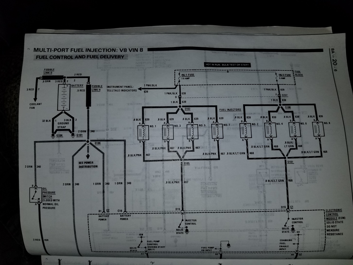
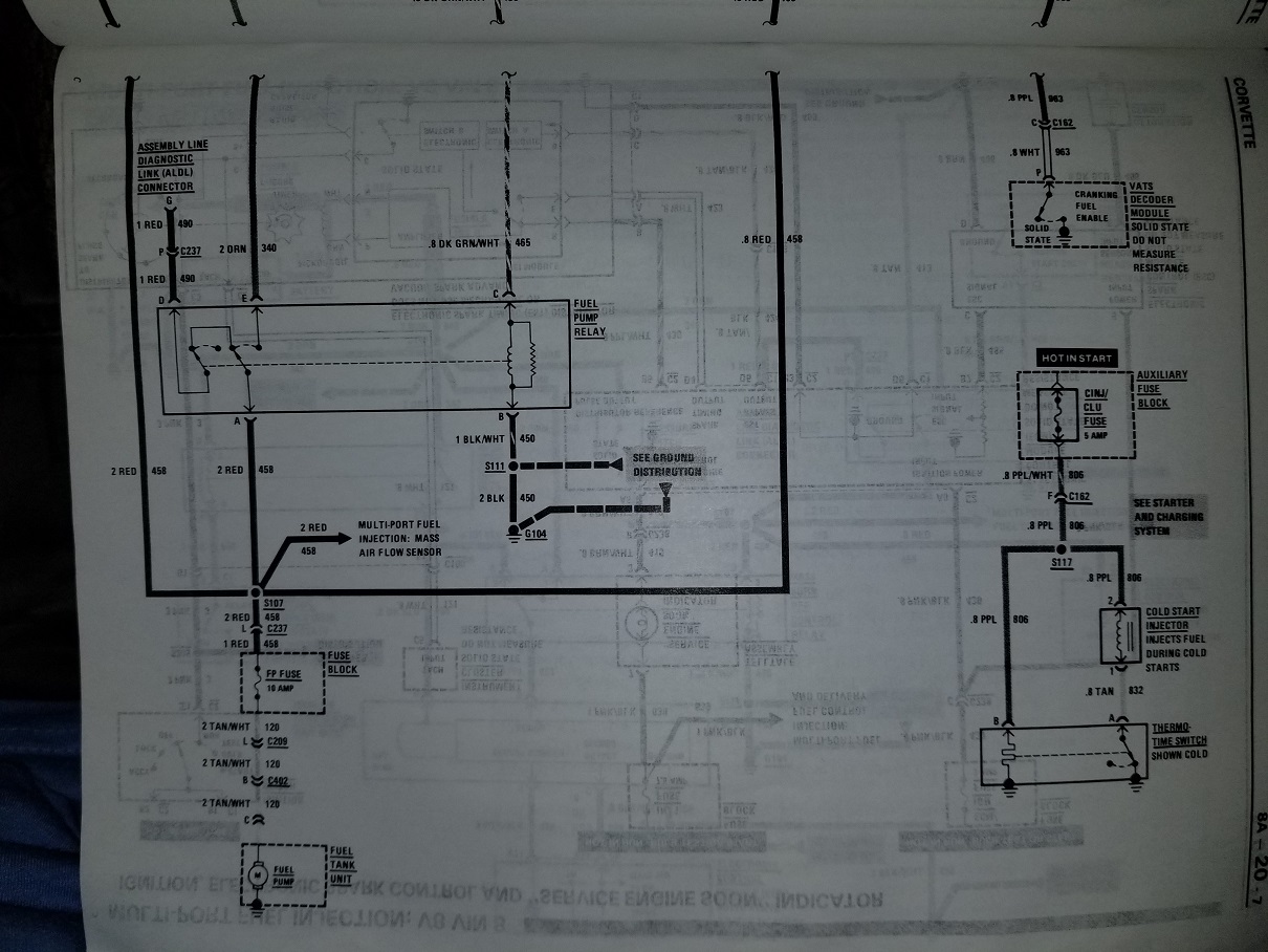
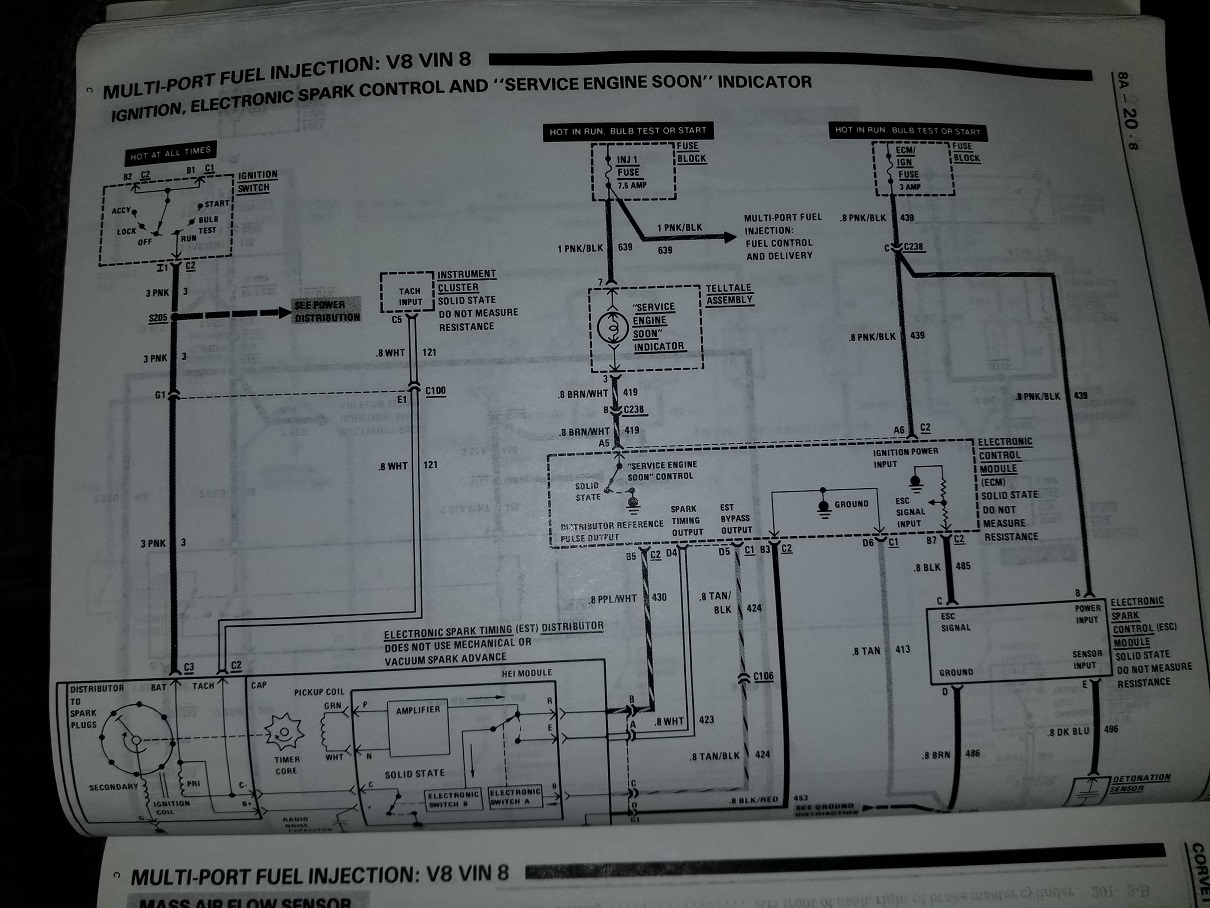
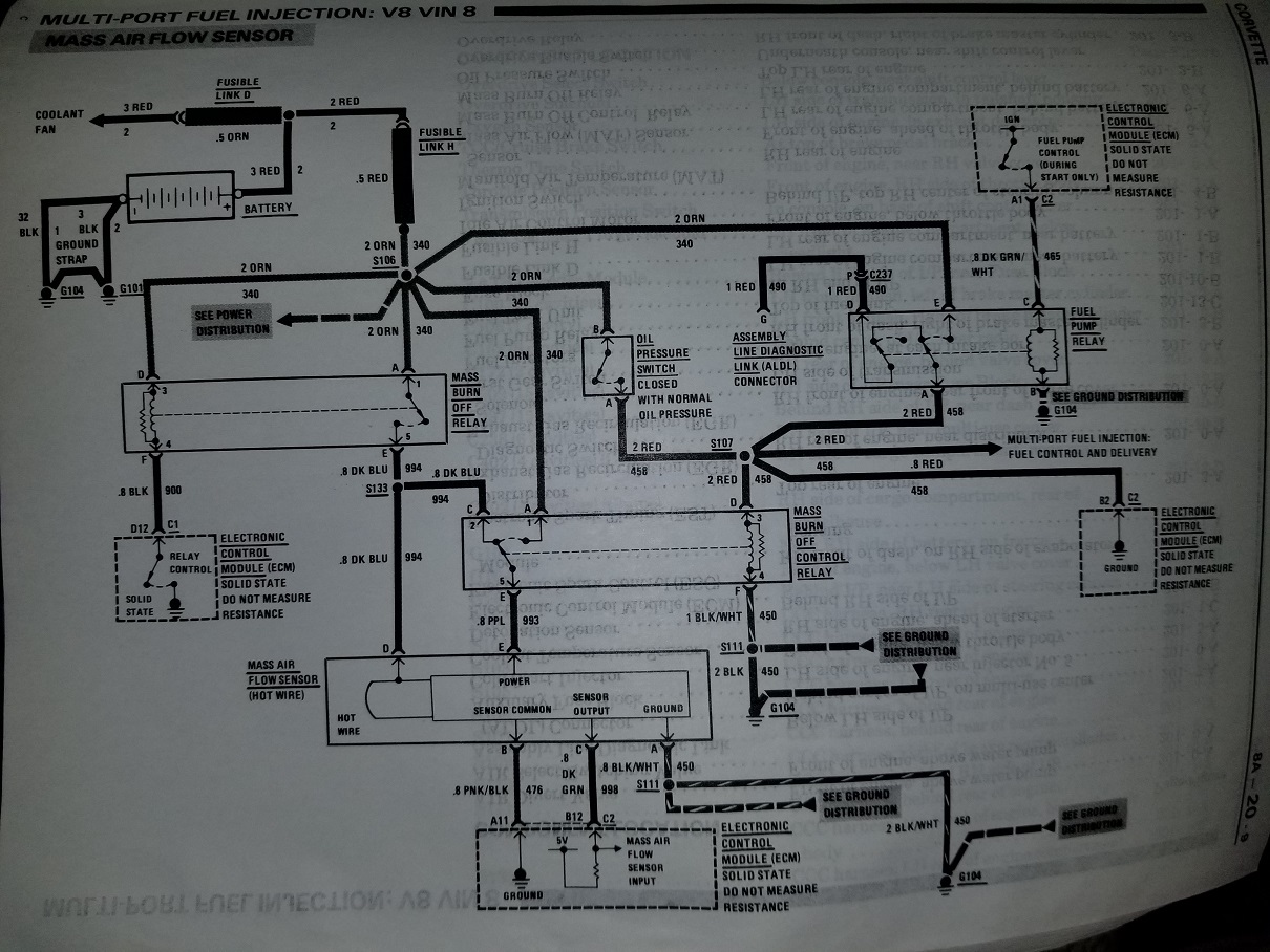
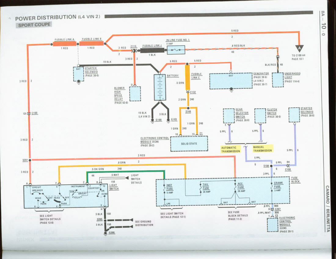
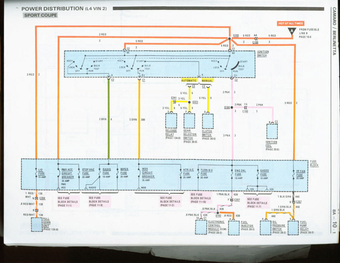
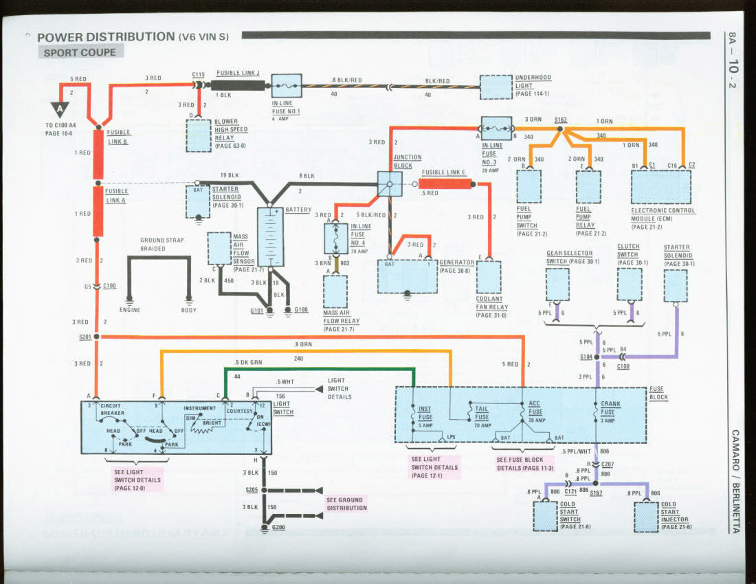
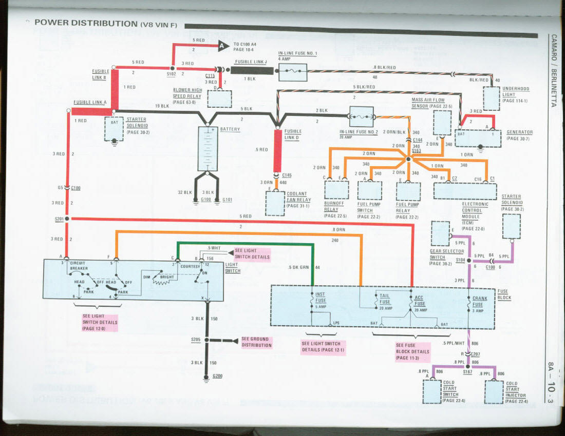
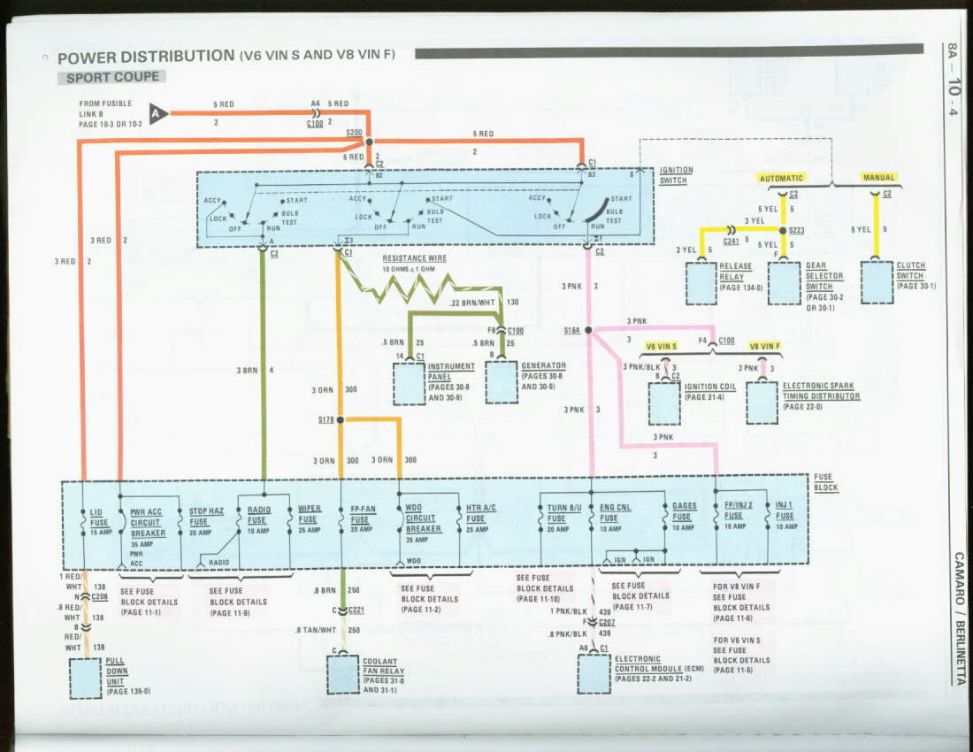
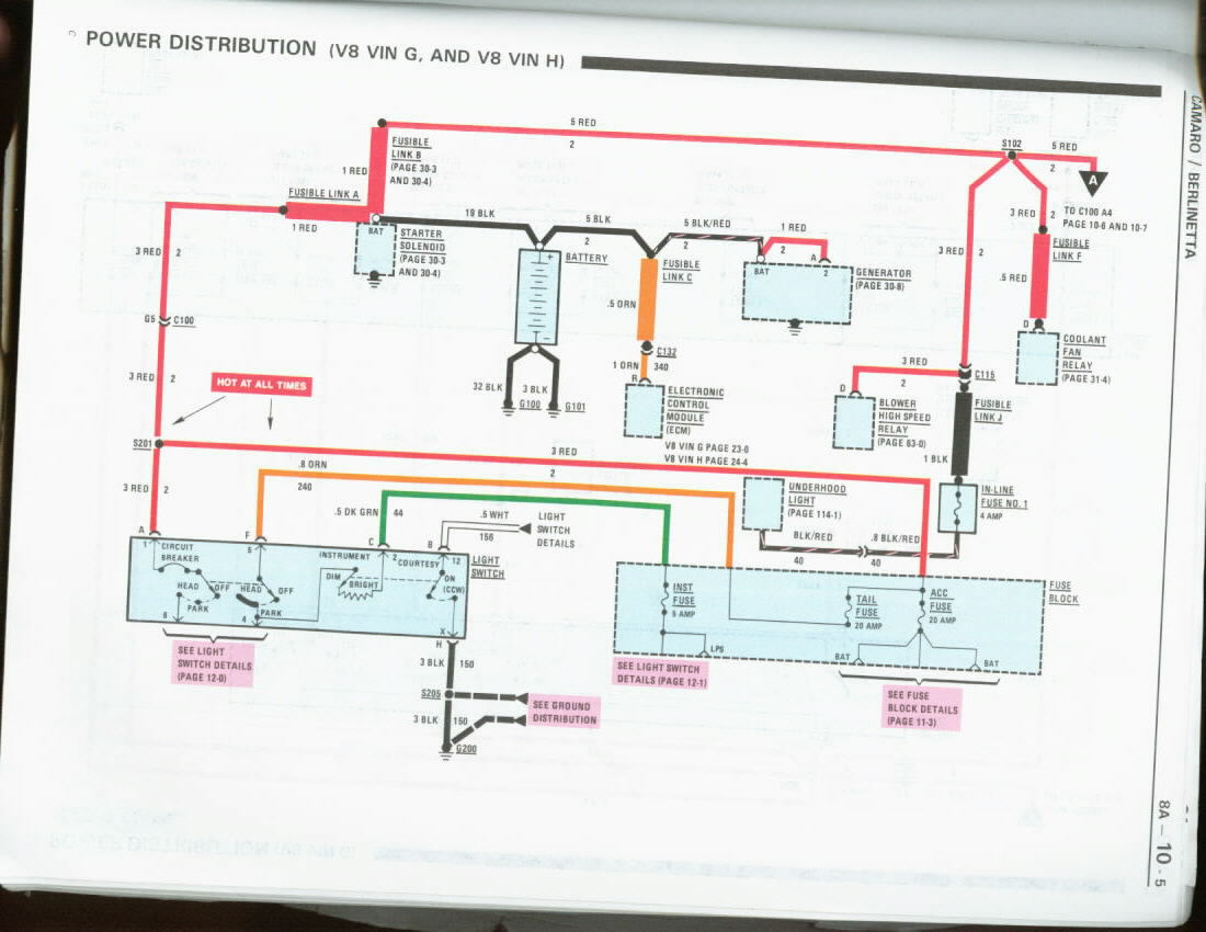
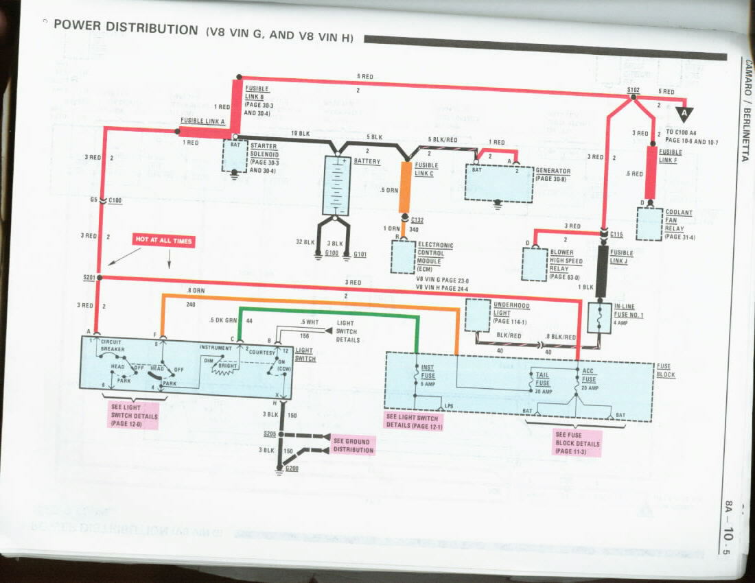
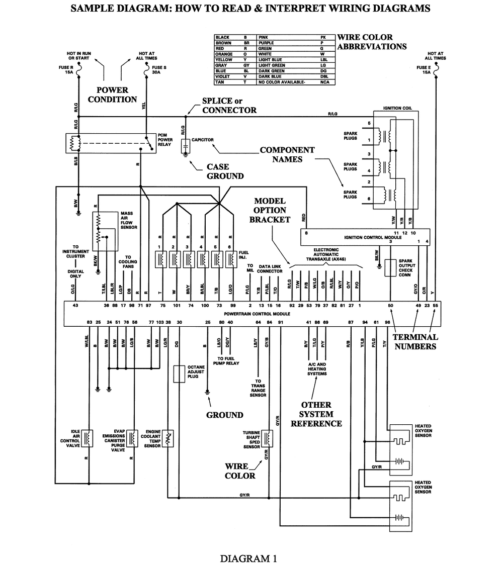
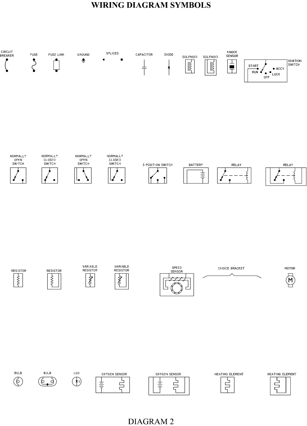
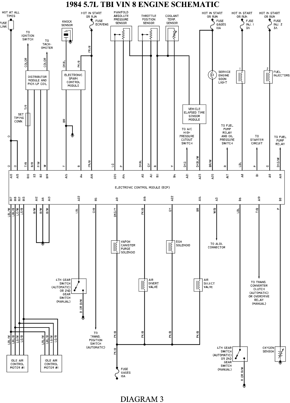
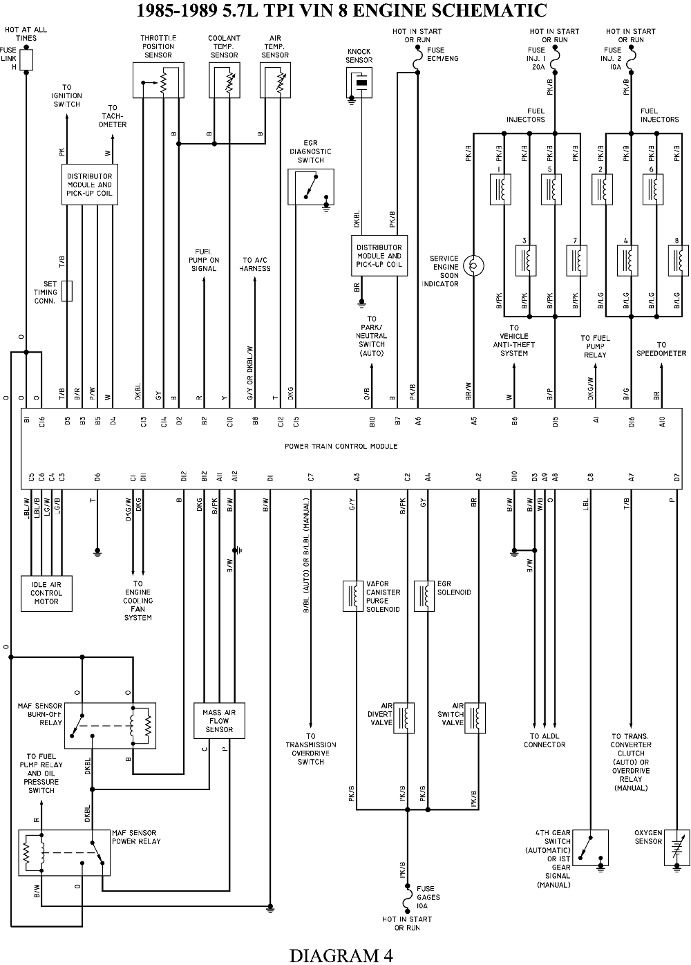
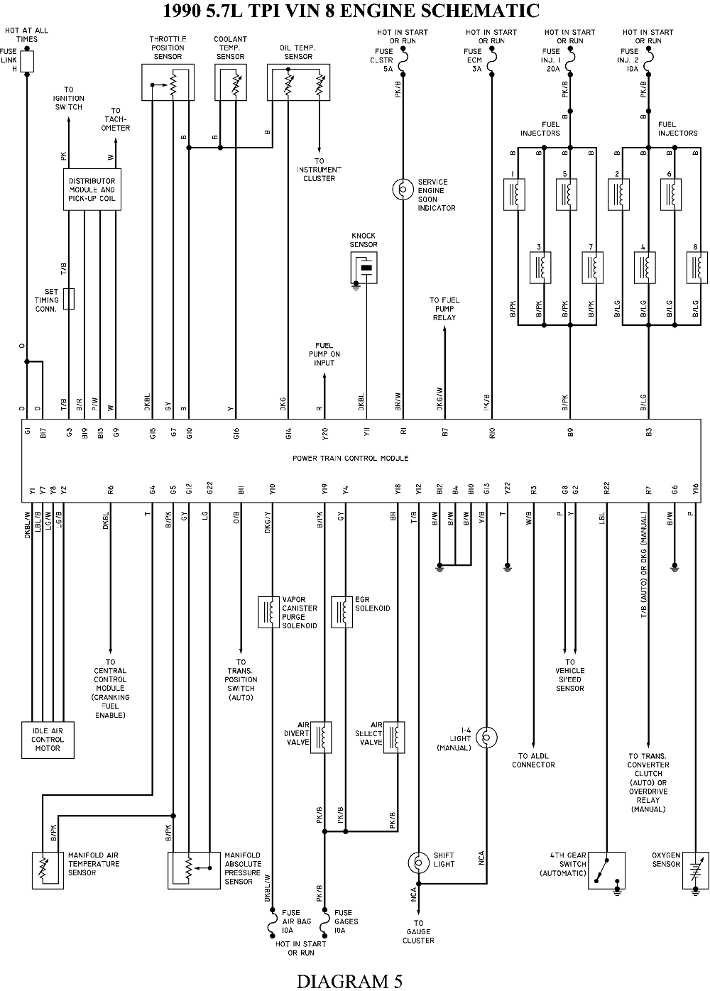
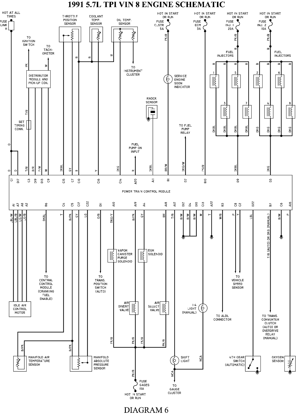
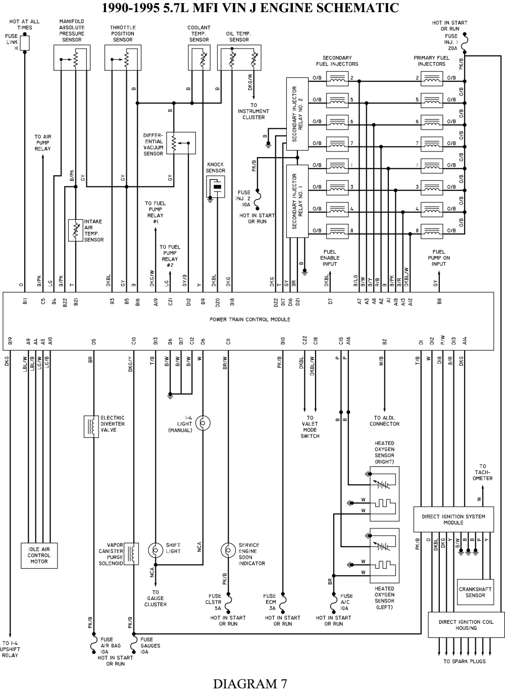
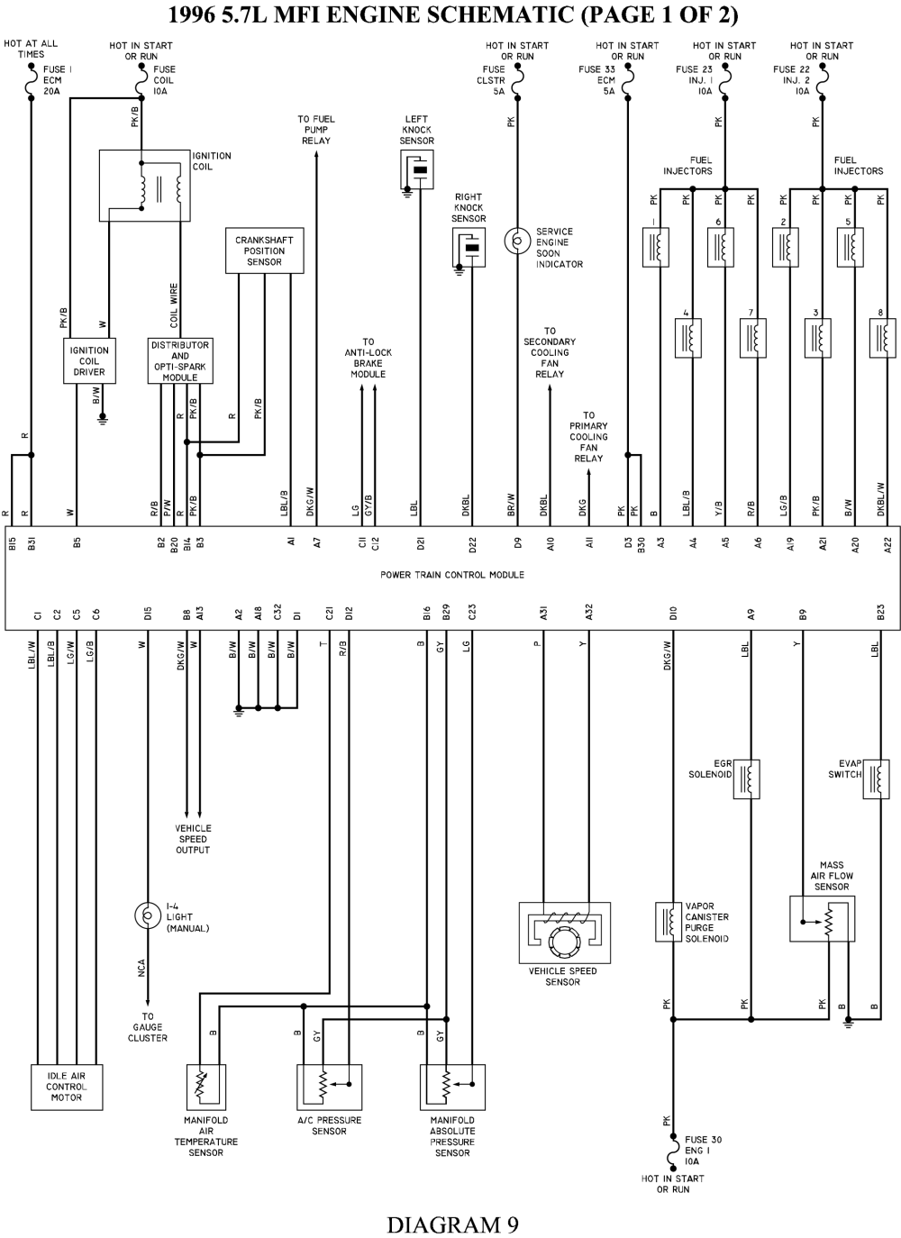
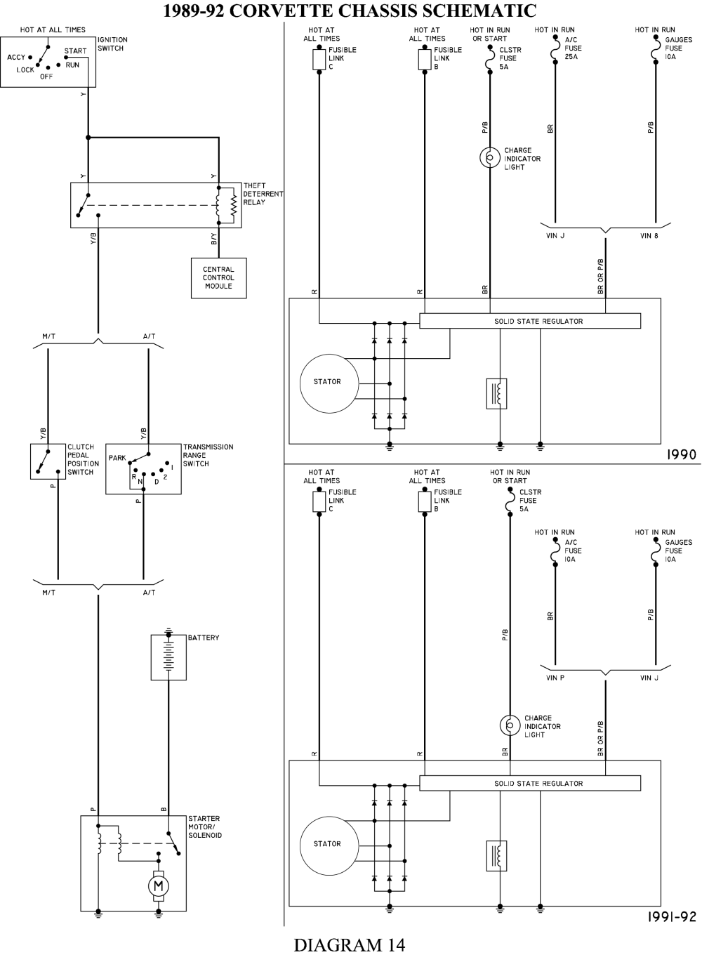
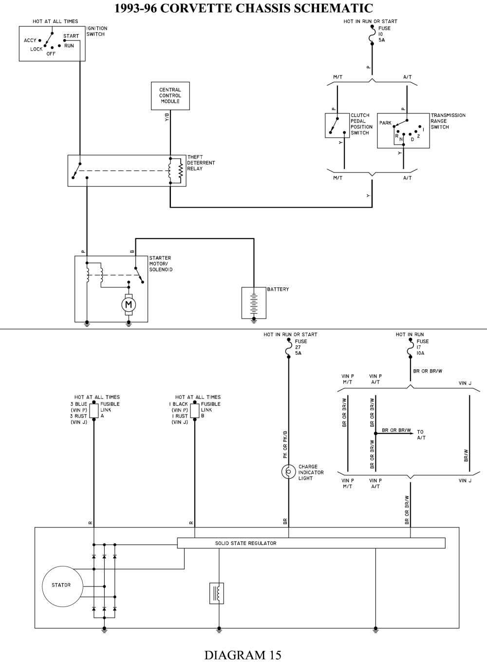
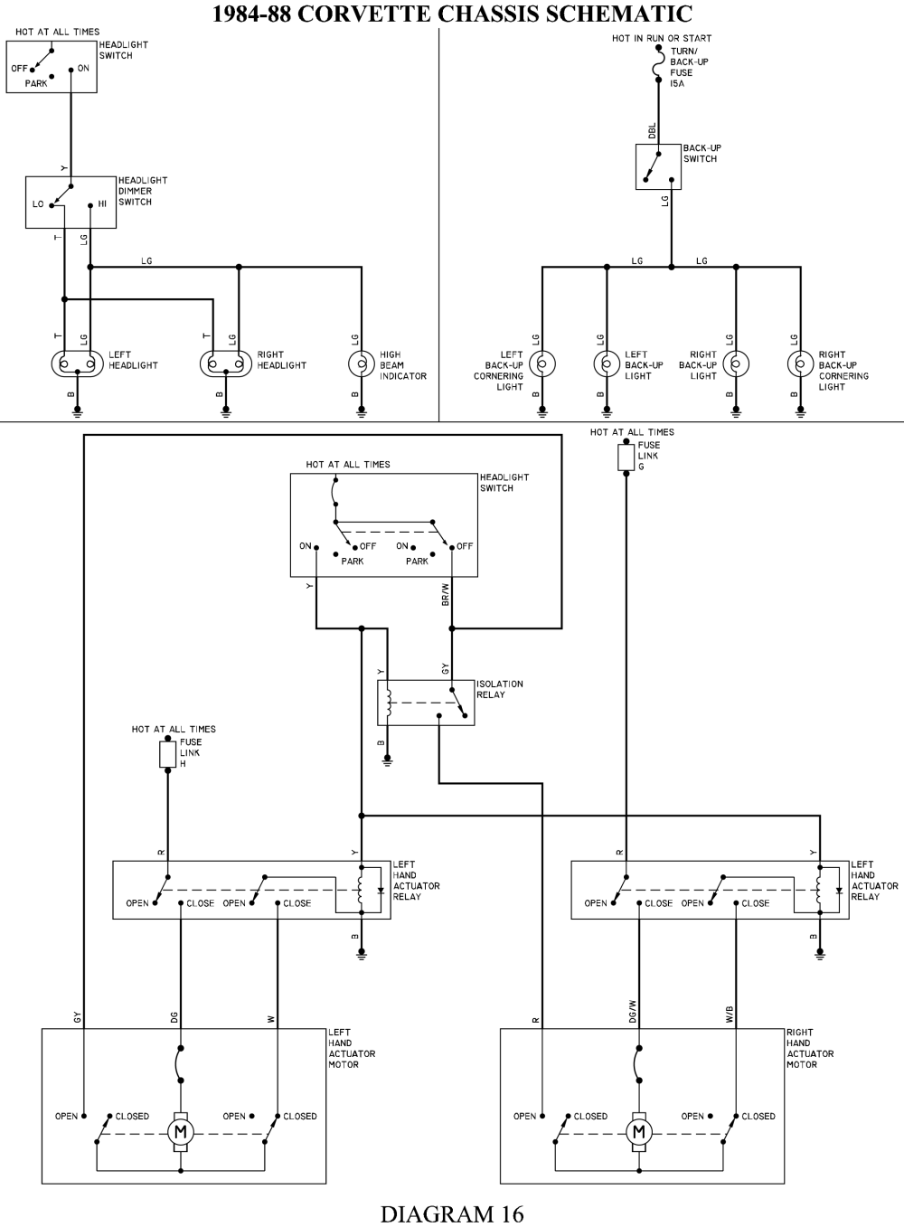
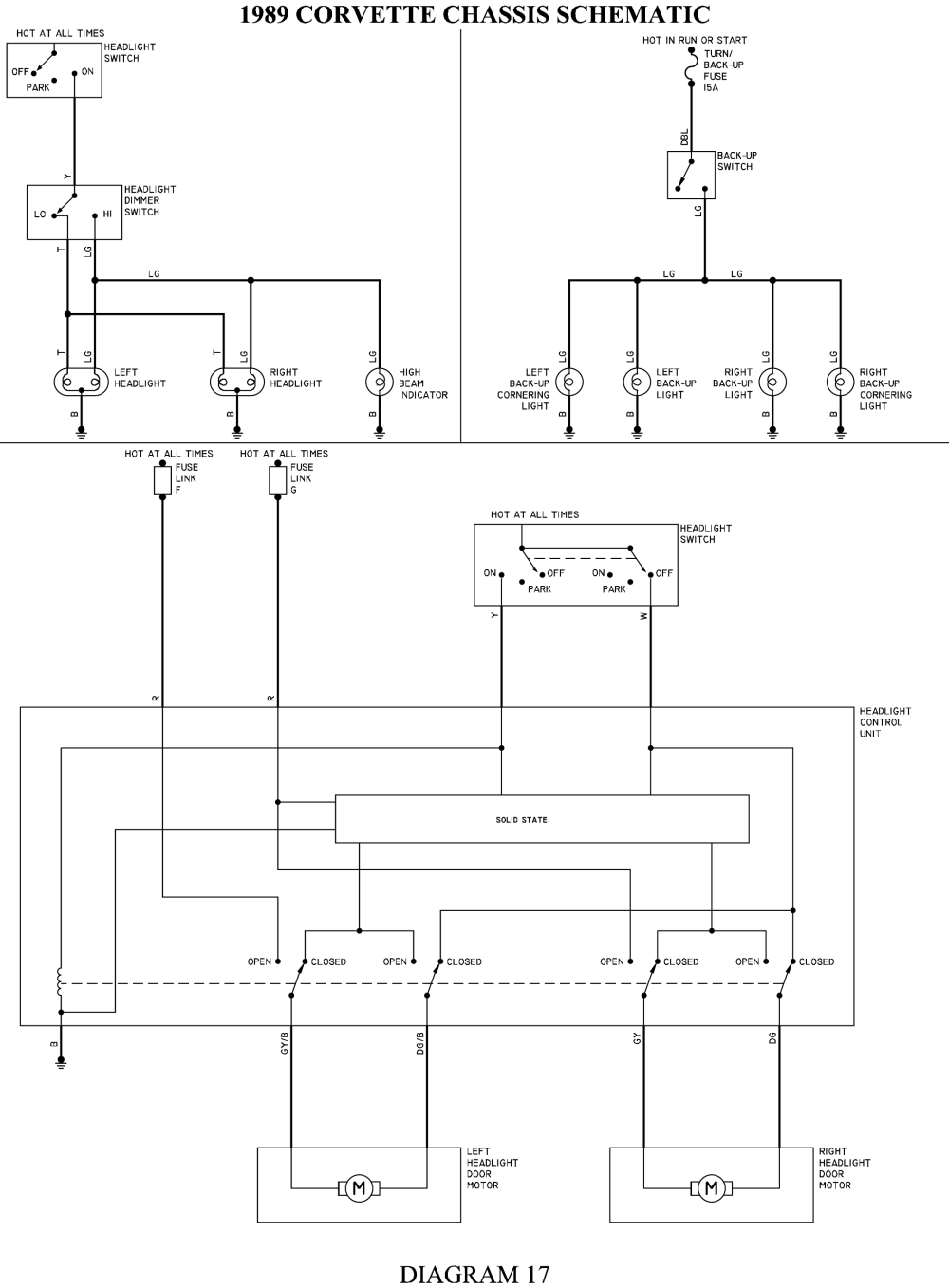
yes I know theres a huge tendency to want to skip over the posted links, thats a mistake simply because they hold a great deal of useful related info, and may hold the exact key to your particular problem
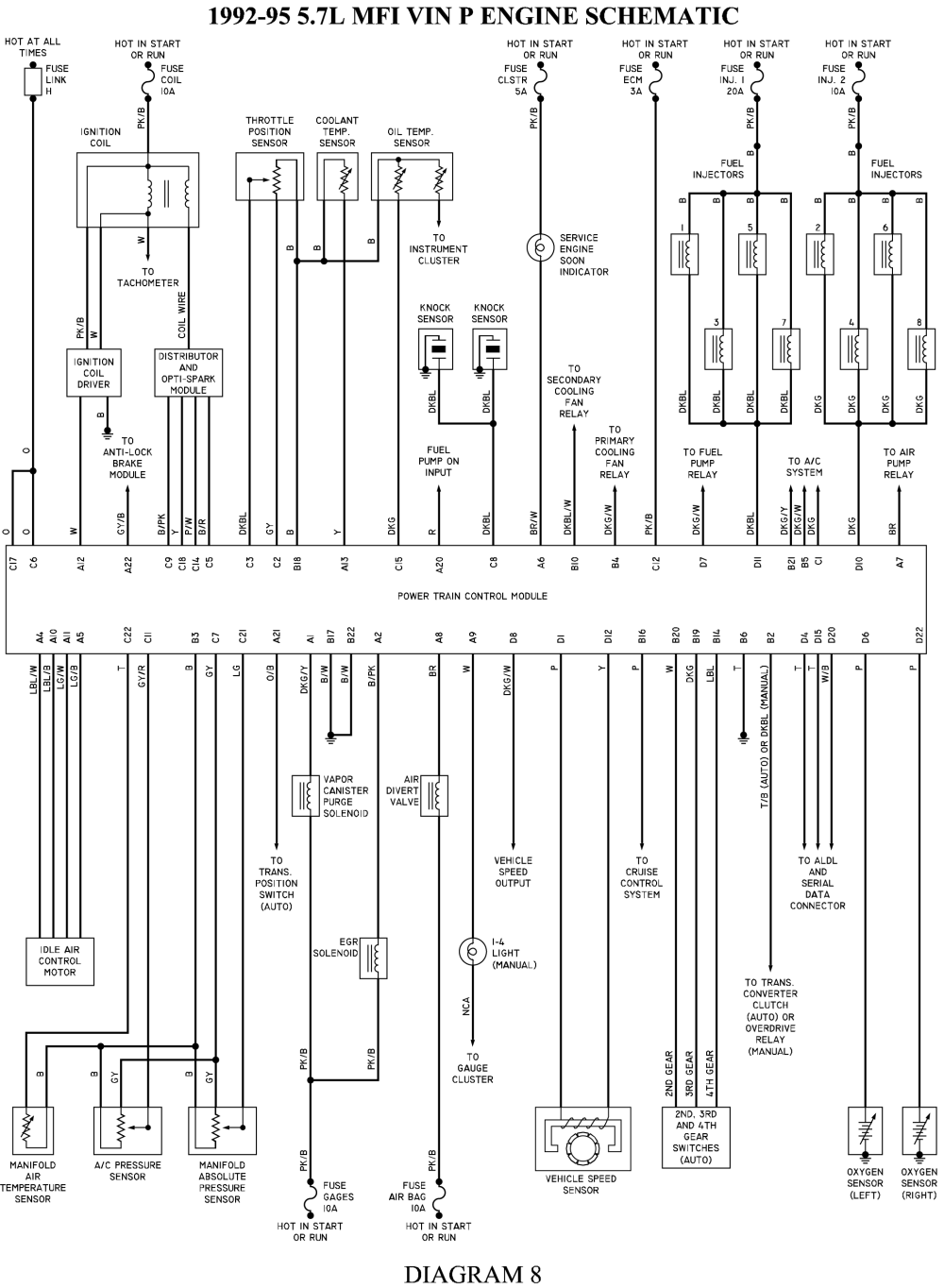
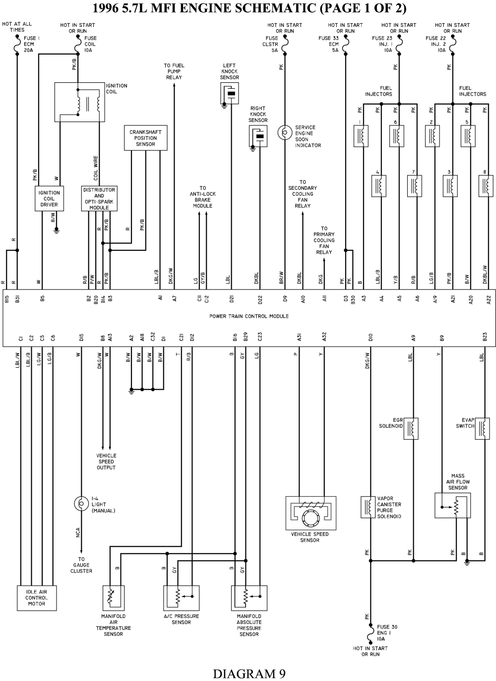
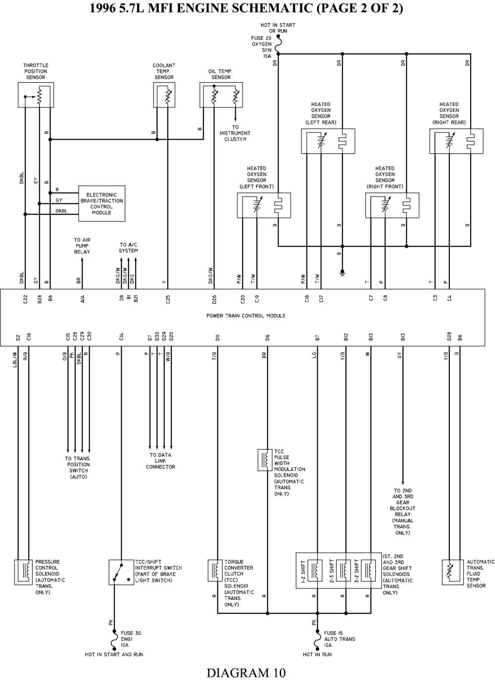
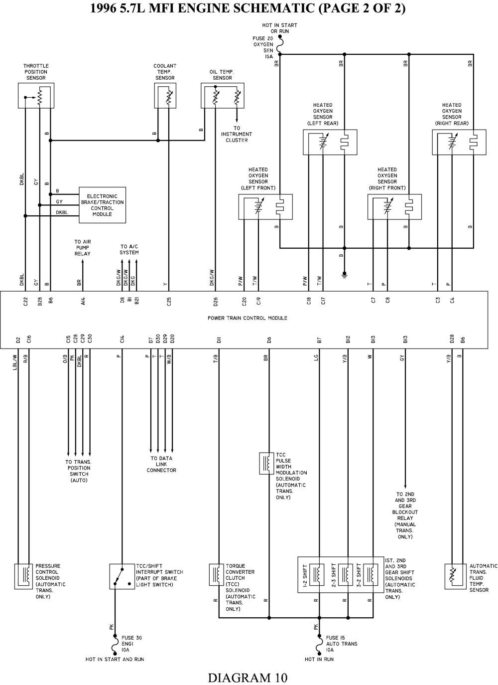
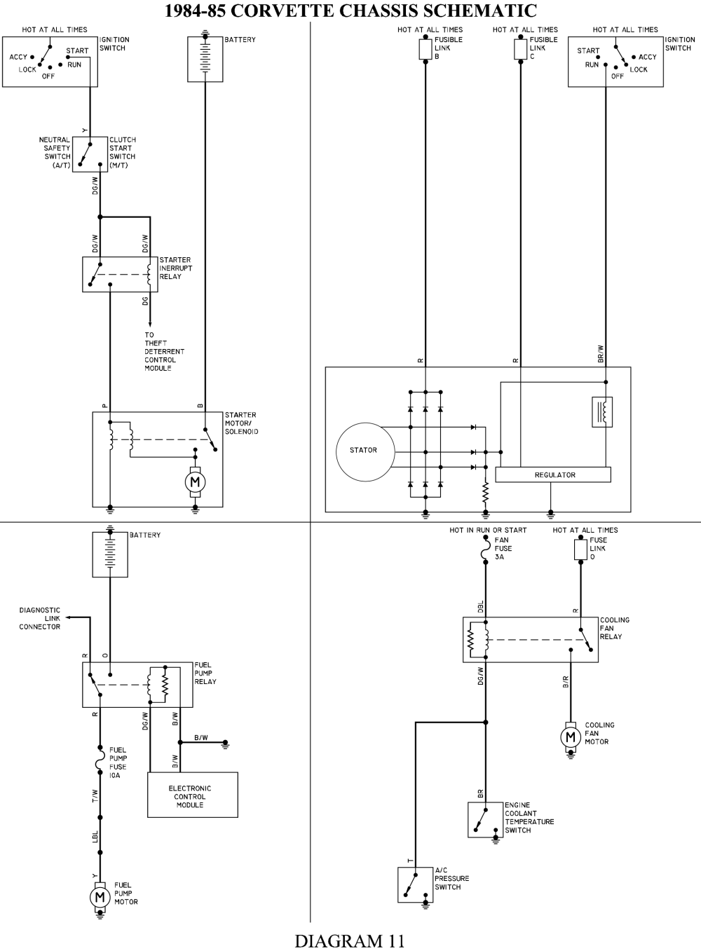
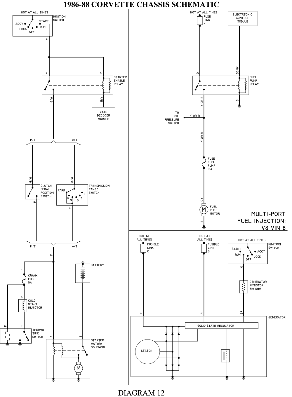
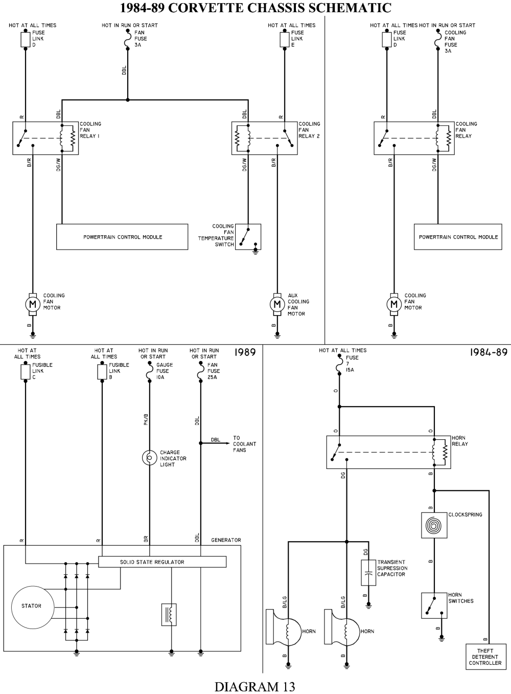
if you need a detailed wiring diagram the obvious first choice would be the purchase of the cars factory shop manual
http://www.helminc.com/helm/homepage.asp?r=https://www.google.com/
http://www.factoryrepairmanuals.com...=ON&make=Chevy&model_id=Corvette&year_id=1985
http://docrebuild.com/oosoez/8973101.html
http://www.nrjvette.com/johdotukset/?c=d;o=d
http://www.lectriclimited.com/wiring_di ... rvette.htm
http://www.nrjvette.com/johdotukset/?C=D;O=D
http://www.chevythunder.com/Flow chart index.htm
http://www.tocmp.com/tOCMP/wiring/5765w ... tindex.htm
viewtopic.php?f=70&t=986&p=1738&hilit=electrical+connectors#p1738
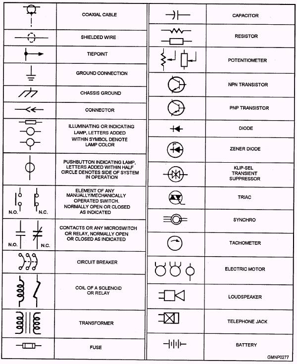
http://www.epemag.net/how-to-read-circuit-diagrams.html
http://www.12voltresource.com/
viewtopic.php?f=70&t=1443&p=3211#p3211
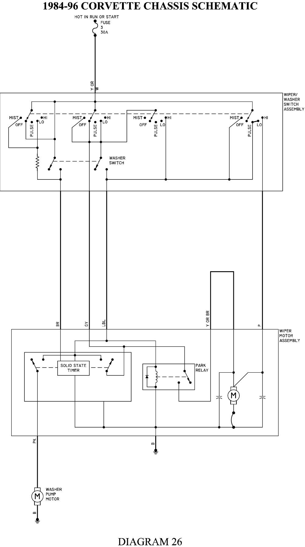
http://members.shaw.ca/dankai/Windshield Wipers.pdf
http://garage.grumpysperformance.co...-engine-harness-integration.11148/#post-49939
finding that elusive connector or pigtail that was damaged or melted can be a P.I.T.A. but these links may help
http://www.crateenginedepot.com/pdfs/Pigtails.pdf
https://www.acdelco.com/parts/wires-cables
https://www.wiringproducts.com/general-motors-engine-connectors
http://terminalsupplyco.com/Store/Default.aspx?CAT=SF060030
https://www.bwdbrand.com/media/2827/bw11211-illustrated-connector-guide.pdf
https://www.underhoodservice.com/acdelco-releases-newly-integrated-pigtail-catalog/
https://findpigtails.com/
https://www.amazon.com/gm-pigtail/s?k=gm+pigtail
RAYQUAYLE POSTED THIS INFO
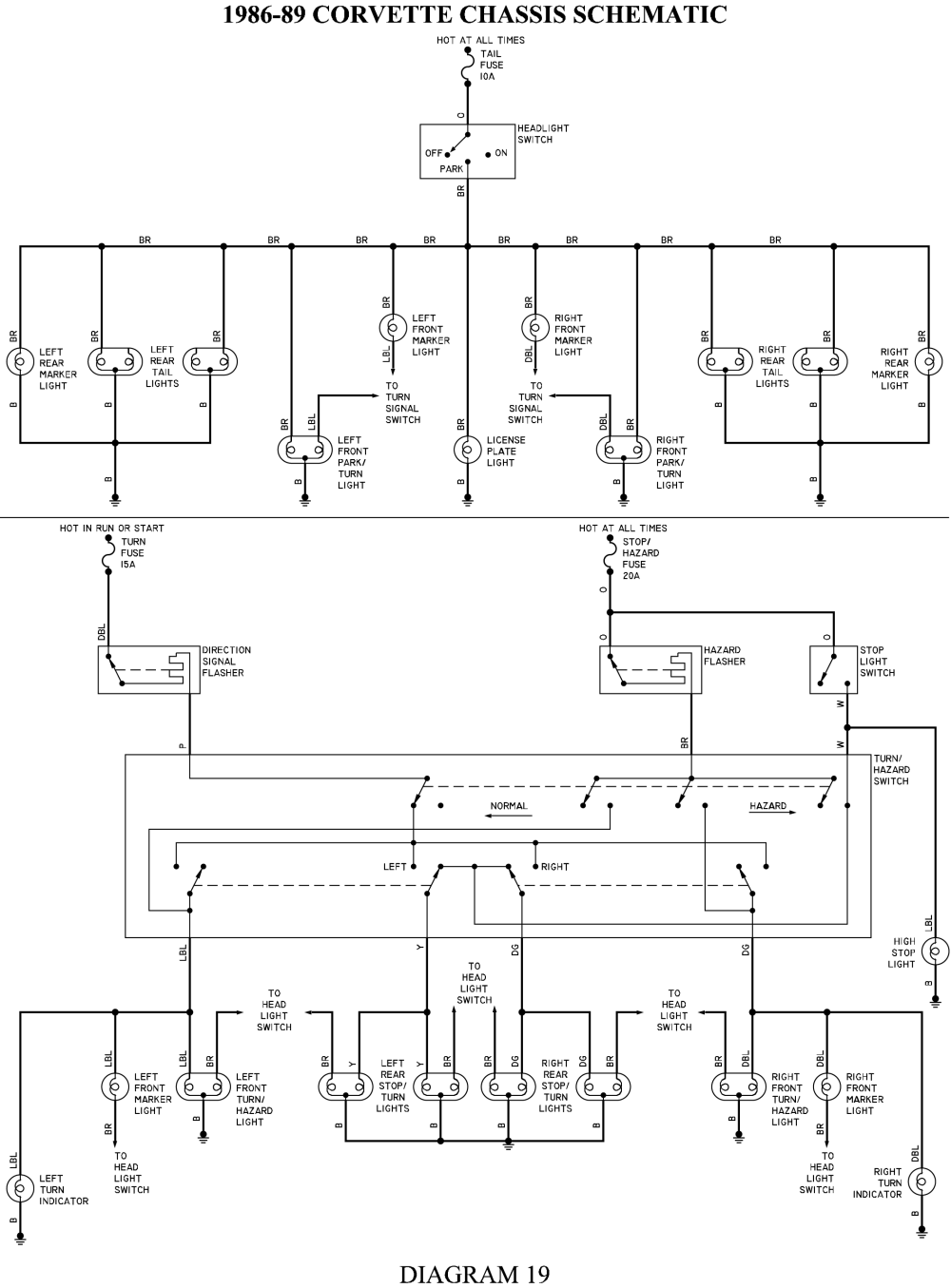
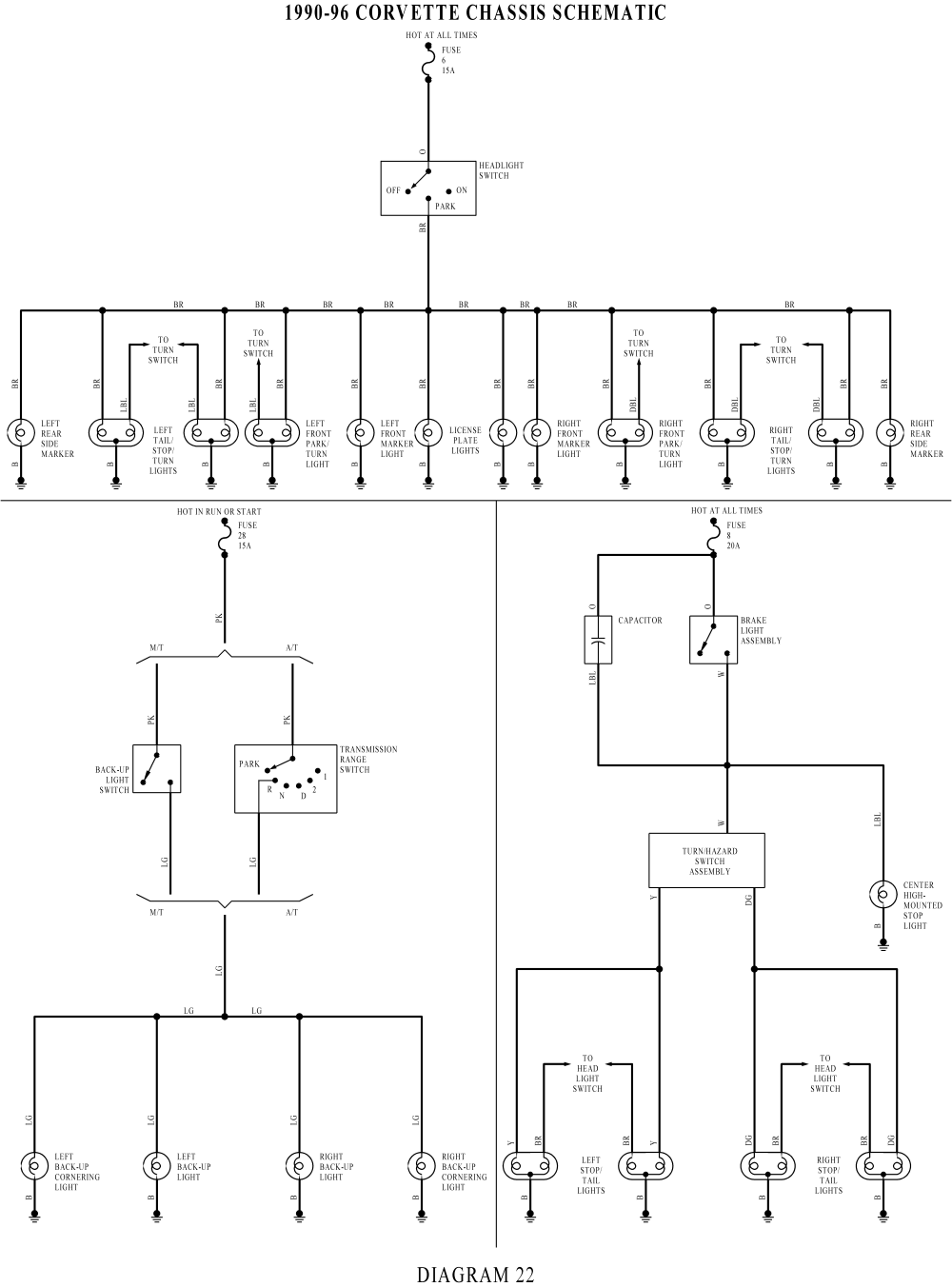
They are very similar. The Multi-function Switch is the turn signal switch or Directional Signal/Hazard Warning Switch Assembly in the attached schematic. Operates turn, hazzard and high beams.
The Stop Lamp Switch is always connected to the rear lights, unless a turn is requested. At that point the Stop Lamp Switch connection is broken and the requested turn (Left or Right) is connected to the Direction Signal Flasher. The other side remains connected to the Stop Lamp Switch. This way if a right turn is selected, the contacts in the Directional Signal/Hazard Warning Switch Assembly that are between pins M, N and P are the ones we are interested in. Pin P is the input from the Stop Lamp Switch and supplies battery voltage when the brake pedal is depressed (Stop Lamp Switch closes) to the OFF contact, because a right turn was selected in our example, pin N is no longer connected to the OFF contact, but is now connected to the RIGHT contact and pin L, which goes to the Direction Signal Flasher and the right tail lights flash. Pin M is still connected to the OFF contact and the left tail lights light solid as long as the brake pedal is depressed. Obviously if a left turn is selected, this is reversed and if no turn is selected, both pins (M and N) remain connected to the OFF contact and all tail lights light solid if the brake pedal is depressed.
To troubleshoot the Stop Lamp Switch (Brake Light Switch), verify battery voltage to ground from the orange wire. It looks like you did that with your test light and it was good. Now check for battery voltage between ground and the white wire. Same as the first test, but move the one end of the test light from the orange wire to the white wire and push the brake pedal. If no light, it could be out of adjustment. Try the tests again with the switch unmounted. The orange and white wires are connected to normally closed contacts and the brake pedal opens them when in the at rest position (brake off) blocking current flow to the Directional Signal/Hazard Warning Switch Assembly and no brake lights until you press the brake pedal and the switch is allowed to close and the current can again flow to the lights. This means that with the switch connected, but not mounted, the contacts should be closed and the test light should light on both the orange and white and the brake lights should be on.
Try it and see what happens. If not we'll move on from there.


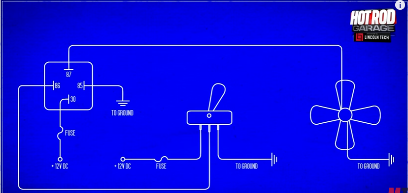
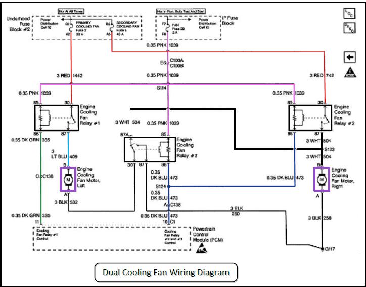
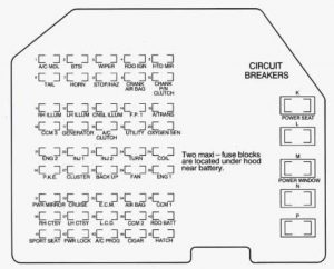
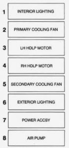
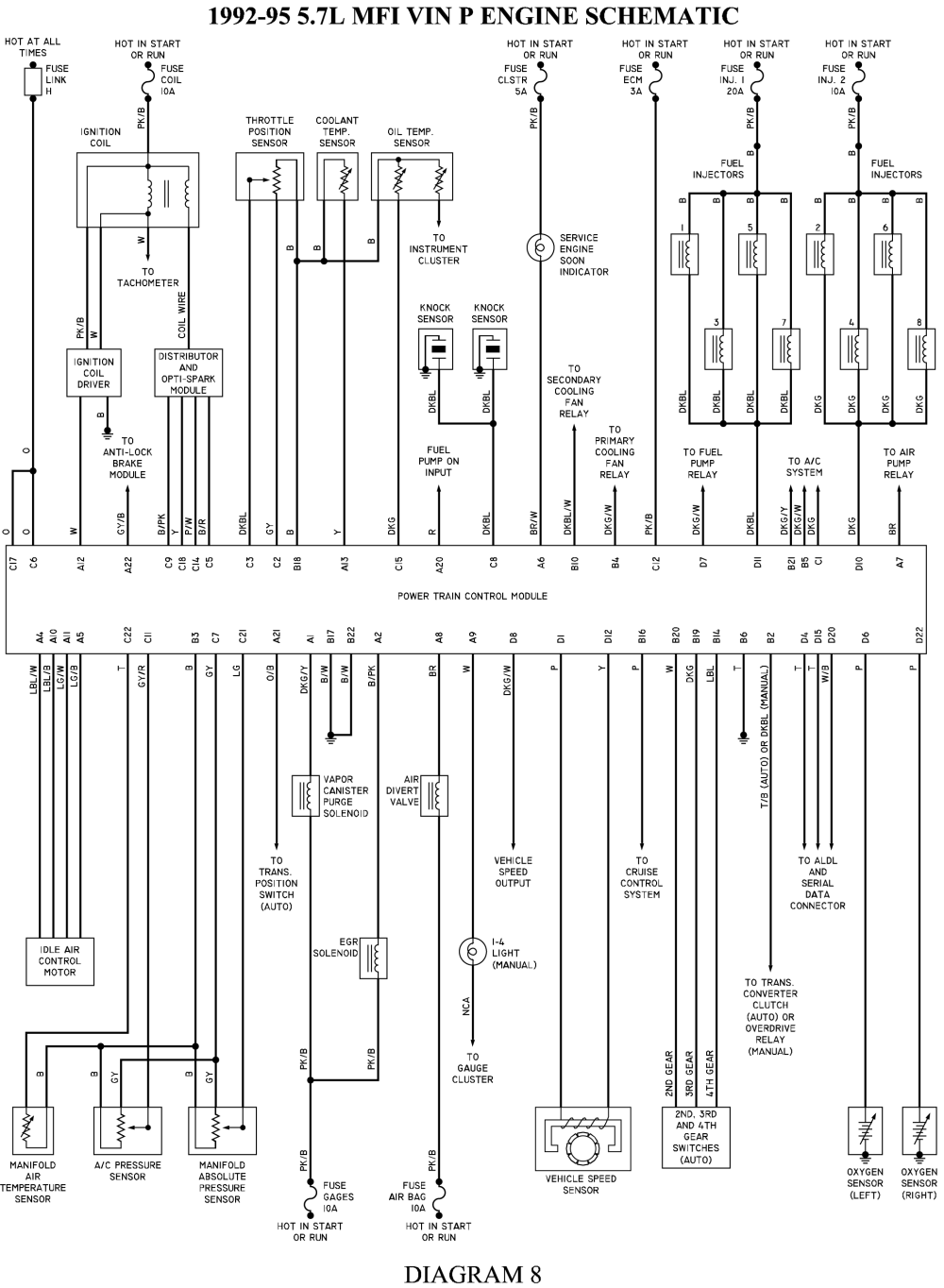
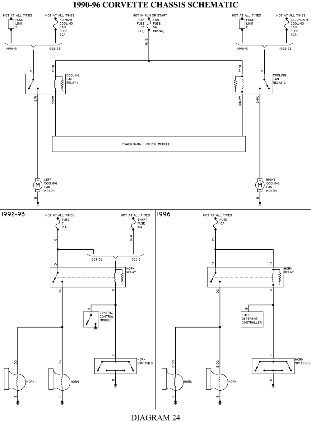
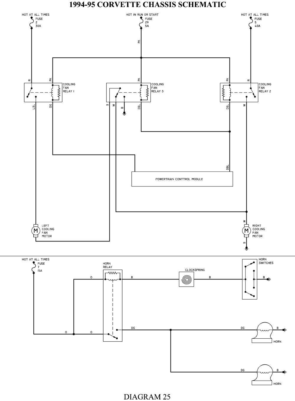
Your Corvette’s main cooling fan is controlled by the PCM. The PCM sends a ground signal to the fan relay when it sees the desired temperature to run the fan has been met. You need to check the relay and make sure you are getting your battery 12V and ignition 12V when the key is on. With the key on, jump the ground wire in the relay, if the fan turns on you have an issue in the PCM and it may be time for a rebuild. If it does not turn on then your problem lies in the fan circuit between the relay and the fans.
if you need a detailed wiring diagram the obvious first choice would be the purchase of the cars factory shop manual
http://www.helminc.com/helm/homepage.asp?r=https://www.google.com/
http://www.factoryrepairmanuals.com...=ON&make=Chevy&model_id=Corvette&year_id=1985
http://docrebuild.com/oosoez/8973101.html
http://www.nrjvette.com/johdotukset/?c=d;o=d
http://www.lectriclimited.com/wiring_di ... rvette.htm
http://www.nrjvette.com/johdotukset/?C=D;O=D
http://www.chevythunder.com/Flow chart index.htm
http://www.tocmp.com/tOCMP/wiring/5765w ... tindex.htm
viewtopic.php?f=70&t=986&p=1738&hilit=electrical+connectors#p1738
http://www.epemag.net/how-to-read-circuit-diagrams.html
http://www.12voltresource.com/
viewtopic.php?f=70&t=1443&p=3211#p3211
http://members.shaw.ca/dankai/Windshield Wipers.pdf
http://garage.grumpysperformance.co...-engine-harness-integration.11148/#post-49939
finding that elusive connector or pigtail that was damaged or melted can be a P.I.T.A. but these links may help
http://www.crateenginedepot.com/pdfs/Pigtails.pdf
https://www.acdelco.com/parts/wires-cables
https://www.wiringproducts.com/general-motors-engine-connectors
http://terminalsupplyco.com/Store/Default.aspx?CAT=SF060030
https://www.bwdbrand.com/media/2827/bw11211-illustrated-connector-guide.pdf
https://www.underhoodservice.com/acdelco-releases-newly-integrated-pigtail-catalog/
https://findpigtails.com/
https://www.amazon.com/gm-pigtail/s?k=gm+pigtail
RAYQUAYLE POSTED THIS INFO
They are very similar. The Multi-function Switch is the turn signal switch or Directional Signal/Hazard Warning Switch Assembly in the attached schematic. Operates turn, hazzard and high beams.
The Stop Lamp Switch is always connected to the rear lights, unless a turn is requested. At that point the Stop Lamp Switch connection is broken and the requested turn (Left or Right) is connected to the Direction Signal Flasher. The other side remains connected to the Stop Lamp Switch. This way if a right turn is selected, the contacts in the Directional Signal/Hazard Warning Switch Assembly that are between pins M, N and P are the ones we are interested in. Pin P is the input from the Stop Lamp Switch and supplies battery voltage when the brake pedal is depressed (Stop Lamp Switch closes) to the OFF contact, because a right turn was selected in our example, pin N is no longer connected to the OFF contact, but is now connected to the RIGHT contact and pin L, which goes to the Direction Signal Flasher and the right tail lights flash. Pin M is still connected to the OFF contact and the left tail lights light solid as long as the brake pedal is depressed. Obviously if a left turn is selected, this is reversed and if no turn is selected, both pins (M and N) remain connected to the OFF contact and all tail lights light solid if the brake pedal is depressed.
To troubleshoot the Stop Lamp Switch (Brake Light Switch), verify battery voltage to ground from the orange wire. It looks like you did that with your test light and it was good. Now check for battery voltage between ground and the white wire. Same as the first test, but move the one end of the test light from the orange wire to the white wire and push the brake pedal. If no light, it could be out of adjustment. Try the tests again with the switch unmounted. The orange and white wires are connected to normally closed contacts and the brake pedal opens them when in the at rest position (brake off) blocking current flow to the Directional Signal/Hazard Warning Switch Assembly and no brake lights until you press the brake pedal and the switch is allowed to close and the current can again flow to the lights. This means that with the switch connected, but not mounted, the contacts should be closed and the test light should light on both the orange and white and the brake lights should be on.
Try it and see what happens. If not we'll move on from there.


Your Corvette’s main cooling fan is controlled by the PCM. The PCM sends a ground signal to the fan relay when it sees the desired temperature to run the fan has been met. You need to check the relay and make sure you are getting your battery 12V and ignition 12V when the key is on. With the key on, jump the ground wire in the relay, if the fan turns on you have an issue in the PCM and it may be time for a rebuild. If it does not turn on then your problem lies in the fan circuit between the relay and the fans.
Last edited by a moderator:

