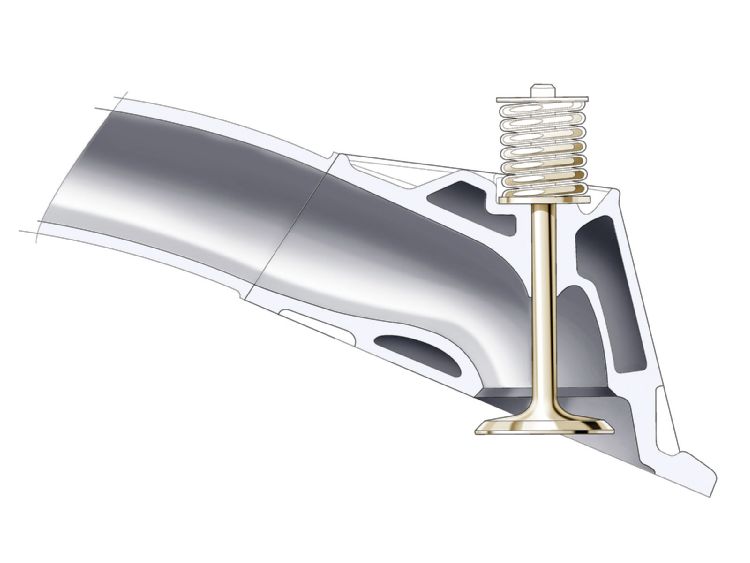
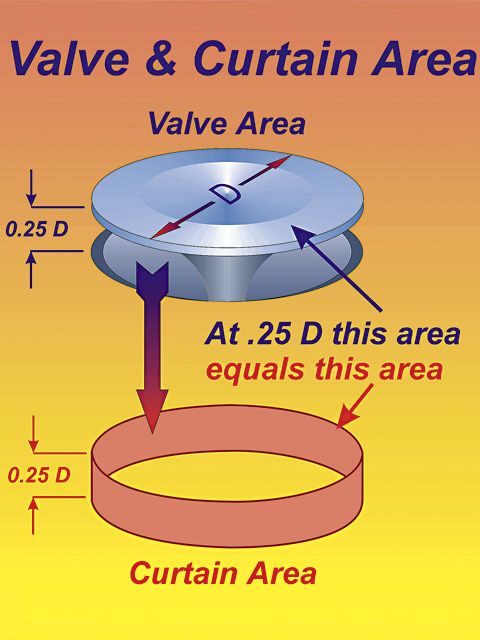
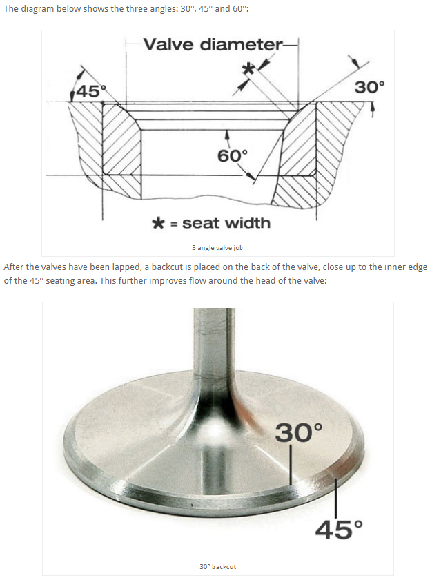
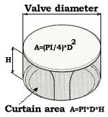
for a valve to function correctly it needs to both seal completely when seated against the head and allow efficient flow between the valve seat and underside of the valve as it lifts off its seat, the curtain area( that's BASICALLY, the distance the valve is off its seat times the valve circumference) gives you the potential area of flow, but obviously the area tangent to the cylinder wall and combustion chamber shrouding will flow less in most cases than flow directed towards the area more to the center of the cylinder.
air flow tends to develop turbulence, that lowers the flow volume if its forced to change direction over a sharp machined edge, if the change exceeds about 15 degrees, that's why most valve seat areas are multiples of no more than 15 degree changes in angle.
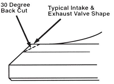
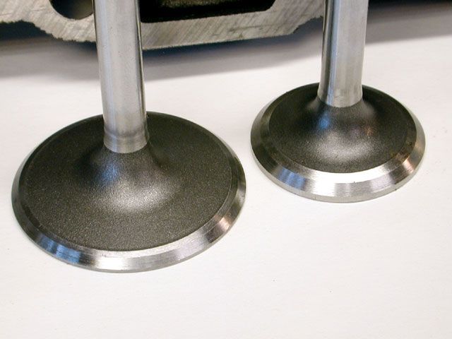
back cutting the valve tends to smooth flow thru the curtain area at low lifts and its not unusually to pick up several horsepower doing so
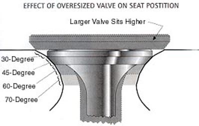
as a valve wears and the valve seats wear the seal tends to slowly degrade, but because both the valve edge and the valve seat angles form concentric cones the valve tends to seat slightly deeper and stays sealed to compensate for minor wear.
naturally the port and bowl area configuration under the valve seat and the intake and exhaust port size , length, cross section and pressure and angle effect the flow rates thru the valves.
read this related thread and sub linked info
http://garage.grumpysperformance.com/index.php?threads/valve-seat-angles-and-air-flow.8460/
http://garage.grumpysperformance.com/index.php?threads/valve-seat-runout.15104/#post-86003
http://garage.grumpysperformance.co...video-with-info-worth-watching-through.15999/
http://garage.grumpysperformance.co...alves-and-polishing-combustion-chambers.2630/
its been my experience that a properly done valve job with 3-5 angles and its the port throat and valve guide area under the valve,
[
that is a huge factor in its potential flow, but remember the header scavenging and compression and cam timing all effect the potential results, while the article may promote the 50 Deg valve seat angle a change in cam timing port shape or exhaust scavenging or rocker ratio, various porting tech, piston too combustion chamber mods, heat reflective coating, merge collectors , would have a more noticeable effect on the engines power curve in my opinion.
theres a reason the early SBC 23 degree heads with similar valve size to the later 18 degree heads can,t keep up, and its not the valve seat angles, theres a reason the later vortec heads with similar port volume and valve size to the mildly ported corvette fuelie heads out flow those early heads that were designed in the 1960s , and its not the valve seat angles!
and the biggest reason the 50 degree valve seat angle is not commonly used is long term durability, valves wear and seats wear and as the valve sinks deeper into the heads combustion chamber flow is reduced , now on a race engine that will be dis-assembled every season that may not be a huge issue, but if you expect to get 50K-100K miles its something you'll want to think through.
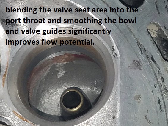
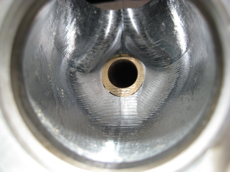
blending the valve seat into the port throat with a 3-5 degree multi angle valve job, and porting the bowl area and valve guides,will have far more effect on power than a couple degree change in valve seat angle

read this related thread and sub linked info
http://garage.grumpysperformance.com/index.php?threads/valve-seat-angles-and-air-flow.8460/
http://garage.grumpysperformance.co...alves-and-polishing-combustion-chambers.2630/
Here is an excerpt from an AERA TB,,
===================
Exhaust Valve Guide Caution On
1965-98 GM Big Block Engines
These engines' valve guides were not intended as a replacement item from GM.
The guides were located into the head castings after the head was cast and
the exhaust guide is "water cooled".
The water-cooled guide also has two different size press fit diameters. Adding additional confusion to the matter, they also switched the location of the larger diameter sometime in 1985.
To determine which outside diameter guide you have and which direction to
remove an exhaust valve guide, the following procedure is suggested:
Drive the guide no more than .250" (6.35 mm) toward the valve spring side of
the head and stop. Then, measure the newly exposed area of the guide
OD next to the spring pad.
If the measurement is .620" it is the first style guide. To remove this
style guide, continue driving it toward the valve spring side of the head.
If the measurement is .616" , it is the second style guide. To remove
this style guide, you must drive it the opposite direction toward the combustion
chamber side of the head.
read the links
http://www.engr.colostate.edu/~allan/fl ... age4f.html
viewtopic.php?f=52&t=333&p=8319&hilit=flow+bench#p8319
viewtopic.php?f=38&t=1099&p=2215&hilit=+flow+bench#p2215
http://www.altsale.com/frm.htm
viewtopic.php?f=50&t=3422&p=9066#p9066
http://www.aera.org/ep/downloads/ep1/EP012008_34-40.pdf
http://garage.grumpysperformance.com/index.php?threads/how-to-lap-valve-seats.1159/#post-2362
viewtopic.php?f=52&t=8596&p=30222#p30222
http://en.wikipedia.org/wiki/Air_flow_bench
viewtopic.php?f=27&t=408&p=688&hilit=+flow+bench#p688
http://www.carcraft.com/techarticles/11 ... to_04.html
http://www.alexsparts.com/
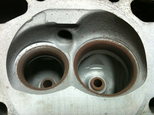
a basic but effective valve job with blended port bowl area clean -up helps flow rates
on a performance application a 5 angle valve job and back cutting the valves can add significantly to the port flow but its usually some what wasted effort on any engine with less than 240 degrees of cam duration at .050 lift, and less than 10:1 compression or one thats not designed to operate at over 6000 rpm, and generally not done
valves can be back cut to smooth low lift flow as well as ports
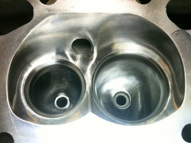
a carefully contoured and smoothed port, and bowl area under the valve tends to flow better
http://www.enginebuildermag.com/Article ... _jobs.aspx
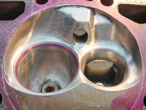
a carefully blended and unshrouded combustion chamber also helps increase flow
port and bowl configuration can drastically effect flow thru the valve
http://www.eddiesvalvegrinding.com/valve-grinding.htm
http://books.google.com/books?id=AatRNA ... ob&f=false
https://goodson.com/collections/cylinder-head-rebuilding-tools
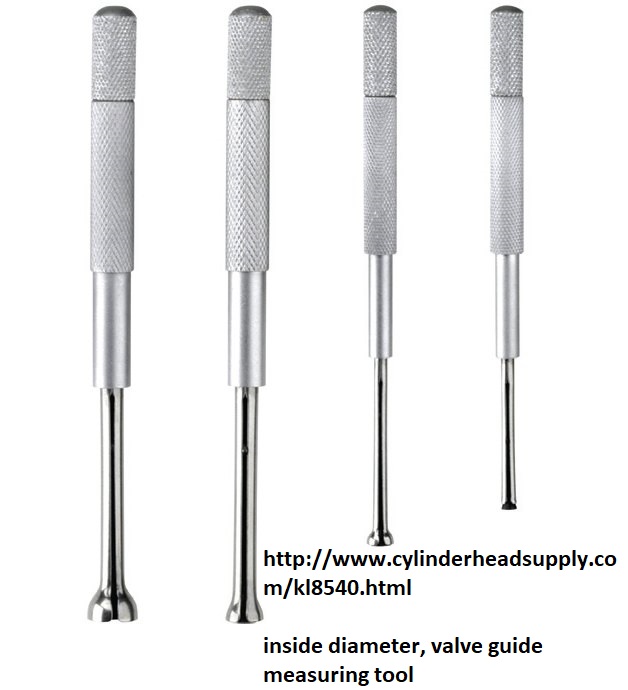
http://www.cylinderheadsupply.com/kl8540.html
HEAD TERMINOLOGY
Cylinder Head Design and Terms
By Joe Alaniz (Air Flow Technician)
ALANIZ has taken the time to hopefully educate the sports car enthusiast about certain words and procedures. So lets get started.
BACK CUT VALVE
This describes an additional angle added to the valve head to improve flow. Be aware different angles give different flow results at certain valve lifts.
BOTTOM CUT (throat cut)
The bottom cut is just as it sounds, the cut furthest into the valve-throat area. This cut opens the throat diameter to mate up with the main seating angle. On Honda B16/GSR heads, this angle has the greatest affect on mid to high valve lifts.
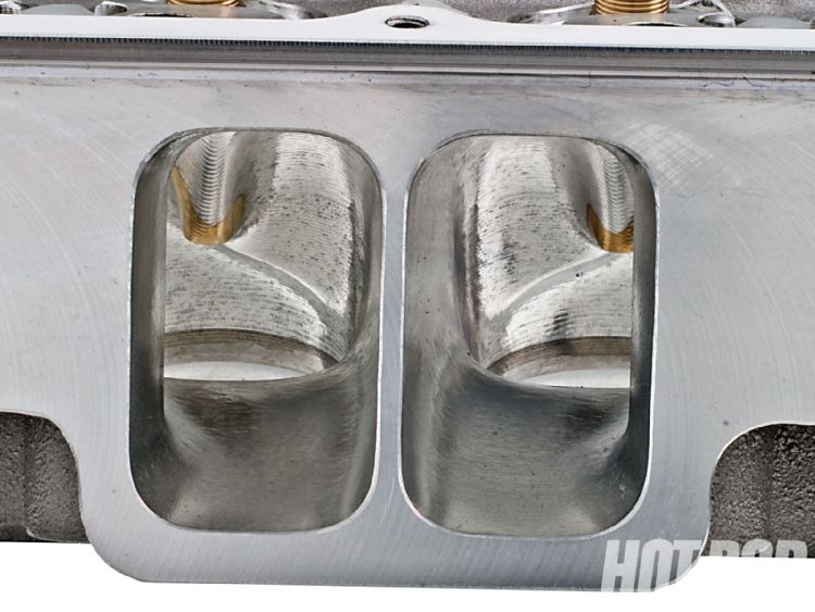
BOWL PORT/BOWL BLEND/POCKET PORT (They all mean the same thing.)
This is the most important part of porting a head. This place if done correctly will result in good CFM gains. At the same time one wrong move here will result in a head that flows less than a stock. You cant make any mistakes here. Our flowbench testing has shown us what to touch and what not too. Most porters blend the short sides as common practice not realizing some of those edges are what makes the head flow well as we discovered on an Honda S2000 head. Bumps and sharp edges are not bad all the time. Once again flowbench testing helped us determin this.
CUT SEATS/GRIND SEATS
ALANIZ uses special carbide cutting tools/machines to cut the valve seats. Grinding procedures are also performed because we have found carbide tooling doesnt always cut perfectly round on hardened seats. Carbide cutters have a tendency to jump when it comes in contact with hard spots. A simple way of checking a carbide cut is place the valve in the seat with no spring and look through the port while holding it with one finger. Look through the port. If you see light you know its not perfectly round. Thats were the stone comes in. We here at ALANIZ always come back and KISS the seats with a finishing stone. The stone grinds away the hard spot leaving you with a perfect seal. On extreme applications such as supercharged, turbo, NOS engines there is no room for errors. Any gaps in the VALVE to SEAT contact area will result in a burned valve. ALANIZ pays special attention to these areas resulting in leak proof valve jobs. Knowing what angles to use is very important here. Honda heads are very sensitive to valve jobs. One wrong angle will reduce flow dramatically. When valve seatwork is performed, it's important to measure the installed height with an indicator. Setting all valves to the same height ensures consistency of combustion-chamber volume and helps equalize spring pressure.
FLOW BENCH
A flowbench is machine, which tells you how much air can flow through a port, manifold or throttle body. This machine is the most important tool when it comes to porting. Without one you will never be able to achieve the highest possible CFM gains. All of our porting and valve job experience comes from utilizing a Superflow flowbench. It guides us in the rite direction by telling us if flow is gained or lost while keeping good port velocity. All Competition heads are flowed to make sure they perform flawlessly. ALANIZ heads are flowed @ 28" of water.
GASKET MATCH/PORT MATCH
All this means is equalizing diameters of adjoining runners. E.g. manifold to head. Most modern multi valve head from the factory come almost perfect in respects to the intake side. A light massage is all it needs.
LAP VALVES AND SEATS
A very light abrasive compound is use to lightly sand the valves into place. When ALANIZ performs its valve jobs it uses this procedure to check margin thickness and quality. We do not use it to cure an out of round, off center or just plain bad valve job as others shops may do. We vacuum check our work rights after the Valve job is performed then lap the valves in.
MILLING
This is a machining process that removes metal from the head-gasket-surface area. It purpose is to remove imperfections from the head surface. It is also used for increasing the compression ratio of an engine. ALANIZ checks both valve cover surface as well as the head gasket surface to make sure the head is straight before milling. Milling should never done if the head is bent. STRAIGHTEN IT FIRST then mill it otherwise uneven cam journal wear will occur. In a worst-case scenario the cam journal and cam will simply destroy it self.
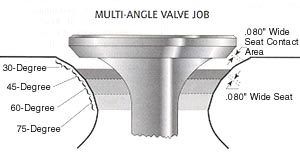
MULTI-ANGLE VALVE JOB
A multi angle valve job is the cutting or grinding of 2 or more angles on the seat and valve. The purpose of a multi angle valve job is to improve airflow. By now you have probably heard of 5 angle and radius valve jobs. The truth, this is more applicable in the American iron heads. There just isnt enough material in the small diameter seats or valves to see any real noticeable differences on a flow bench. A .5% gain maybe seen on a flowbench but the flowbench has a plus or minus error factor that has to be eliminated before a true flow figure can be attained. Older American iron heads may benefit from a five angle or radius valve job but only because the head is so bad to begin with. The Honda head is diffrent. Our flowbench testing has proven time after time that the correct angles and angle widths is what is important. More CFM gains have been made through this procedure than applying 5 angles or radiuses.
POLISHING
Polishing a port or combustion chamber does not alter the shape or size, but instead smoothes the surface to increase flow and reduce the build up of combustion deposits. On the intake side of an ALANIZ port job we give it a rough polish. Why? Your fuel injectors work in milliseconds. Ever wonder in 8 milliseconds how many degrees your crankshaft has turned if it is operating at 9000rpm? Your crankshaft has turned approx. 450deg. That means your injector has to start firing fuel way before the intake valve has even opened. Most of the fuel does vaporize as it hits the back of the valve but the rest of the fuel that doesnt vaporize ends up on the walls, short sides and around the valve area until the valve finally opens and draws in the air fuel mixture. Keeping the walls rough in theory helps break up the fuel particles before it enters the combustion chamber. Atomized fuel burn better resulting in more horsepower and better fuel economy.
PORTING
Porting reshapes or enlarges by cutting, grinding, machining or in some cases adding material.
SHORT SIDE OR TURN
This refers to the shorter, tighter side of a turn in a port.
TOP CUT
The valve seat angle nearest the combustion chamber.
UNSHROUD THE VALVES
Removal of chamber material closest to the valve from the valve seat to the head surface. This is one
area that if you get correct, you will see major horsepower increases.
polishing the combustion chambers and smoothing contours tends to reduce detonation and improve power
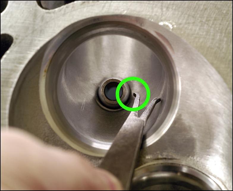
VALVE GUIDES
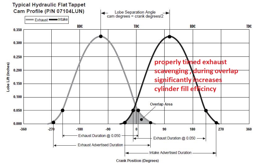
A thick sleeve usually cast iron or bronze which helps guide the up and down motion of the valve. Guides are very important because if worn out they can cause valve instability and consume oil by letting it seep in to the combustion chamber. Running some hot cams? Loose guides will also cause problems during the overlap period when the intake and exhaust valves are closest to each other causing the probability of valve to valve contact.
VALVE SEALS
A valve seal is a seal, which helps oil not seep into the combustion chamber. It is positioned on top of the valve guide.
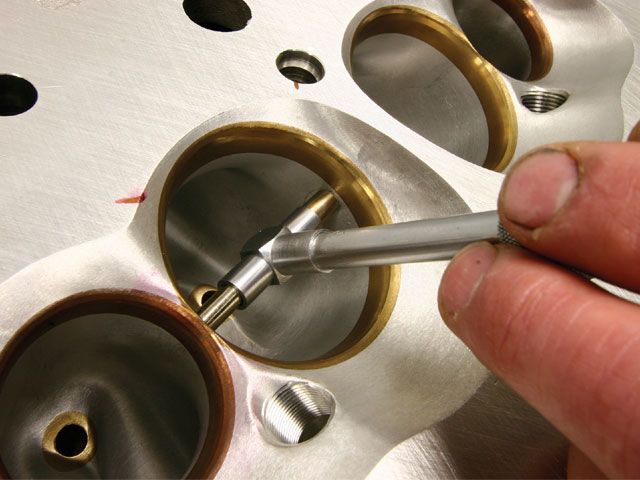
obviously dealing with a machine shop know to do quality and consistent high quality, 3 angle valve jobs is the first step in this process,
Yes ,Ive generally found you will need to disassemble and check run-out yourself and yeah,
that requires you purchase a few tools to do it accurately.
you can generally verify valve seat seal with simply pouring alcohol into the intake or exhaust ports with what ever port your testing vertical and watching for solvent or alcohol seepage in the combustion chamber ,
alcohol will seep past a marginal valve seat seal contact far faster than water will due to its lack of surface tension, so its a better test fluid. hand lapping the valve seats tends to help.
hand lapping valve seats can be done reasonably easily and greatly increases valve seat seal.
https://www.enginebuildermag.com/2013/10/cautioning-on-valve-seat-concentricity/
http://garage.grumpysperformance.co...olishing-combustion-chambers.2630/#post-50247
http://garage.grumpysperformance.co...gree-valve-seats-tpi-motors.14662/#post-78724
http://garage.grumpysperformance.com/index.php?threads/how-to-lap-valve-seats.1159/#post-2362
http://garage.grumpysperformance.co...video-with-info-worth-watching-through.15999/
Ive suggested your average skilled mechanic or hot rod enthusiast,
spend time in doing research in, and then if they choose too,
cleaning up the bowl area under the valves , of casting flash,
and valve seat machining ridges,getting a multi angle valve job,
narrowing the valve guides port matching the heads/intake manifold,
and polishing and ccing the combustion chambers,
you should not be significantly altering or enlarging the ports or runners,
multi angle valve jobs should be left too the pros with the correct machinery,
and precise measuring equipment,
but a home shop can certainly lap valves and clean up the port and bowl area ,
and port match, and blend , polish and cc combustion chambers, etc.
reading links and sub-links generally helps
http://garage.grumpysperformance.co...ng-combustion-chambers.2630/page-3#post-77963
http://garage.grumpysperformance.com/index.php?threads/ccing-my-heads.14187/#post-71989
http://garage.grumpysperformance.co...needs-clean-up-equalization.12474/#post-62647
http://garage.grumpysperformance.co...r-piston-dome-or-port-volume.2077/#post-61068
http://garage.grumpysperformance.co...ing-tools-abrasives-sources.10683/#post-46209
http://garage.grumpysperformance.co...lve-seat-angles-and-air-flow.8460/#post-29682
http://garage.grumpysperformance.com/index.php?threads/multi-angle-valve-job-related.3143/#post-8387
http://garage.grumpysperformance.com/index.php?threads/valve-train-clearances-and-problems.528/
http://garage.grumpysperformance.co...e-springs-and-setting-up-the-valve-train.181/
http://garage.grumpysperformance.com/index.php?threads/rocker-push-rod-wear-issues.9815/
air flow tends to develop turbulence, that lowers the flow volume if its forced to change direction over a sharp machined edge, if the change exceeds about 15 degrees, that's why most valve seat areas are multiples of no more than 15 degree changes in angle.
back cutting the valve tends to smooth flow thru the curtain area at low lifts and its not unusually to pick up several horsepower doing so
as a valve wears and the valve seats wear the seal tends to slowly degrade, but because both the valve edge and the valve seat angles form concentric cones the valve tends to seat slightly deeper and stays sealed to compensate for minor wear.
naturally the port and bowl area configuration under the valve seat and the intake and exhaust port size , length, cross section and pressure and angle effect the flow rates thru the valves.
read this related thread and sub linked info
http://garage.grumpysperformance.com/index.php?threads/valve-seat-angles-and-air-flow.8460/
Cheap Good Cylinder Heads
Where do you find good and cheap cylinder heads? A set of these for $280 + valves + springs, reuse old rocker arms = $400 https://www.ebay.com/itm/393005918509 https://www.ebay.com/itm/322892146731 https://garage.grumpysperformance.com/index.php?threads/sellecting-cylinder-heads.796/page-2 Buy...
garage.grumpysperformance.com
How Valves Seal
Watch this video by Eric Weingartner, I learned alot, I think you will to ! .
garage.grumpysperformance.com
http://garage.grumpysperformance.com/index.php?threads/valve-seat-runout.15104/#post-86003
http://garage.grumpysperformance.co...video-with-info-worth-watching-through.15999/
http://garage.grumpysperformance.co...alves-and-polishing-combustion-chambers.2630/
its been my experience that a properly done valve job with 3-5 angles and its the port throat and valve guide area under the valve,
[
that is a huge factor in its potential flow, but remember the header scavenging and compression and cam timing all effect the potential results, while the article may promote the 50 Deg valve seat angle a change in cam timing port shape or exhaust scavenging or rocker ratio, various porting tech, piston too combustion chamber mods, heat reflective coating, merge collectors , would have a more noticeable effect on the engines power curve in my opinion.
theres a reason the early SBC 23 degree heads with similar valve size to the later 18 degree heads can,t keep up, and its not the valve seat angles, theres a reason the later vortec heads with similar port volume and valve size to the mildly ported corvette fuelie heads out flow those early heads that were designed in the 1960s , and its not the valve seat angles!
and the biggest reason the 50 degree valve seat angle is not commonly used is long term durability, valves wear and seats wear and as the valve sinks deeper into the heads combustion chamber flow is reduced , now on a race engine that will be dis-assembled every season that may not be a huge issue, but if you expect to get 50K-100K miles its something you'll want to think through.
blending the valve seat into the port throat with a 3-5 degree multi angle valve job, and porting the bowl area and valve guides,will have far more effect on power than a couple degree change in valve seat angle
read this related thread and sub linked info
http://garage.grumpysperformance.com/index.php?threads/valve-seat-angles-and-air-flow.8460/
http://garage.grumpysperformance.co...alves-and-polishing-combustion-chambers.2630/
Here is an excerpt from an AERA TB,,
===================
Exhaust Valve Guide Caution On
1965-98 GM Big Block Engines
These engines' valve guides were not intended as a replacement item from GM.
The guides were located into the head castings after the head was cast and
the exhaust guide is "water cooled".
The water-cooled guide also has two different size press fit diameters. Adding additional confusion to the matter, they also switched the location of the larger diameter sometime in 1985.
To determine which outside diameter guide you have and which direction to
remove an exhaust valve guide, the following procedure is suggested:
Drive the guide no more than .250" (6.35 mm) toward the valve spring side of
the head and stop. Then, measure the newly exposed area of the guide
OD next to the spring pad.
If the measurement is .620" it is the first style guide. To remove this
style guide, continue driving it toward the valve spring side of the head.
If the measurement is .616" , it is the second style guide. To remove
this style guide, you must drive it the opposite direction toward the combustion
chamber side of the head.
read the links
http://www.engr.colostate.edu/~allan/fl ... age4f.html
viewtopic.php?f=52&t=333&p=8319&hilit=flow+bench#p8319
viewtopic.php?f=38&t=1099&p=2215&hilit=+flow+bench#p2215
http://www.altsale.com/frm.htm
viewtopic.php?f=50&t=3422&p=9066#p9066
http://www.aera.org/ep/downloads/ep1/EP012008_34-40.pdf
http://garage.grumpysperformance.com/index.php?threads/how-to-lap-valve-seats.1159/#post-2362
viewtopic.php?f=52&t=8596&p=30222#p30222
http://en.wikipedia.org/wiki/Air_flow_bench
viewtopic.php?f=27&t=408&p=688&hilit=+flow+bench#p688
http://www.carcraft.com/techarticles/11 ... to_04.html
http://www.alexsparts.com/
a basic but effective valve job with blended port bowl area clean -up helps flow rates
on a performance application a 5 angle valve job and back cutting the valves can add significantly to the port flow but its usually some what wasted effort on any engine with less than 240 degrees of cam duration at .050 lift, and less than 10:1 compression or one thats not designed to operate at over 6000 rpm, and generally not done
valves can be back cut to smooth low lift flow as well as ports
a carefully contoured and smoothed port, and bowl area under the valve tends to flow better
http://www.enginebuildermag.com/Article ... _jobs.aspx
a carefully blended and unshrouded combustion chamber also helps increase flow
port and bowl configuration can drastically effect flow thru the valve
http://www.eddiesvalvegrinding.com/valve-grinding.htm
http://books.google.com/books?id=AatRNA ... ob&f=false
https://goodson.com/collections/cylinder-head-rebuilding-tools
http://www.cylinderheadsupply.com/kl8540.html
HEAD TERMINOLOGY
Cylinder Head Design and Terms
By Joe Alaniz (Air Flow Technician)
ALANIZ has taken the time to hopefully educate the sports car enthusiast about certain words and procedures. So lets get started.
BACK CUT VALVE
This describes an additional angle added to the valve head to improve flow. Be aware different angles give different flow results at certain valve lifts.
BOTTOM CUT (throat cut)
The bottom cut is just as it sounds, the cut furthest into the valve-throat area. This cut opens the throat diameter to mate up with the main seating angle. On Honda B16/GSR heads, this angle has the greatest affect on mid to high valve lifts.
BOWL PORT/BOWL BLEND/POCKET PORT (They all mean the same thing.)
This is the most important part of porting a head. This place if done correctly will result in good CFM gains. At the same time one wrong move here will result in a head that flows less than a stock. You cant make any mistakes here. Our flowbench testing has shown us what to touch and what not too. Most porters blend the short sides as common practice not realizing some of those edges are what makes the head flow well as we discovered on an Honda S2000 head. Bumps and sharp edges are not bad all the time. Once again flowbench testing helped us determin this.
CUT SEATS/GRIND SEATS
ALANIZ uses special carbide cutting tools/machines to cut the valve seats. Grinding procedures are also performed because we have found carbide tooling doesnt always cut perfectly round on hardened seats. Carbide cutters have a tendency to jump when it comes in contact with hard spots. A simple way of checking a carbide cut is place the valve in the seat with no spring and look through the port while holding it with one finger. Look through the port. If you see light you know its not perfectly round. Thats were the stone comes in. We here at ALANIZ always come back and KISS the seats with a finishing stone. The stone grinds away the hard spot leaving you with a perfect seal. On extreme applications such as supercharged, turbo, NOS engines there is no room for errors. Any gaps in the VALVE to SEAT contact area will result in a burned valve. ALANIZ pays special attention to these areas resulting in leak proof valve jobs. Knowing what angles to use is very important here. Honda heads are very sensitive to valve jobs. One wrong angle will reduce flow dramatically. When valve seatwork is performed, it's important to measure the installed height with an indicator. Setting all valves to the same height ensures consistency of combustion-chamber volume and helps equalize spring pressure.
FLOW BENCH
A flowbench is machine, which tells you how much air can flow through a port, manifold or throttle body. This machine is the most important tool when it comes to porting. Without one you will never be able to achieve the highest possible CFM gains. All of our porting and valve job experience comes from utilizing a Superflow flowbench. It guides us in the rite direction by telling us if flow is gained or lost while keeping good port velocity. All Competition heads are flowed to make sure they perform flawlessly. ALANIZ heads are flowed @ 28" of water.
GASKET MATCH/PORT MATCH
All this means is equalizing diameters of adjoining runners. E.g. manifold to head. Most modern multi valve head from the factory come almost perfect in respects to the intake side. A light massage is all it needs.
LAP VALVES AND SEATS
A very light abrasive compound is use to lightly sand the valves into place. When ALANIZ performs its valve jobs it uses this procedure to check margin thickness and quality. We do not use it to cure an out of round, off center or just plain bad valve job as others shops may do. We vacuum check our work rights after the Valve job is performed then lap the valves in.
MILLING
This is a machining process that removes metal from the head-gasket-surface area. It purpose is to remove imperfections from the head surface. It is also used for increasing the compression ratio of an engine. ALANIZ checks both valve cover surface as well as the head gasket surface to make sure the head is straight before milling. Milling should never done if the head is bent. STRAIGHTEN IT FIRST then mill it otherwise uneven cam journal wear will occur. In a worst-case scenario the cam journal and cam will simply destroy it self.
MULTI-ANGLE VALVE JOB
A multi angle valve job is the cutting or grinding of 2 or more angles on the seat and valve. The purpose of a multi angle valve job is to improve airflow. By now you have probably heard of 5 angle and radius valve jobs. The truth, this is more applicable in the American iron heads. There just isnt enough material in the small diameter seats or valves to see any real noticeable differences on a flow bench. A .5% gain maybe seen on a flowbench but the flowbench has a plus or minus error factor that has to be eliminated before a true flow figure can be attained. Older American iron heads may benefit from a five angle or radius valve job but only because the head is so bad to begin with. The Honda head is diffrent. Our flowbench testing has proven time after time that the correct angles and angle widths is what is important. More CFM gains have been made through this procedure than applying 5 angles or radiuses.
POLISHING
Polishing a port or combustion chamber does not alter the shape or size, but instead smoothes the surface to increase flow and reduce the build up of combustion deposits. On the intake side of an ALANIZ port job we give it a rough polish. Why? Your fuel injectors work in milliseconds. Ever wonder in 8 milliseconds how many degrees your crankshaft has turned if it is operating at 9000rpm? Your crankshaft has turned approx. 450deg. That means your injector has to start firing fuel way before the intake valve has even opened. Most of the fuel does vaporize as it hits the back of the valve but the rest of the fuel that doesnt vaporize ends up on the walls, short sides and around the valve area until the valve finally opens and draws in the air fuel mixture. Keeping the walls rough in theory helps break up the fuel particles before it enters the combustion chamber. Atomized fuel burn better resulting in more horsepower and better fuel economy.
PORTING
Porting reshapes or enlarges by cutting, grinding, machining or in some cases adding material.
SHORT SIDE OR TURN
This refers to the shorter, tighter side of a turn in a port.
TOP CUT
The valve seat angle nearest the combustion chamber.
UNSHROUD THE VALVES
Removal of chamber material closest to the valve from the valve seat to the head surface. This is one
area that if you get correct, you will see major horsepower increases.
polishing the combustion chambers and smoothing contours tends to reduce detonation and improve power
VALVE GUIDES
A thick sleeve usually cast iron or bronze which helps guide the up and down motion of the valve. Guides are very important because if worn out they can cause valve instability and consume oil by letting it seep in to the combustion chamber. Running some hot cams? Loose guides will also cause problems during the overlap period when the intake and exhaust valves are closest to each other causing the probability of valve to valve contact.
VALVE SEALS
A valve seal is a seal, which helps oil not seep into the combustion chamber. It is positioned on top of the valve guide.
obviously dealing with a machine shop know to do quality and consistent high quality, 3 angle valve jobs is the first step in this process,
Yes ,Ive generally found you will need to disassemble and check run-out yourself and yeah,
that requires you purchase a few tools to do it accurately.
you can generally verify valve seat seal with simply pouring alcohol into the intake or exhaust ports with what ever port your testing vertical and watching for solvent or alcohol seepage in the combustion chamber ,
alcohol will seep past a marginal valve seat seal contact far faster than water will due to its lack of surface tension, so its a better test fluid. hand lapping the valve seats tends to help.
hand lapping valve seats can be done reasonably easily and greatly increases valve seat seal.
https://www.enginebuildermag.com/2013/10/cautioning-on-valve-seat-concentricity/
http://garage.grumpysperformance.co...olishing-combustion-chambers.2630/#post-50247
http://garage.grumpysperformance.co...gree-valve-seats-tpi-motors.14662/#post-78724
http://garage.grumpysperformance.com/index.php?threads/how-to-lap-valve-seats.1159/#post-2362
http://garage.grumpysperformance.co...video-with-info-worth-watching-through.15999/
Ive suggested your average skilled mechanic or hot rod enthusiast,
spend time in doing research in, and then if they choose too,
cleaning up the bowl area under the valves , of casting flash,
and valve seat machining ridges,getting a multi angle valve job,
narrowing the valve guides port matching the heads/intake manifold,
and polishing and ccing the combustion chambers,
you should not be significantly altering or enlarging the ports or runners,
multi angle valve jobs should be left too the pros with the correct machinery,
and precise measuring equipment,
but a home shop can certainly lap valves and clean up the port and bowl area ,
and port match, and blend , polish and cc combustion chambers, etc.
reading links and sub-links generally helps
http://garage.grumpysperformance.co...ng-combustion-chambers.2630/page-3#post-77963
http://garage.grumpysperformance.com/index.php?threads/ccing-my-heads.14187/#post-71989
http://garage.grumpysperformance.co...needs-clean-up-equalization.12474/#post-62647
http://garage.grumpysperformance.co...r-piston-dome-or-port-volume.2077/#post-61068
http://garage.grumpysperformance.co...ing-tools-abrasives-sources.10683/#post-46209
http://garage.grumpysperformance.co...lve-seat-angles-and-air-flow.8460/#post-29682
http://garage.grumpysperformance.com/index.php?threads/multi-angle-valve-job-related.3143/#post-8387
http://garage.grumpysperformance.com/index.php?threads/valve-train-clearances-and-problems.528/
http://garage.grumpysperformance.co...e-springs-and-setting-up-the-valve-train.181/
http://garage.grumpysperformance.com/index.php?threads/rocker-push-rod-wear-issues.9815/
Last edited by a moderator:


