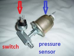
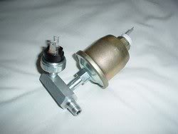
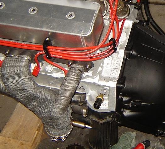
Grumpy my 1985 corvette would not start, I eventually traced it eventually to a defective oil pressure sensor and switch, near the base of the HEI distributor,
I only found your thread giving the OHMS levels to test the sensor,
only after I found the problem by swapping out parts,
that were suggested on several web sites,
I would have saved a lot of wasted time and effort if I had started reading rather than buying and replacing parts in almost a random pattern.
based solely on other peoples guess work.
yes thats a rather common sensor to fail in a 20 plus year old corvette.
https://www.howacarworks.com/accessories/how-an-oil-pressure-guage-works
the gauge circuit works by reading OHMS resistance.
Basically a bad sender that is open would make the gauge peg.
When there is no oil pressure it is grounded.
Which is why unplugging it may have made no difference
some early c4 vettes have the gauge and oil pressure switch on an adapter near the distributor base into the block,
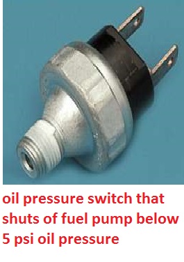
low oil pressure or a defective oil pressure sensor will cut off your ignition on many cars as a safety feature, the typical sensor and switch is located near the distributor base on the rear of the block.
most oil pressure and fuel pressure gauges now are electric and use a sensor and wires to transmit the sensor data to the gauge , the last thing you want is a broken line allowing fuel or oil under pressure to pass through the fire wall, in fact most racing rules forbid that oilder manual type of gauge use.
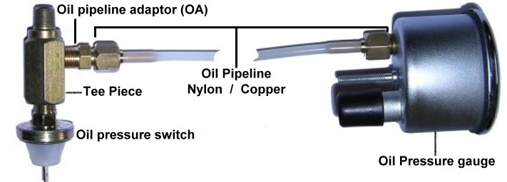
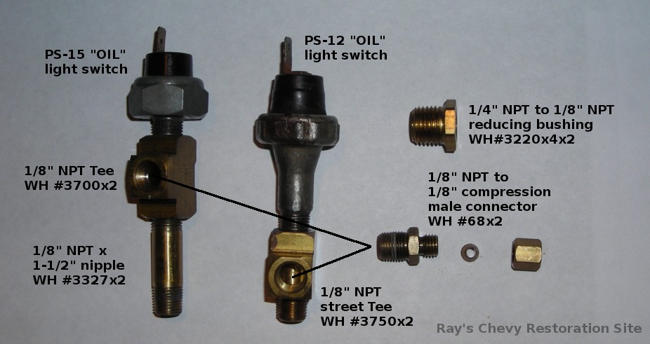
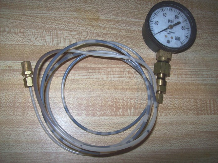
Mechanical oil gauge
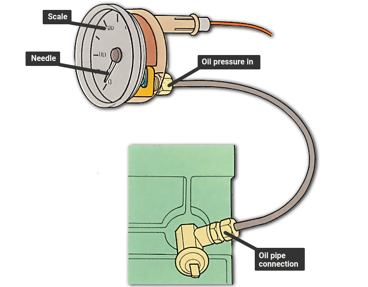
Oil is fed to the gauge by a pipe with screwed olive connections. Union pieces allow several sensors to be connected to one tapping — copper washers seal joints.
Oil is sent to the gauge from the tapping in the engine's oilway by a small-bore (3mm) pipe, usually copper or plastic. The pipe is routed away from anything that could damage it, because if the pipe is punctured the engine's oil would leak out.
The pipe enters the passenger compartment via a grommetted hole in the bulkhead, and joins the stub on the back of the gauge via a knurled connector.
The gauge contains a flexible coiled tube called a bulb, the open end of which is rigidly mounted to the gauge's outer casing. The other end of the bulb is closed and connected by a lightweight linkage to the bottom end of the needle, which is itself mounted on a pivot.
Oil is fed into the bulb from the supply pipe at very nearly the same pressure as it left the engine. The bulb tries to straighten under the pressure and in doing so moves the needle around the calibrated gauge scale . The greater the pressure, the more the needle moves.
Electric gauges
Electric sensor units
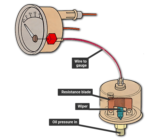
Sensor units for electric gauges work by sliding a wiper up a curved blade of known resistance. The wiper is moved by a diaphragm which keeps the sender oil-tight.
If your manual oil pressure gauge is stuck in one position ,check to verify the indicator needle is not bent, and you might also want to try spraying some carb cleaner solvent into the tube feeding oil pressure into the gauge then repeatedly applying high air pressure from your compressor,intermittently, and repeatedly, and removing the air pressure to cycle the solvent fluid in the tube to allow it to work its way up too the gauge to dissolve any sludge, in many case the tube has a fitting on the back of the gauge that can be temporarily disconnected so you can use solvent and air pressure to check the tube is clear and get easy access too the gauge internals.
obviously if the tubes blocked it needs to be cleared or replaced, if the gauge is defective, its probably cheaper to replace than repair
the gauge circuit works by reading OHMS resistance.
Basically a bad sender that is open would make the gauge peg.
When there is no oil pressure it is grounded.
Which is why unplugging it may have made no difference
some early c4 vettes have the gauge and oil pressure switch on an adapter near the distributor base into the block, your code scanner won,t work on the OBDI
pre 1996 engines as the scanners are generally OBDII 1996 and newer,
so its going to take a bit more testing to locate, but if you tend to get the engine to briefly start than get no spark thats a clue, theres links below that may help/
but with test clips you can test the ohms reading on the sensor and with a multi meter you can also test the voltage and of course test for ignition spark, and of course always verify oil pressure with a second gauge if thats suspected of not reaching 5-6 psi within seconds of trying to start the engine, as that oil pressure sensor shuts off the fuel pump in the cars tank if you have no oil pressure
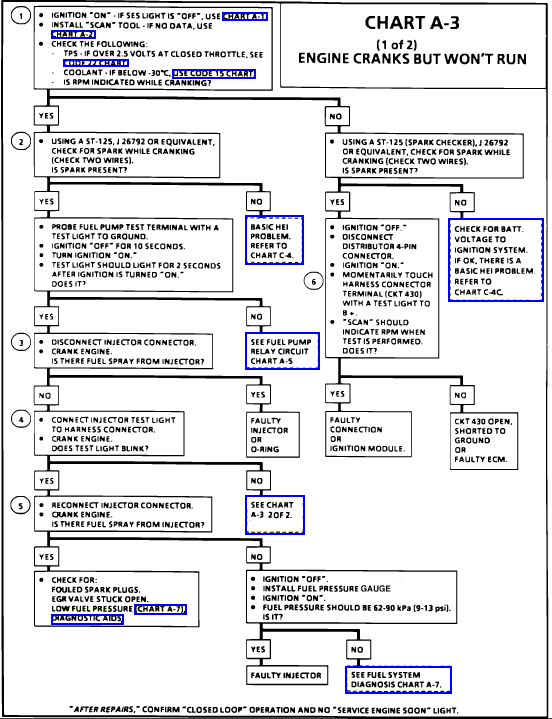
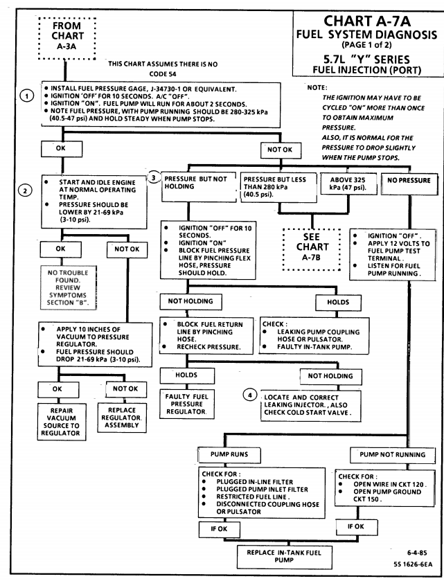
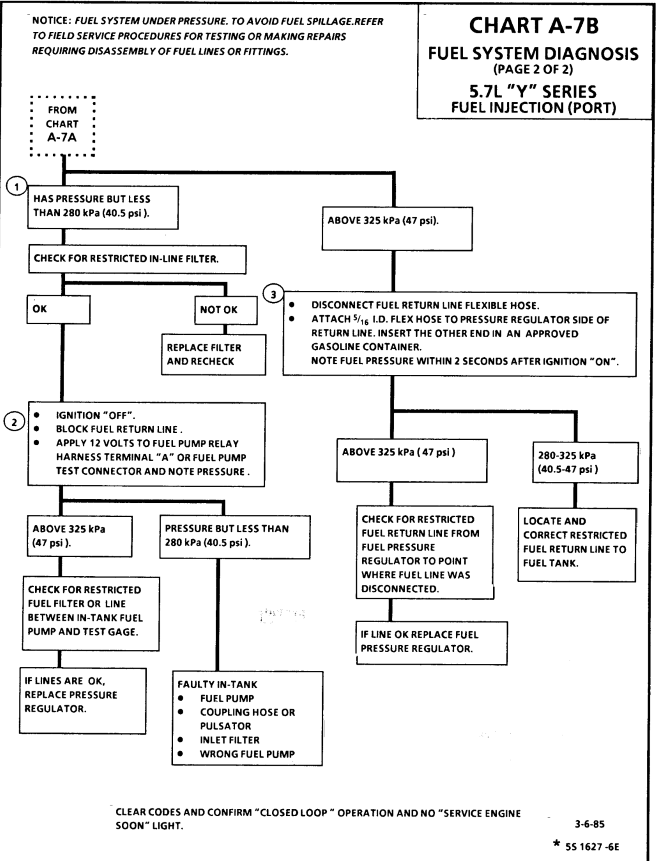
L98/ TPI Engine Start Sequence
When you start an L-98 engine Corvette, a series of events take place that causes the engine to run. Knowing the sequence will help you troubleshoot no start conditions.
Fuel Rail Pressurization:
When you first turn the key to the “on” position, the fuel pump will run for 2 seconds pressurizing the fuel rails. There is a Shraeder valve on the passenger side fuel rail near the rear of the engine and if you measure the pressure there after the pump runs, you should see between 40-42 pounds of pressure. The reading will go to 38-40 pounds nominal once the engine is running.
Initial Crank Action:
If you then rotate the key to the start position (assuming the anti-theft system has not disabled the starter), the engine will rotate.
Once the oil pressure has reached 4 PSI, the oil pressure switch will close allowing the fuel pump to run. (Note that you should have a black oil pressure switch/sender. It is mounted behind the distributor on the driver’s side and if it is not black, it is suspect due to a run of bad units that stayed in the GM parts pipeline for some time).
The distributor will send a string of pulses to the ECM (Engine Control Module) in response to the engine being rotated by the starter. These pulses continue as long as the engine turns (both starting and running) and if they are not present, the engine will not run.
ECM Reaction:
If the ECM sees oil pressure greater than 4 PSI and the reference pulses from the distributor, it will energize the injector drivers which will begin pulsing the injectors on for 4 ms (milliseconds) periods. (In the L98, all injectors on one side of the engine fire at the same time followed by all injectors on the other side firing at the same time. On the LT-1, the injectors are fired individually at the appropriate time).
The ECM will also pull in the fuel pump relay in effect paralleling it electrically with the oil pressure switch. (If the fuel pump relay fails, you can still normally get the car to start and run unless you can’t make at least 4 PSI oil pressure. This is a “limp home mode” feature put in place to allow for a fuel pump relay failure).
The ECM also monitors the TPS (Throttle Position Sensor mounted on the throttle body assembly) and wants to see .54 volts at this time. If it sees appreciably more than 0.54 volts, it will assume the engine is flooded and the driver has pressed the accelerator to the floor to clear the flooded condition and restrict the fuel flow as a result. (.54 volts during start and at idle from the TPS is very important to both starting and run performance.)
Assuming the ignition module is good (meaning there is a spark of sufficient intensity to ignite the fuel), the engine will “catch”.
Engine "Catches":
When the engine catches, the MAF (Mass Air Flow sensor mounted just ahead of the throttle body) sends a signal to the ECM advising that air is flowing and also just how much air is being pulled through to the intake manifold. The ECM takes note of the amount of air being consumed and adjusts the injector pulse width to around 2.2 ms nominally so as to attain a proper air/fuel mixture to insure combustion. (This is how the 1985 through 1989 L-98 works. For information on the 1990 and 1991 L-98 variant, see the Note below).
The engine should show an initial idle speed of around 900-1100 RPM and then slowly diminish to 600-700 RPM unless the air conditioner is on in which case it will run at around 800 RPM.
If this does not happen, the Idle Air Mixture valve (located on the throttle body) may be misadjusted. Alternatively, there may be a leak in the intake manifold or another vacuum leak may be present. Listen for hissing sounds---there should be none.
ECM Mode:
The engine will now be in Open Loop mode meaning that the ECM is controlling the air/fuel mixture by referencing values stored in memory.
Once the Oxygen sensor (mounted on the exhaust pipe) reaches operating temperature of several hundred degrees, the Manifold Air Temperature (MAT) sensor shows an intake air temperature of more than 140 degrees and the Engine Coolant Temperature (ECT) has reached 160 degrees, the computer will switch to closed loop mode meaning the Oxygen sensor’s output is examined along with the MAT and ECT outputs and the ECM adjusts the injector pulse widths (more “on time” or less “on time”) to constantly strive for a 14.7:1 air/fuel mixture which is the best mixture to hold down pollution.
Note that prolonged idling can force the computer back into open loop mode.
Note: In 1990, the MAF was eliminated from the engine in favor of a speed/density system. This system uses a sensor called the MAP sensor which measures the Manifold Absolute Pressure (hence the name MAP) and compares it with the atmospheric pressure outside the intake manifold. This information, coupled with the Manifold Air Temperature, Engine Coolant Temperature and Engine RPM is used by the ECM to determine the amount of air entering the cylinders. It is a different way of reaching the desired 14.7:1 air-fuel mixture ratio but functionally is like the MAF system in that the ECM uses the feedback to control the "on time" for the injectors.
Corvette used this approach in the 1990 and 1991 L-98 engines and in the 1992 and 1993 LT-1 engines. With the 1994 model C4, they went back to the MAF system. Note that MAF based systems are far more accurate since they measure air flow directly whereas the MAP system infers air flow indirectly. A multitude of things can throw the calculation off and Corvette returned to the MAF system beginning with the 1994 C4 (with a MAP backup). From a troubleshooting standpoint, the MAP operation comes into the sequence the same place that the MAF does.
Summary:
If you have a no start condition or if the L-98 starts and then dies, check the above items in sequence to see if all the events are occurring as required.
A Scan Tool makes this job much easier and is a highly recommended troubleshooting aid for these sorts of problems.
youll find a hour or so reading thru the links and sub links, on this site in the threads, will provide a great wealth of related info and incite into related factors, or the function or testing of sensors, that you may not currently be thinking about, or things that you might not think that are related to your issue that PROBABLY ARE
without testing your simply guessing READ THE LINKS AND SUB LINKS AND THINK LOGICALLY... AND ASK
QUESTIONS
http://garage.grumpysperformance.com/index.php?threads/c4-c5-corvette-trouble-codes.2697/
http://garage.grumpysperformance.co...start-right-back-up-and-run.10739/#post-46893
http://garage.grumpysperformance.com/index.php?threads/tpi-fuel-pressure-issue.10385/#post-42943
http://garage.grumpysperformance.co...ouble-shooting-rebuilding-hei-ignitions.2798/
http://garage.grumpysperformance.co...years-now-i-want-to-sell-it.13790/#post-70731
http://garage.grumpysperformance.co...ard-starting-tpi-crossfire-or-lt1-vette.1401/
http://garage.grumpysperformance.co...lay-switch-locations-and-info.728/#post-54562
http://garage.grumpysperformance.com/index.php?threads/adjusting-your-tps-and-iac.168/
http://garage.grumpysperformance.co...-system-trouble-shooting-flow-chart-info.596/
http://garage.grumpysperformance.co...-system-vats-making-you-crazy.520/#post-45062
http://garage.grumpysperformance.co...s-cause-a-bad-idle-in-drive.14203/#post-72114
http://garage.grumpysperformance.co...questions-can-be-found-here.12892/#post-67808

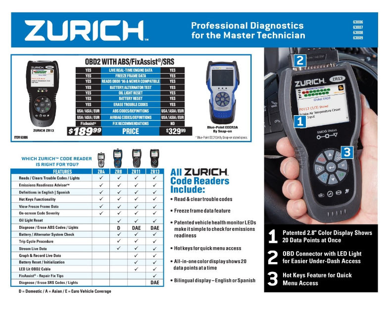
if you purchase a ZR13 auto code scanner, from HF,
you need this info
DOWN-LOAD AND PRINT IT OUT!
https://manuals.harborfreight.com/manuals/63000-63999/Q63806.pdf
https://manuals.harborfreight.com/manuals/63000-63999/63806.pdf

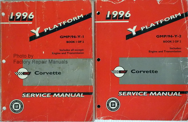
your working at a huge dis-advantage if you don,t have a factory shop manual for your specific year car, and basic tools like a multi-meter, and vacuum /pressure gauge
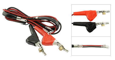
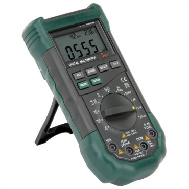
MULTI METER
Measured Value
Engine Coolant Temperature Sensor. 185 Ohms @ 210F, 3400 Ohms @ 68F, 7,500 Ohms @ 39 F.
Engine Oil Temperature Sensor. 185 Ohms @ 210 F, 3400 Ohms @ 68 F, 7,500 Ohms @39 F.
Oil Pressure Sender/Switch. 1 Ohms @ 0 PSI, 43 Ohms @ 30 PSI, 86 Ohms @ 60 PSI.
Fuel Quantity Sender. 0 Ohms @ Empty, 45 Ohms @ 1/2 Full, 90 Ohms @ Full.
MAT (Manifold Absolute Temperature Sensor). 185 Ohms @ 210 F, 3400 Ohms @ 70 F, 15,000 Ohms @ 40 F.
Outside Temperature Sensor. 4400 Ohms @ 60 F, 2200 Ohms @ 85 F.
In Car Temp Temperature Sensor. 4400 Ohms @ 60 F, 2200 Ohms @ 85 F.
MAF (Mass Air Flow) Sensor. .4 Volts @ idle, 5 Volts @ Full Throttle.
Oxygen (O2) Sensor. .1 Volt Lean Mixture, .9 Volt Rich Mixture.
TPS (Throttle Position Sensor). .54 Volts Idle, ~ 5 Volts Full Throttle.
Sensor Locations
Sensor
Location
Engine Coolant Temperature Sensor. Front of engine, below Throttle Body.
Engine Oil Temperature Sensor. Left rear of engine, just above the oil filter.
Oil Pressure Sender/Switch. Top, left hand rear of engine.
Fuel Quantity Sender. Top of fuel tank, beneath filler pipe escutcheon panel.
MAT (Manifold Absolute Temperature Sensor). Underside of manifold air plenum at rear.
Outside Temperature Sensor. Right side of engine, top right corner of radiator.
In Car Temp Temperature Sensor. Coupe: above left seat near interior courtesy light, Convertible: center of cargo compartment lid.
MAF (Mass Air Flow) Sensor. Front of engine ahead of throttle body.
Oxygen (O2) Sensor. Left side of engine, in exhaust pipe.
TPS (Throttle Position Sensor). Right side of throttle body at the front.
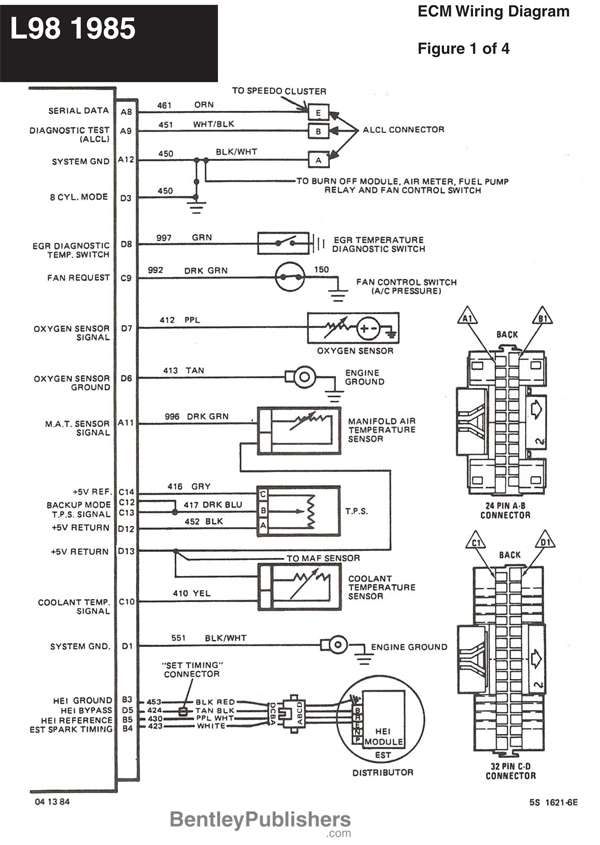
http://garage.grumpysperformance.co...lay-switch-locations-and-info.728/#post-93196
Use of a separate and independent oil pressure test gauge certainly would not hurt to verify the engine oil pressure
Engine Oil Temperature Sensor. (lower sensor above oil filter) 185 Ohms @ 210 F, 3400 Ohms @ 68 F, 7,500 Ohms @39 F.
https://www.harborfreight.com/engin...ent=&msclkid=ae03e71bd30b175c02b9b9fff2b0cb38
if you had a c4 corvette this might also help
tracking down the problem getting the engine started
If your car won,t start consistently, you need to isolate the problem to the source, you can,t isolate the cause without understanding the process, so you may as well start looking into how and why each step in the process starts , and how each step functions and triggers the next step. your...garage.grumpysperformance.com
1988 C4 Instrument Cluster Has Stopped Working
have a 1988 C4 that I had to replace the wiring harness and before installing. I made sure all joints were soldered and all wires were good. When finished installing I did not have my instrument cluster. I do have all the idiot light, blinkers, high beams. They bright and dim as they are...garage.grumpysperformance.com
Relay/s, Voltage Drop/s, Current Flow, Grounds and ... more
A relay is nothing more than a device that uses a low-current signal to operate a high-current circuit, he solenoid on your starter is a type of relay that uses the low-current signal from your starter switch to operate the high-current circuit between the battery and the starter motor...garage.grumpysperformance.com
c4 & c5 corvette trouble codes
if your corvette won,t start or run, don,t panic its usually easy to locate the problems source, buy a CHEVY SHOP MANUAL FOR YOUR YEAR CORVETTE! RULE#1 never assume a damn thing ISOLATE ,TEST AND VERIFY http://www.professionalequipment.com/ex ... ermometer/ Wide temperature range from -58 to...garage.grumpysperformance.com
cooling off that c4 corvette
your stock corvette http://garage.grumpysperformance.com/index.php?threads/thoughts-on-cooling.149/page-3#post-107697 has a rather marginal cooling system if your engines been modified for significantly higher hp levels, that cooling system can be significantly improved upon.I run into this...garage.grumpysperformance.com
https://www.autozone.com/diy/repair...ring-diagrams-repair-guide-p-0900c1528008fd94
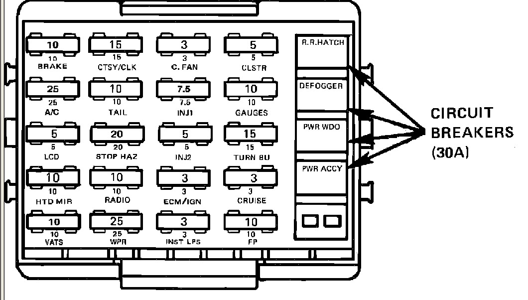
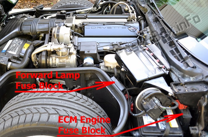
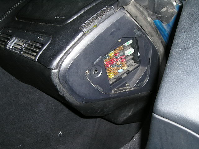
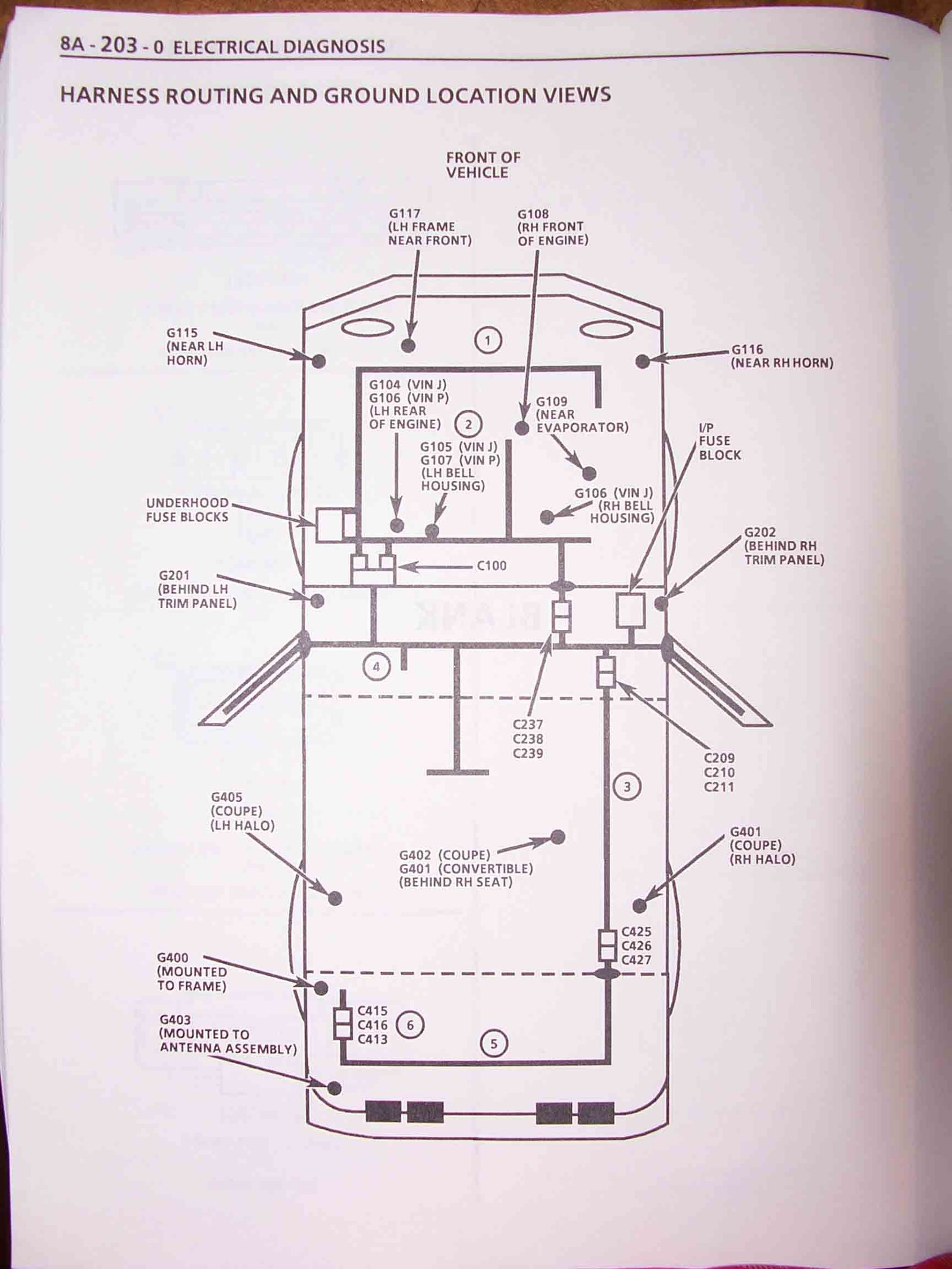
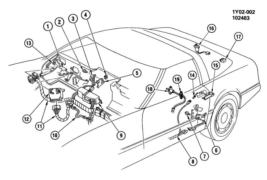
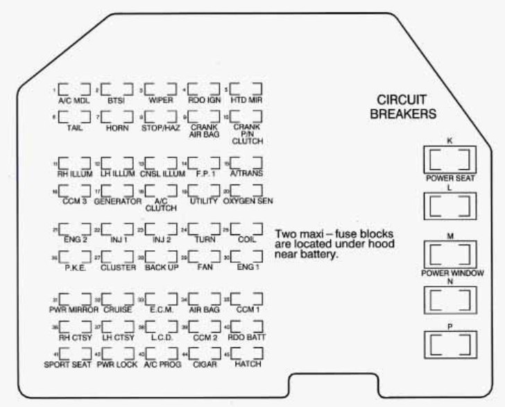
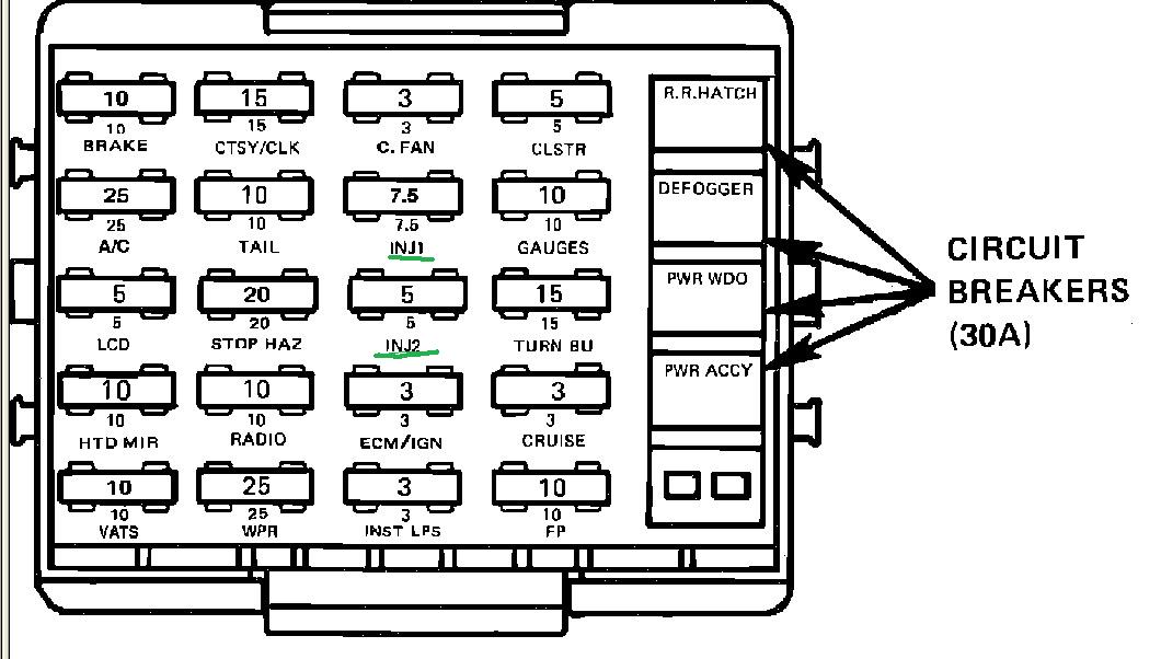
CHECK ALL YOUR FUSES WITH A MULTI METER
obviously check all your fuses
related threads
http://garage.grumpysperformance.co...lay-switch-locations-and-info.728/#post-93196
http://garage.grumpysperformance.com/index.php?threads/oil-system-mods-that-help.2187/
http://garage.grumpysperformance.com/index.php?threads/testing-a-tps-sensor.15446/#post-91265
http://garage.grumpysperformance.com/index.php?threads/oil-pressure-falls-off.10184/
http://garage.grumpysperformance.com/index.php?threads/code-scanners-software.3096/
http://garage.grumpysperformance.co...your-c4-corvette-runs-badly.15212/#post-87228
http://garage.grumpysperformance.co...g-tpi-crossfire-or-lt1-vette.1401/#post-39419
http://garage.grumpysperformance.co...ain-t-running-right-check-list.768/#post-2762
http://garage.grumpysperformance.co...ts-wrong-start-with-the-basics.609/#post-5672
Last edited:
