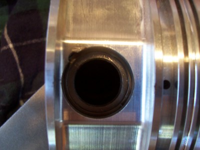
piston wrist pins, one really over-looked part.

grumpyvette

Administrator
Staff member
http://www.flatlanderracing.com/jepistonpins.html

http://garage.grumpysperformance.com/index.php?threads/snap-ring-pliers.16346/

stock wrist pins and the combo of forged piston and longer connecting rods allowing a higher pin or compression height piston,of lower total weight,especially when compared too cast pistons which are rather heavy and often are over looked,as a potentially upgraded component. thinking thru the use of all the components used and what they are made of and the weight , has benefits, those, components made of stronger and lighter aftermarket forged pistons with free floating piston pins (wrist pins)made from tapered tool, or even rather exotic titanium alloy, steel wrist pins can be used to reduce significant reciprocating weight
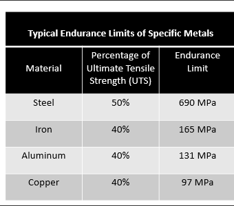
stressx4.png

http://www.tpub.com/content/engine/1403 ... 37_104.htm

http://www.beckracing.com/page10.htm

http://garage.grumpysperformance.co...in-height-compression-height.5064/#post-66240

http://www.enginebuildermag.com/2018/02/performance-pistons-101/

viewtopic.php?f=50&t=11029&p=48839#p48839

http://www.zoro.com/g/Snap Ring Tools/00059785/

http://www.bmeltd.com/Wristpin.htm

http://www.superchevy.com/how-to/engine ... m#cxrecs_s

http://www.kb-silvolite.com/features.ph ... ad&F_id=36

viewtopic.php?f=53&t=5064&p=14370#p14370

http://www.circletrack.com/enginetech/c ... index.html


http://www.probeindustries.com/Wrist_Pins_s/80.htm

http://www.flatlanderracing.com/ross_4340pins.html

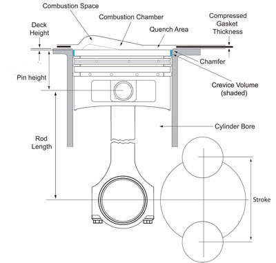
common sbc pin height info
Specs
  • Comp Height 5.565" Rod - 1.561
  • Comp Height 5.7" Rod - 1.433
  • Comp Height 6.0" Rod - 1.13
  • Pin Diameter - 0.9272
jep-094-050-ct.jpg

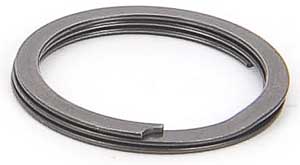
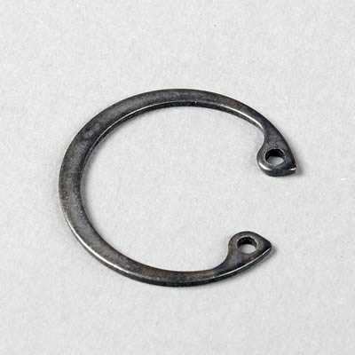
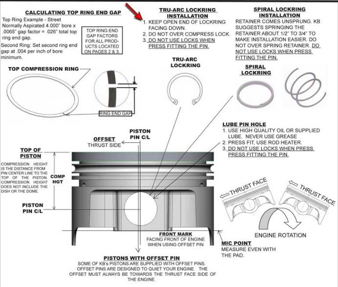
Install Tru-Arcs with the open ends pointing down only and make sure the flat side (with the sharp corners) faces out.
jep-927-073-as_w.jpg

sbcpistonnotch.jpg

SHC-947412_XN.jpg


if you have free float piston pins your most likely familiar with these
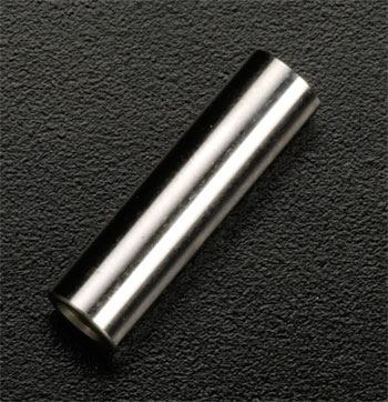
chromepistonpin.jpg

pin1.jpg

pin2.jpg

wristpin.gif


TaperedPin.jpg

taper1.jpg

taper1a.jpg


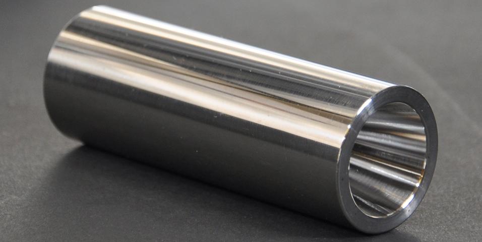
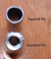
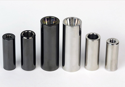
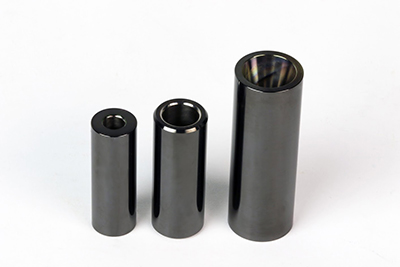
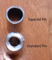
taper pins are lighter because the internal diameter is thinner towards the outer ends this reduces weight without reducing strength IF THE STEEL USED IS TOP QUALITY HEAT TREATED TOOL STEEL, BE AWARE there CHEAP SUB STANDARD CLONES that are not as well made.. quality aftermarket tool steel ,tapered tool steel piston pins usually cost $15-$30 EACH
taper1b.jpg

lockkb.jpg

tool+spiral_locks.jpg


newpincomparison.jpg

in rod for full floating pin, to snap ring (End play 0.0 - 0.005"
the stock style piston pin is usually fairly heavy
http://kb-silvolite.com/pins.php
the aftermarket ,tapered style can be just as strong, or even stronger due to better materials and heat treating of the component, better hardening, tempering etc. and several grams lighter in weight allowing smaller crank counter weights and lower balancing costs
Most guys order a set of pistons or a rotating assembly and never think for two seconds about the wrist pins that are usually included, but that's a mistake in some cases.
yes the tapered pins cost more but they also tend to weigh less and thus put less stress on the engine at high rpms.
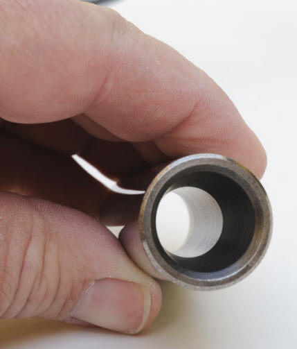
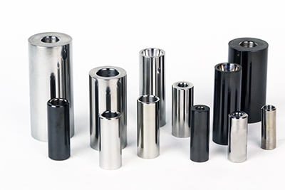
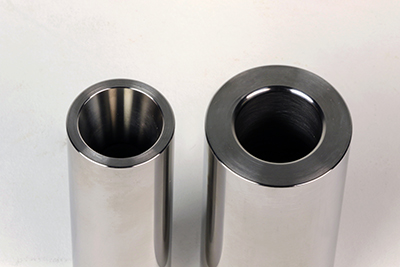
most piston wrist pins look like thick tubes with a mirror chrome finish, but theres also better quality wrist pins available made from far stronger and more expensive steel or titanium with the internal area rather hourglass shaped, where the hole thru the center tappers from a large outer end to a smaller central diam. that saves weight without sacrificing strength
pin1.jpg

one BIG ADVANTAGE to use of floating pin pistons and connecting rods it the ease of mixing and matching components and locations to minimize quench, or deck height differences during the install process
pinbut2a.jpg

http://blog.wiseco.com/what-are-wrist-pin-buttons

https://www.musclecardiy.com/performance/how-to-build-racing-engines-piston-technology-guide/
002-pin-buttons-wiseco.jpg


DSC_0010.jpg


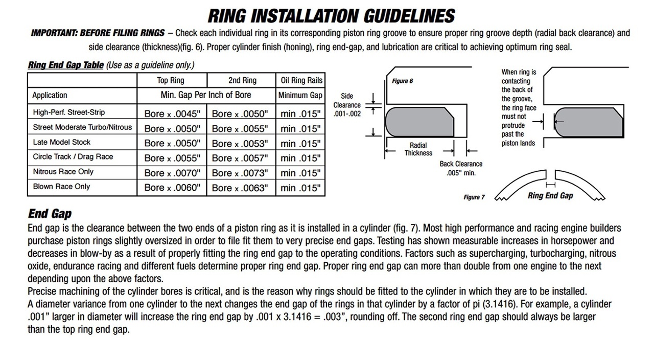
Second compression rings are really misnamed since their primary function is to assist with oil control. Most ring manufacturers hold that the second ring is about 85 percent devoted to oil control and only 10 to 15 percent to compression sealing. Its main mission is to scrape oil missed by the oil ring to that it doesn’t find its way to the combustion chamber to contaminate the fuel mixture. Since heat is not an issue with the second ring, a conventional cast-iron ring with a reverse bevel and tapered face is still employed with the primary task of scraping oil.
256.jpg

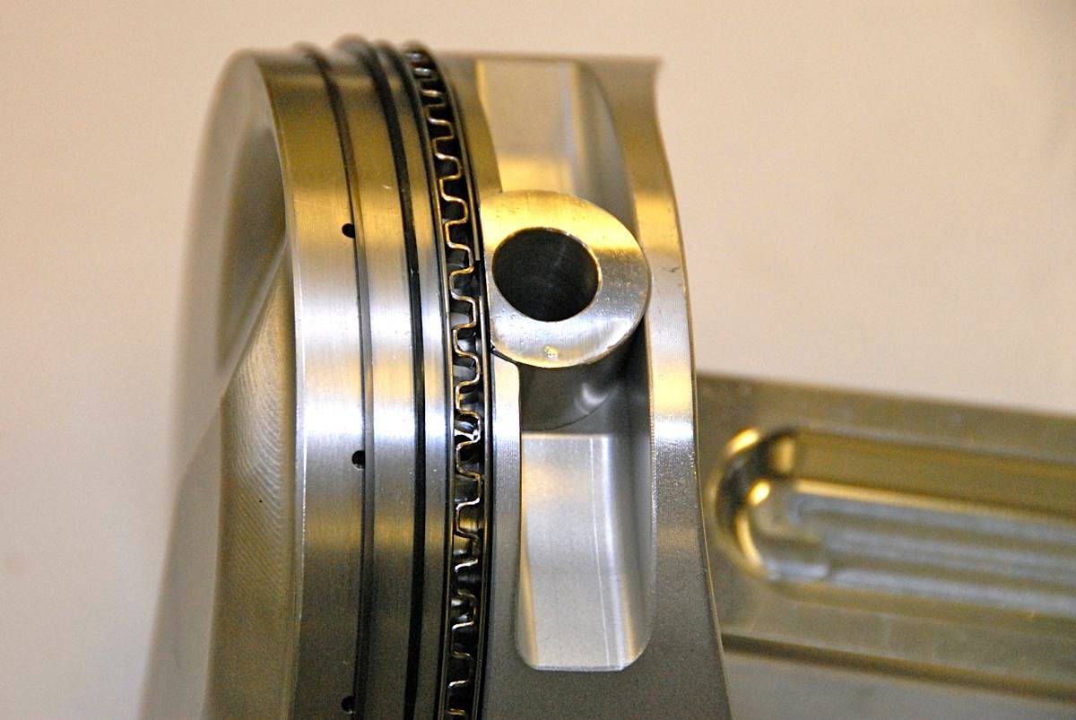
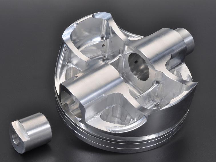
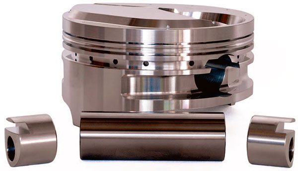
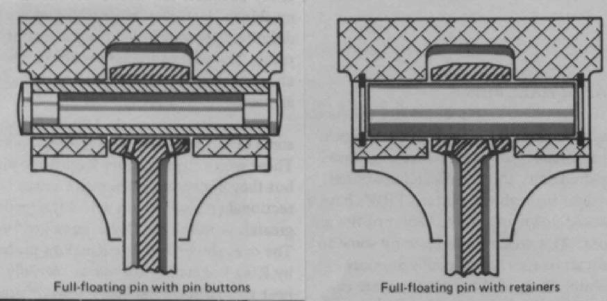
Where the pin bore encroaches on the oil ring groove, most applica¬tions use an oil ring support rail with a shorter inboard pin. The alternative is to use pin buttons with machined ring grooves that serve as oil ring supports. The buttons control pin placement and ring support, and they are much easier to assemble than the standard Spirolox or Truarc rings.
pinbut1.jpg


floatfit1.jpg

floatfit2a.jpg

floatfit4a.jpg

floatfit3.gif

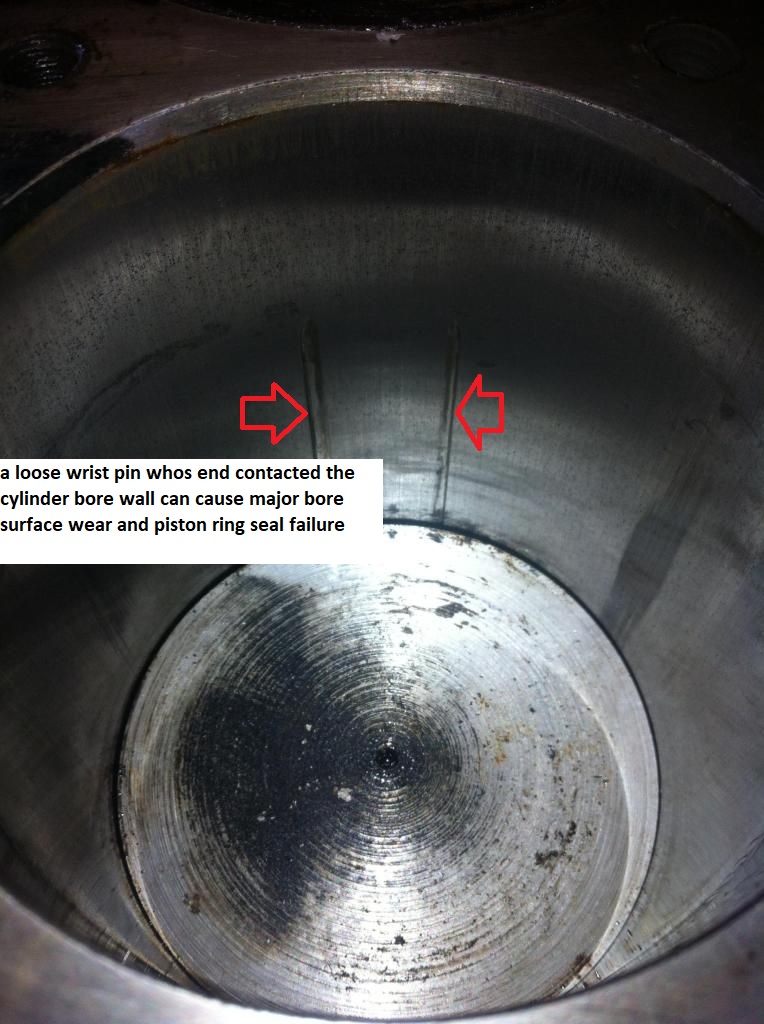
loosewrist.jpg


pinbut2a.jpg

OBVIOUSLY the PIN BUTTONS upside down here to better show the ring clearance groove, it might seen that the pin retention buttons will wear the bore but in most cases the combined length of the two buttons and piston pin were several thousands less than bore diam, and in many cases the lower oil rings retain the buttons

BACK IN THE 70s pin buttons were used as they made free float piston assembly easy and in cases where the pin intersected the oil ring they helped support the oil ring
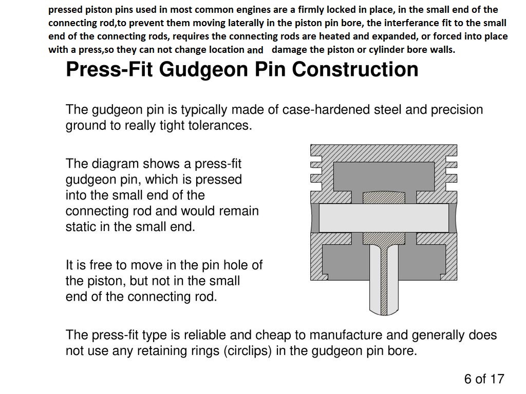
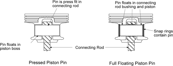
When a pressed pin is installed,into,and held in place by the small end of the connecting rod being an interference fit in a connecting rods small end, where during use its clamped firmly in place, most shops put the smaller end of the connecting rod on a connecting rod heater device that heats the piston pin end of the connecting rod to specific heat range so it expands slightly.(just enough to allow the pin to slide thru easily) With the piston sitting is a little V-block or rounded cradle, they put the rod into the piston in line with the pin bore location centerline and insert then press in the pin. The pin slides in easily since the hole in the rod has expanded, by the heat, but. Once the rod contacts the pin and piston these act like a heat sink, drawing off heat rapidly so it cools rapidly , the hole in the small end of the connecting rod tightens up as it contracts and the pin will not slide from its location. This takes only a few seconds to contract because the pin, piston and rod body draws the heat out, as soon as the heat source is removed.
WATCH THESE VIDEOS

http://www.youtube.com/watch?v=cJJI9bml ... re=related

http://www.youtube.com/watch?v=uTpRfREY ... re=related

http://www.enginebuildermag.com/2007/04/performance-connecting-rods/

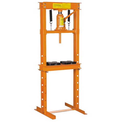
To remove the pins, you don't have the ability of being able to heat just the small end of the rod up with the heater so that it alone expands and allows the pin to slide out. You have to press it out, with a hydraulic press and the pins soaked in light oil then pressed out in a jig that holds the piston assembly.
The piston body being aluminum is easy to deform and its the piston that is resisting the forces of the pin removal hydraulic pressing operation.
pistons and pins should be carefully cleaned with a solvent bath then the pin lubed before dis-assembly to prevent damage from micro crud thats likely to form in a running engine on the piston pin bores.
008-wiseco-ring-groove-tech-pistons.jpg


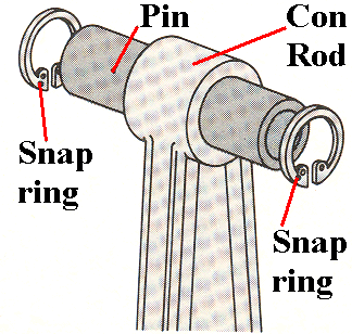
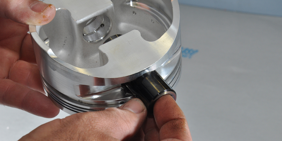
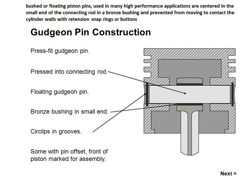
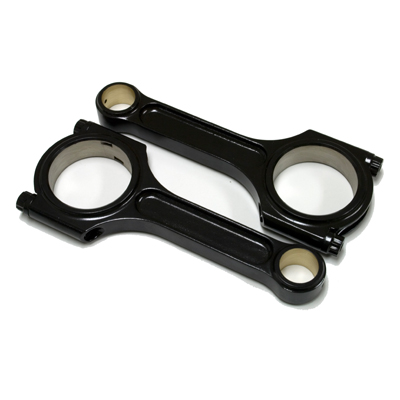
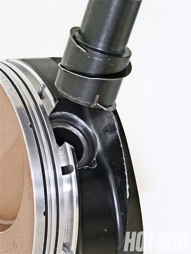
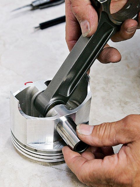
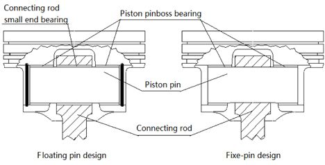
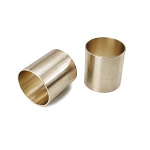
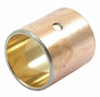
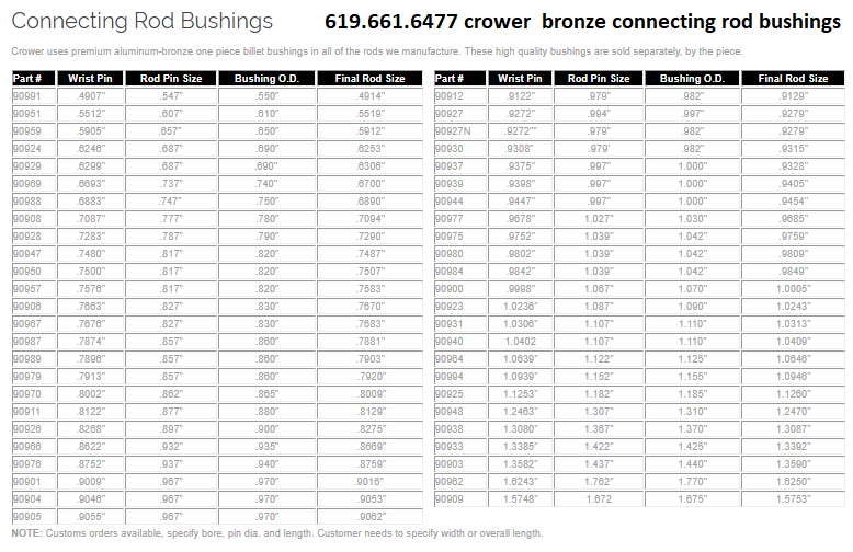
FULL FLOATING , piston pins are a slide fit in both the small end of the connecting rods and the piston pin bores and are allowed to rotate freely in both the small end of the connecting rod and the piston pin bores, this reduces friction and allows easy hand assembly, but it requires the use of locking snap rings or spiro-locks to hold the pin in its intended location in the pin bore in both the small end of the connecting rods and the piston pin bores. because the small end of the connecting rod has a pin that moves this end frequently has a bronze sleeve inserted and an oil hole drilled to increase lubrication on the piston pins
90912_19.jpg

825146M1.jpg


https://goodson.com/blogs/goodson-gazette/the-ins-and-outs-of-pressing-piston-pins-and-bushings

https://www.summitracing.com/search/section/connecting-rods/wrist-pin-bushing-material/bronze

https://pitstopusa.com/c-134461-eng...rod-parts-accessories-wrist-pin-bushings.html

https://goodson.com/blogs/goodson-gazette/the-ins-and-outs-of-pressing-piston-pins-and-bushings


crowerbush.png

ibeamcoatsmall.jpg


Guys frequently ask me why I don,t refurbish stock rods or use pressed in piston pins on 90% of my engine builds, its for both economic and strength reasons,
let me say this, Ive build close to 180 engines or more MINIMUM now over 40 plus years (I lost count)and I use the local machine shop to instal pressed in pins or I talk the guys into free float piston designs and I OWN a 12 ton press and several torches, simply because its a P.I.T.A. to fix if you screw it up,and cheap to have done.
now obviously I could buy a rod heater and have the tool, but just using the far stronger aftermarket connecting rods and free float pistons makes far more sense to me, than screwing around with weaker rods and harder to assemble pistons
a good aftermarket connecting rod with 7/16" ARP rod bolts and a cap screw rod design with free float piston pins is easily 150%-200% stronger than refurbished stock connecting rods and after all the time and effort and new rod bolts , polishing, magnifluxing, resizing etc, it just makes zero sense to refurbish inferior rods or deal with press in piston pin
s


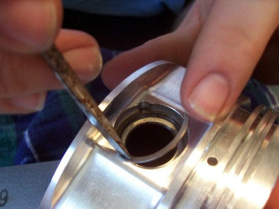
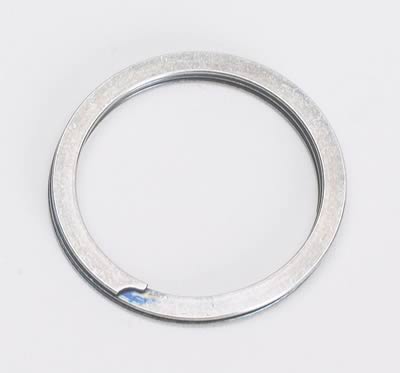
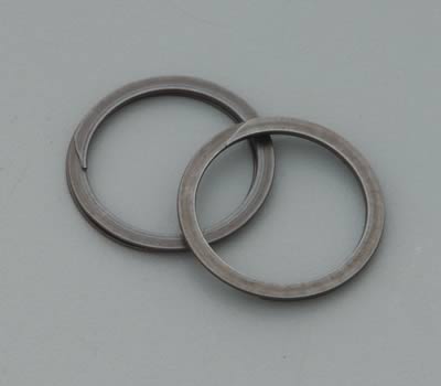
this is were the SPIROLOCS give you a noticeable advantage, they are basically a semi flat spring,with one flat side and one slightly micro-curved side, you pull them out to stretch them then spiral them into place (two slightly curved side BACK TO BACK) flat sides facing out, they act as mini springs taking up any residual space thus keeping the piston pin centered, and resisting any length wise travel.
spiro6.jpg

spiro7.jpg

spiro0.jpg

spiro1.jpg

spiro2.jpg

spiro3.jpg

spiro4.jpg

spiro5.jpg


related info


http://kb-silvolite.com/article.php?action=read&A_id=9

http://www.smalley.com/pdfs/spiral_reta ... emoval.pdf

http://webpages.charter.net/beckracing/page10.htm
viewtopic.php?f=53&t=978
http://www.ustream.tv/recorded/221556

http://www.angelfire.com/mech/danielspo ... rolox.html
read these threads


viewtopic.php?f=53&t=247

viewtopic.php?f=53&t=852

viewtopic.php?f=53&t=510

viewtopic.php?f=53&t=1168

viewtopic.php?f=53&t=4472
 
Last edited by a moderator:
BUT GRUMPYVETTE
my rods are press pin pistons and I was told to heat them in a rod furnace then drop the pins in to install them?


YES thats commonly done that way, and with stock pistons and rods you can do that, but Ive always said if your going to get decent pistons and rods get the full float style, the pins rotate in both the pistons and rod for less friction, the pins smaller and lighter and the pistons tend to be far better quality, and you can assemble and dis-assemble the rods from the pistons for inspection by hand!
while were talking about installing stuff thats a press fit....
heating bearings enough to expand them a good deal,is usually a BAD IDEA!
it can burn off protective finishes
it can distort the clearances
it can ruin the heat treatment
it can warp the surface finish
it can ruin the bond to the backing material,
it can cause soft spots in the surface, etc.

you can usually find these on sale for under $120

http://www.harborfreight.com/cpi/taf/Di ... mber=33497

yes its a total p.i.t.a. to take the differential out to work on it, but at times its the smart choice.
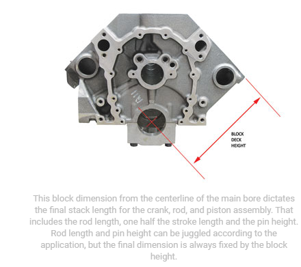
http://www.enginebuildermag.com/201...ton-compression-height-and-crankshaft-stroke/
deckh.jpg

deckh.png

Obviously if your only running the temp up with something like a hair drier or a heat gun to 140f-250f or so as oil always gets that hot, its most likely having zero bad effect, but by 400F PLUS if not controlled correctly , can easily cause problems in some rare cases,
400F is not a problem, pistons normally see that temp range occasionally, but anytime you say HEAT,IT UP! to most guys...
out comes the propane or acetylene torches,and all precise control on temps becomes a joke.
IVE gone the reverse route in most cases and packed cranks, axles, piston pins, etc in dry ice for an hour or so then spray them with a fine mist of oil and in many cases you can slip bearing into place if the clearances are just a bit tight.
a HYDRAULIC PRESS is a great tool, but the truth here is that 99% of the pressed in piston pin applications are best handled with a local machine shop having the correct rod heater and tools required rather than having you do it yourself

Btw I have not (VOLUNTARILY) used or advised the use of pressed pin pistons, in connecting rods for years, I'VE always preferred bronze bushed rods with free float piston pins and dual spirolocs on each end of the wrist pins or dual internal spring clips
I find it really amazing how often I see guys get 1/2 way into an engine assembly process and they suddenly want to change or modify some major component,
now in most cases that get expensive and the change will result in having to make corresponding matching changes in other
components
you could have saved a great deal of time and money,
by taking extra time in the research, phase of the engine build,
by simply shopping carefully,for each component and calculating how it will match the other selected components and it generally helps if you deal with a well known major name brand manufacturer and ask lots of carefully thought out questions and know exactly what your trying to accomplish and what your options are that you would want or prefer to have, especially in major components like the rotating assembly, and valve train components ,
ordering custom made 2618 forged aluminum, pistons with,
light weight tool steel wrist pins,
gas ports,
and thermal coated domes,
and friction reducing skirts,
a BALANCED 4340 forged steel rotating assembly,
with connecting rods that use ARP 7/16" rod bolts of the correct for the application strength rating.


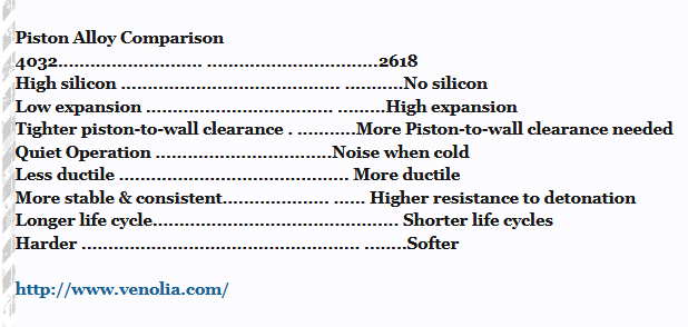
Piston Alloy Comparison
4032..
......................... ................................2618
High silicon ......................................... ...........No silicon
Low expansion ................................... .........High expansion
Tighter piston-to-wall clearance . ...........More Piston-to-wall clearance needed
Quiet Operation .................................Noise when cold
Less ductile ........................................... More ductile
More stable & consistent.................... ...... Higher resistance to detonation
Longer life cycle.............................................. Shorter life cycles
Harder .................................................... ........Softer

http://www.venolia.com/

most crate motors use pressed in piston pins,
not free floating piston wrist pins
free floating piston wrist pins rotate in the connecting rod small end and in the piston pin bores
pressed wrist pins are designed to be firmly locked in the connecting rod small end and only rotate in the piston pin bore's


most stock engines use pressed wrist pins, it requires pistons designed to use free floating wrist pins to use free float or bushed wrist pins.

if the wrist pins are designed to move in the rods small end the piston will be designed to keep the wrist pin centered in the piston,
pistons without a design to retain the wrist pin use pressed in wrist pins,
that should not be free to move in the connecting rod small end.

read these links, (below) and Id certainly pull a rod and piston,
and determine exactly what type of piston and wrist pin combo your dealing with for sure.


http://garage.grumpysperformance.co...g-and-installing-connecting-rods-pistons.247/

http://garage.grumpysperformance.com/index.php?threads/what-con-rods-would-you-buy.942/#post-67580

http://garage.grumpysperformance.co...ing-rod-strength-h-vs-i-beam.1168/#post-41255

http://garage.grumpysperformance.com/index.php?threads/reusing-stock-connecting-rods.702/#post-975

http://garage.grumpysperformance.com/index.php?threads/connecting-rod-weights.3540/#post-9394

http://garage.grumpysperformance.co...market-4340-connecting-rods.13321/#post-72048

Last edited: A moment ago


RELATED LINKED INFO
http://garage.grumpysperformance.com/index.php?threads/snap-ring-pliers.11029/#post-48839

http://garage.grumpysperformance.com/index.php?threads/precision-measuring-tools.1390/

http://garage.grumpysperformance.com/index.php?threads/piston-suppliers.2208/#post-19329

http://garage.grumpysperformance.com/index.php?threads/piston-related-info.110/#post-31943

http://garage.grumpysperformance.com/index.php?threads/types-of-crankshaft-steel.204/#post-240

http://garage.grumpysperformance.co...ore-clearance-on-your-block.14251/#post-72471

http://garage.grumpysperformance.co...lling-connecting-rods-pistons.247/#post-57737

http://garage.grumpysperformance.co...y-in-building-a-good-engine.11682/#post-54682

http://garage.grumpysperformance.co...a-scat-rotating-assembly-be.11495/#post-52962

http://garage.grumpysperformance.co...-calculators-and-basic-math.10705/#post-46582

http://garage.grumpysperformance.com/index.php?threads/rod-bolts-rpm-vs-stress.341/#post-68856

http://garage.grumpysperformance.com/index.php?threads/rotating-assembly-bearings.9527/#post-70329

http://garage.grumpysperformance.com/index.php?threads/piston-to-bore-clearance.4630/#post-12417

http://garage.grumpysperformance.co...n-you-plan-for-quench.11298/page-2#post-51613

http://garage.grumpysperformance.co...-displacement-street-engine.10961/#post-48185

http://garage.grumpysperformance.com/index.php?threads/piston-coating-deburring.4516/#post-16279

http://garage.grumpysperformance.com/index.php?threads/engine-balancing.3900/#post-10338

http://garage.grumpysperformance.co...ns-one-really-over-looked-part.978/#post-1711


https://www.chevydiy.com/chevy-small-block-cranks-rods-and-piston-guide

http://engineprofessional.com/articles/EPQ416_50-54.pdf

http://trendperform.com/files/1-News-Downloads/pg-00-00-t-wrist-pins-_.pdf

https://www.jepistons.com/blog/wrist-pin-locks-different-types-and-how-to-install-them

https://www.hotrod.com/articles/ctrp-0801-piston-pin-tool/
 
Last edited by a moderator:
IF you've ever needed to use spiro -locks ,READ THRU THESE LINKS

http://www.hotrod.com/pitstop/hrdp_1002 ... index.html

http://www.circletrack.com/enginetech/c ... index.html


Spirolock Tool
What company makes a spiral-lock installation tool? Sore fingers and thumbs from installing the locks into pistons is a real drag.
Randy Guynn
Pasadena, TX

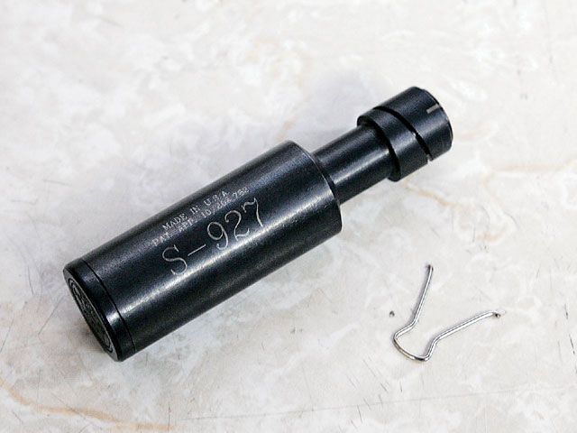
We've all got plenty of old wounds from installing Spirolocks in pistons and hose ends on stainless steel braided hose. Piston pin bores can also get torn up by the small screwdrivers often used as improvised Spirolock installation and removal aids. The solution is, of course, getting the right tool for the job. For piston pin locks, Lock-In-Tool sells Spirolock as well as round-wire-lock installation tools; they're available in 4140 hardened steel for repeated use by the professional engine builder or in more affordable lightweight plastic for the home builder. Order by type of retainer (Spirolock or round wire), tool material (steel or plastic), and piston pin diameter. Also available from Lock-In-Tool is The Lockbuster, which makes short work of removing those pesky Spirolocks.
Lock In Tool Spirolock Tool
The Lock-In-Tool is available...

read full caption
Lock In Tool Spirolock Tool
The Lock-In-Tool is available for most popular pin diameters in steel and plastic. These examples are for 0.927-inch-od small-block Chevy pins. The steel version (left) fits spiral-type locks; on the right is a wire-lock installer in plastic. The clip inserts into the opposite pin groove to prevent the pin from sliding out of the piston during initial installation.

Spirolock In Action
Using the installer, Spirolock...
spirolocktool.jpg


80474spirolockj.jpg

80474spirolock2.jpg


read full caption
Spirolock In Action
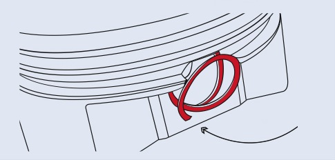
Using the installer, Spirolock installation now takes seconds instead of minutes. Simply spin the lock onto the tool until the end of the lock aligns with the tool's registration mark. Tilt the tool slightly to the left and insert it into the pin bore to place the lock into the groove. Square the tool and turn counterclockwise until the lock spins completely into the groove.


Source
Lock-In-Tool
Waxhaw,NC 704/843-5477 http://www.lockintool.com

Piston Pin Spiro Lock Installation Procedures


When the locks are properly seated, only half of the lock will be visible above the groove. Most pistons that require spiral locks will need four locks per piston, two at each end of the pin (check with your pistion supplier).


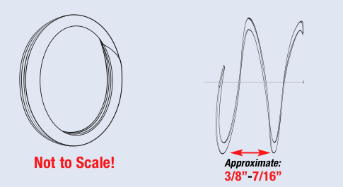
When installing Spiro locks, grip each end of the lock and pull apart (approx. 3/8˝-7/16˝). The lock will resemble a small coil (Figure 1). The lock can then be spiraled into place almost as if you were screwing them into a groove (Figure 2).

WARNING:It is important that the correct numbers of locks are installed in each piston or severe engine damage may occur. Do not over stretch spiro locks and do not reuse spiro locks.

–Tech Tip courtesy of JE Pistons
 
Last edited by a moderator:
Connecting Rod Reconditioning: More to it than you might think


The processes used to recondition connecting rods may vary a little from one rebuilder to the next, but the end goal is always the same - straight rods with round bores

By Brendan Baker

Brendan Baker

The connecting rod plays a vital role in the engine. But a connecting rod is under tremendous stress, with the weight of the piston sitting on top, changing direction thousands of times per minute. This continuous stopping and changing of direction combined with the weight of the piston and speed of the engine hammer on the bearings and torture the rod bolts which hold everything together.

Proper geometrical alignment and bearing surfaces that are smooth and perfectly round is the best way to ensure long engine life and happy customers. Any unwanted lobing, chatter or misalignment, particularly in engines that operate at high rpms, will affect the engine's efficiency.

One of the most important aspects of rebuilding an engine is to recondition the connecting rods. There are many different types of connecting rods from cast steel to powdered metal "cracked" rods to all the various types of performance rods. The processes used to recondition this engine component may vary a little from one rebuilder to the next, but the end goal is always the same - straight rods with round bores. Sounds simple, but like anything worth doing, there's always more to it than you think.

Typically, reconditioning rods involves cleaning them thoroughly, then checking them with magnetic particle inspection for any cracks. Then the rods are checked for straightness because any bend or twist in the rod may result in oil clearance problems and likely lead to a failure.

A visual inspection of the rods will also include looking for any signs of overheating, which may be indicated by a "bluish" appearance. If the rod has been overheated, its structural integrity may have been compromised, according to the rebuilders we interviewed for this article.

"If a guy has overrevved his engine, we go through and magnaflux all the parts," says Kenny Burns, Harry's Machine Works, Dodge City, KS. "Connecting rod material is typically pretty good, but sometimes the machine quality leaves something to be desired. Therefore, we check everything, even brand new rods."

On the performance side, some rebuilders will check the hardness before declaring them fit for the junk pile. "You can test the heat treatment with a Rockwell tester," says Roger Friedman, Dyer's Top Rods. "We know what our rods should be. They're usually in the 42-43 range on the Rockwell C scale. If a rod got hot enough to change that, it's junk to us."

Friedman cautions that color isn't always a true indicator, however. "We'll sometimes see some rods that were affected when an oil pump belt came off, for example. If you catch them soon enough, they will still turn color, but if the rods test okay, we will shot peen them, re-cut and resize them and reuse them."

After the rod has been cleaned and inspected thoroughly, it should be put back together with the rod bolts torqued. With a stretch gauge, check each rod bolt for proper stretch. If the stretch is out of spec, then replace the bolt. While some engine builders say that it is safer and less expensive to just replace the rod bolts instead of measuring the stretch, others say that practice really depends on the application, because some high performance rod bolts can be quite expensive.

After the caps are torqued on with acceptable rod bolts, measure the big end bores. This will help you to determine how much to take off the caps and to what size you'll need to hone them. In general, you want to take off as little material as possible to make the bore round again. After you hone the big end, measure the rod to see what size bushing you need to put in the pin end.

"The ultimate goal when reconditioning rods, is to come up with a set of rods that are straight and of the correct length," says Jay "Dr. Diesel" Foley, of Foley Engines, Worcester, MA. "In common four- and six-cylinder gasoline and diesel engines, the rods must be machined back to original specs with no more than .0025" of bend and no more than .00425" of twist. A rod with too much bend will limit oil clearance from one side to the other and possibly lock up the engine at the pin end or at the thrust on the crankshaft. In addition, they must have round and concentric bores, and the fasteners must also be able to withstand the stresses of a modern engine."

Once the connecting rods are bored and honed, then you can put the proper size bushing in the small end, which itself is a very important step. "We are very concerned about the piston-pin bushing relationship," says Foley. "We always press out the old piston-pin bushing and install new ones. But that is only half the battle. To ensure that the bushing won't rotate, we expand it to conform to the small end bore. To expand this bushing we press a hardened steel ball through the ID of the new bushing. This will lock in the new bushing and prevent it from spinning in the bore. If you heat the rod to install the new bushing, you should allow it to cool before you expand the bushing with this broaching technique. Then grind the cap to the correct center-to-center dimension and hone the big end and install new rod bolts."

According to Harry's Machine Works' Burns, keeping the rod straight is very important. However, one of the difficulties his shop faces is finding aftermarket wrist pins that are the correct size. "Some aftermarket suppliers are making wrist pins that are supposed to be the same size as OE but they are not," he explains. "We have had a hard time trying to get the right sizes. Sometimes the pins are .001? to .003? off the OE specs. Within that application we have seen differences of up to .003? and we're trying to keep the tolerance within .0002" to .0003"."

Burns says that his shop uses a similar process to Foley's for reconditioning connecting rods. Both Foley Engines and Harry's Machine primarily rebuild diesel engines. Rebuilding diesel rods isn't much different than gas engine rods, except they're much bigger and the center-to-center distance is has to be exact. Since diesel engines operate on a compression cycle, rod lengths have to be correct. "We can shorten them or lengthen them," Burns says about diesel rods, "it just depends on how much has been taken off the block. So the center-to-center distances are critical."

Fractured Rods
Fractured rods are a fairly new phenomena. Ford was one of the first on the automotive side to use a fractured rod in the 4.0L engine, which was one of its first new generation engines in 1990. The fracture method has proven to be less expensive for manufacturers and it produces better quality because it is forged in one piece and then 'cracked' at the rod cap.

"Before fractured rods were invented, conventional rods were two components," says Dave Hagen of the Engine Rebuilders Association (AERA). "You would have one piece, which was the cap and another that was the beam. The two pieces were close enough to bolt together; then you would have to do several machining operations to get the center-to-center distances correct. The fractured rod, on the other hand, is a powdered metal rod that allows the manufacturer to pop it out like an egg with very little machining to make the size exactly right. It comes out essentially the final size and then is broken at a scored line that is part of the design. Once it's broken or 'cracked,' it's done. It can be manufactured for far less cost than a traditional rod and it's a more durable component."

According to Hagen, the inside diameter of a fractured rod bore is scored and then some pressure is applied until it snaps. The resulting split is like a piece of china that has been broken. It has a very distinctive surface that custom fits together. The fracture has more surface area because you have peaks and valleys, and the alignment is more accurate since the cap only fits together one way.

For rebuilders, there's not much you can do with fractured rods. You can't cut the caps because of the unique break on each one. And for the most part, you cannot hone the bore because there are very few oversize OD bearings available for them. Hagen says that some suppliers carry oversize OD bearings for the big end of the more popular models, like the modular 4.0L and 4.6L Fords, but it's uncertain if there are any bushings available for the pin end. So there's a little bit of rebuildability with fractured rods but not much.

Now, some heavy-duty manufacturers are going to fractured rods. "There are some heavy-duty manufacturers making them, like John Deere is coming out with some now, but with fractured rods we can't do much with them," acknowledges Harry's Machine Works' Burns. "We measure them to check the size, and that's about all we can do until there are oversize OD bearings available."

New Methods
For years, connecting rods have been honed on specialized rod honing machines, which are available from many leading manufacturers. These machines have been the standard, produce excellent results and are still widely used throughout the industry. However, Sunnen and Rottler have both recently come out with new systems that take a totally different approach to rod reconditioning.

Sunnen's system is called the KGM-1000 Krossgrinding System®. The KGM system utilizes an easy-to-use computer control, diamond tooling and a feed system that gives the operator high accuracy and speed in the production of precision reconditioned connecting rods. The company says the system is extremely accurate for honing connecting rods, and is capable of holding very tight tolerances, achieving accuracies of .00001" in straightness and .00015" in roundness.

Rottler has also designed a completely new system that works with the F-65 and F-67A multi-purpose machines. According to Rottler's Anthony Usher, the company wanted a system that could bore both the big end and the small end in one setup.

"When we decided to get into the rod reconditioning business," Usher says, "one of the big problems we saw was that rods bend and twist. When you have two setups you can sometimes create other problems. We decided to design a system where a rebuilder could lay the connecting rod horizontally and set it up so both the big end and the small end could be open. With both ends open you can machine both ends in one machine and in one set up and achieve perfect parallelism between the centerlines of both ends."

Rex Crumpton Jr., of Memorial Machine in Oklahoma City, OK, says his shop has both a Berco rod honing machine and a new Rottler system. According to Crumpton, both systems work excellent and he can achieve good results either way. Memorial uses the Berco machine for doing smaller stuff and the Rottler for reconditioning larger rods.

"Honing is excellent, there's nothing wrong with doing rods that way," says Crumpton. "But boring can be a bit more precise. You don't have to worry as much about stones loading up, which could produce taper. As long as you have a good operator who is paying attention, both methods work fine."
 
Written by David Reher

I come from a family of teachers, so perhaps I’m genetically programmed to stand in front of a classroom. Maybe that’s the motivation behind the engine building classes that we conduct regularly at Reher-Morrison Racing Engines. What I’ve discovered, however, is that a teacher learns as much from the students as the students learn from the teacher.

When a racer attending one of our seminars asks why we prepare a part a certain way, I have to think about the experiences that led us to adopt a particular technique or choose a specific engine component. A case in point is the lowly wrist pin – one of the most overlooked yet most important components in any motor.

The wrist pin is a crucial link in the chain that connects the power to the pavement. It has to withstand the full force of the cylinder pressure while accelerating several thousand pounds of race car. Yet racers who will gleefully study cylinder head airflow graphs and camshaft profiles for hours seldom give any thought to the wrist pins in their engines. Let’s face it: Wrist pins simply aren’t sexy.

I’ve built racing engines for more than 30 years, and have always subscribed to the belief that lighter is better. But recently I’ve had to reevaluate my thinking in regard to wrist pins. I’ve come to the conclusion that as power levels have escalated, many racers are using wrist pins that are just too light. I’ve also realized that some of the parts that extract more horsepower from an engine also increase the stresses on the wrist pins. Racing isn’t exempt from the rule of unintended consequences: Every solution breeds new problems.

When selecting parts for a racing engine, the general rule is “light is good.” For example, a lightweight crankshaft assembly require less power to accelerate than a heavy crankshaft assembly, and therefore more of the engine’s output can be used to accelerate the race car. But if the parts are so light that they deflect and deform under high loads, then the result is the exact opposite – more friction is created and more power is siphoned off in the form of heat that destroys the pins, pistons, and connecting rods.

In reality, more power equals more cylinder pressure, so we have to select parts that are appropriate to the engine’s power levels. Once you go beyond a set of off-the-shelf pistons, the choices of wrist pin material, diameter and wall thickness become critical.

When a customer orders a set of wrist pins, the first question I ask is, “How powerful is the engine you’re building?” A set of tool steel wrist pins with a .090-inch wall thickness might be fine for a small-block Super Stock engine, but a 1,000-horsepower big-block typically needs pins with .150-inch wall thickness – and the pins must be correspondingly thicker for a nitrous-injected engine. The wrist pins used in blown alcohol and nitro-burning engines illustrate just how strong the pins must be to survive under extreme conditions.

A catastrophic pin failure is an expensive way to learn that the pins are too light. Fortunately there are some early warning signs that indicate the pins are overstressed. Black streaks in the pin bosses or the small ends of the connecting rods are danger signs. In more advanced cases there may be aluminum welded to the pins from the piston pin bosses and rods (in the case of aluminum rods). With steel rods, look for signs of distress in the bronze bushings in the small ends of the rods. These problems are usually the result of wrist pin deflection, insufficient clearance or inadequate lubrication.

Wrist pin problems were rampant in Pro Stock several years ago, and the cure was to apply some very expensive coatings. Spending $800 for coated pins is not a cost-effective solution for most sportsman racers, however; the object is to make as many runs as possible at a reasonable price. Assuming that the wrist pins have adequate strength, it’s possible to head off many problems simply by ensuring that the pins have adequate clearance and lubrication.

The crankcase in an engine with a conventional wet-sump oil pan is awash in oil. If there is a condition that’s heating up the wrist pins or stressing the piston and rod bores, the sheer volume of oil in the crankcase will carry off the excess heat. But a well-designed oil pan with a kick-out, crankshaft scraper and a vacuum pump (or a good dry-sump system) will dramatically reduce the amount of oil in the crankcase. While an efficient oil system reduces windage and increases horsepower, it can also put the wrist pins in jeopardy – another instance of unintended consequences. In fact, the wrist pins in the even-numbered cylinders are often the first to show signs of distress caused by insufficient lubrication because they are on the side of the engine that has much of its lubrication stripped away by the crankshaft scraper and oil pan kickout.

In this situation, my recommendation is to increase the wrist pin clearance. Most engine manuals recommend wrist pin clearances between .0008 and .0010-inch for conventional engines; my advice is to run .0020 to .0022-inch wrist pin clearance in a serious drag racing engine. My perspective on engine clearances is straightforward: When in doubt, a little loose will seldom result in catastrophic failure, but a little too tight will almost always cause problems.

Remember that drag racing engines are usually stone cold when they go down the race track. We start the engine and get to the staging lights as quickly as possible because a cold engine makes more power than a hot one. Consequently drag racers don’t have the luxury of an extended warm up period to bring all of the parts up to operating temperature. In these circumstances, a little extra clearance is a good thing.

I’m an advocate of double Spirolox pin retainers. Yes, they are a pain to install and remove, but that’s exactly what’s needed in a pin retainer – a lock that won’t come out on its own.

Wrist pins aren’t glamorous, but they are absolutely essential to the health and well being of a racing engine. Don’t scrimp on pins; a few extra grams of wrist pin weight can increase your engine’s life expectancy.

http://www.probeindustries.com/

https://www.flatlanderracing.com/trwpistonschoose.html

http://aftermarket.federalmogul.com/en- ... 7ibJ7FwU4M

http://www.jepistons.com/

http://www.venolia.com/

http://www.wiseco.com/

http://www.trickflow.com/search.asp?Ntt ... wordSearch

http://www.flatlanderracing.com/manleypis-chevy03.html

http://www.rosspistons.com/information/

http://www.ariaspistons.com/

https://www.uempistons.com/
 
So I have some pretty heavy pin's here and need to make 138 H.p per cylinder and want the motor to be able to be able to take 162 H.P. per cylinder as a safety margin. My motor stock is a 2.2l lotus I4 blown DOHC... Which in its self is a mix of race car technology and plain carelessness. What I do know that is relevant is the fact that at 120+- ponies per cyl the stock forged rods pull apart but they are 850 grams! The replacements are 620gram 4340 H style. I am sticking with redesigned new stock pistons that are the same principal as the original but the gas porting and metalurgy are better than OE. They are chrome coated forged mahle and weigh 518.5 grams each. Now this wrist pin. it weighs 170 grams and is very typical looking. The other issue is on two of my pistons they require a lot of force to press out with my thumb... This is the first large piston pin I have ever pushed out but on all my small motors usually just a tiny bit of resistance is felt. No signs of ware after 8 months of road use. But I was thinking these pins feel heavy and with modern technology like the tapered pins mentioned above maybe I can shave off that 70 grams or so at least and retain strength? Id like to ask around starting here. But I also dont know who to call for some pins.
 
So I have some pretty heavy pin's here and need to make 138 H.p per cylinder and want the motor to be able to be able to take 162 H.P. per cylinder as a safety margin. My motor stock is a 2.2l lotus I4 blown DOHC... Which in its self is a mix of race car technology and plain carelessness. What I do know that is relevant is the fact that at 120+- ponies per cyl the stock forged rods pull apart but they are 850 grams! The replacements are 620gram 4340 H style. I am sticking with redesigned new stock pistons that are the same principal as the original but the gas porting and metalurgy are better than OE. They are chrome coated forged mahle and weigh 518.5 grams each. Now this wrist pin. it weighs 170 grams and is very typical looking. The other issue is on two of my pistons they require a lot of force to press out with my thumb... This is the first large piston pin I have ever pushed out but on all my small motors usually just a tiny bit of resistance is felt. No signs of ware after 8 months of road use. But I was thinking these pins feel heavy and with modern technology like the tapered pins mentioned above maybe I can shave off that 70 grams or so at least and retain strength? Id like to ask around starting here. But I also dont know who to call for some pins.
Lightweight Wrist Pins are not wanted in Turbocharged or Supercharged Engines.
They Will Fail Catastrophic.
 
the materials, the design,and heat treating process used in piston pins can vary a great deal,
and generally the cost reflects the materials and time it took to manufacture those components.
generally youll purchase piston pins from your aftermarket piston supplier, matching your application,
and most experienced engine builders will discuss the piston pin options most of the larger piston manufacturers have available,before ordering custom, pistons.
lets say you can reduce the pin weight 30 grams on a BBC without reducing strength even slightly by selecting a better grade wrist pin, 30 grams x 8 pistons ,
is a significant reduction in rotating and reciprocating mass, and if you can afford to do that its well worth the increase cost in most cases,
but prices for wrist pins can vary a great deal so,
shop carefully, stock wrist pins generally cost $15-$20,
if you shop carefully the much stronger pins could easily cost $45-$75 EACH

reducing the piston pin weight while not reducing the effective strength,
or even selecting a stronger but lighter weight pin, is not that difficult if you select the more expensive options,
saving 20%-to 25% in weight is not too difficult,
I doubt seriously if you can cut nearly 40%-50% off the piston pin weight ,
but you can very surely select lighter piston pins that are significantly stronger than,
the O.E.M. parts, if you want to select a more expensive option.

do the required research, and measure your O.E.M. piston pins, be sure you specified diameter, length and specify weight and material and any specialized friction reducing outer coatings when ordering.
13cal.jpg


read the links they hold a great deal of related useful info


https://blog.trendperform.com/king-pin-exploring-wrist-pin-styles-materials-and-coatings

http://www.coasthigh.com/wrist-pins-s/142.htm

http://blog.diamondracing.net/when-to-upgrade-wrist-pins

http://www.bmeltd.com/wristpin.htm

http://www.enginebuildermag.com/2001/08/back-to-basics-preventing-piston-problems/

https://www.summitracing.com/search...-bearings/make/chevrolet/engine-size/7-4l-454

wristpinm.png


http://www.jepistons.com/TechCorner/Choosing-Wrist-Pins.aspx
Identify-Wrist-Pins.jpg


Most pins are offered in multiple wall thicknesses and should be selected with cylinder pressure, endurance, and weight requirements in mind. Descriptions are listed in order of cost, lowest to highest.

51 Series: Standard low-carbon steel pin suitable for most high performance applications, 51 series pins are supplied with all automotive and many powersports shelf pistons.
52 Series: Often referred to as "Tool Steel", 52 Series pins are through-hardened 52100 high-carbon bearing steel and are an affordable upgrade for forced induction or nitrous-fed drag racing applications. 52 Series pins offer high-strength but low ductility.
93/PS Series: Manufactured from case-hardened high-nickel carbon steel, these pins are popular in high horsepower circle track, road racing and endurance racing due to good ductility and fatigue characteristics.
PL Series: Super-finished 93 Series pins purposely made undersized in preparation for coatings such as DLC.
BT Series: Chrome bar-stock pin similar to characteristics of 93 Series pins.
95/PT Series: Taper-wall version of 93 Series pins, offering a 3%-5% weight reduction.
72 Series: 300M material similar to 93 Series with higher fatigue characteristics
58 Series: DLC-coated version of 52 Series pins.
94/98 Series: DLC-coated version of 93 Series pins.
74 Series: DLC-coated version fo 72 Series pins.
38 Series: DLC-coated premium C350 pins commonly used in high-end road racing, drag racing and endurance racing applications.
64 Series: DLC-coated ultra-premium GKHW material.
pin1.jpg


related info threads
http://garage.grumpysperformance.com/index.php?threads/precision-measuring-tools.1390/#post-68850

http://garage.grumpysperformance.com/index.php?threads/piston-coating-deburring.4516/#post-78455

http://garage.grumpysperformance.co...-length-too-stroke-info.510/page-3#post-75144

http://garage.grumpysperformance.co...ore-clearance-on-your-block.14251/#post-72471

http://garage.grumpysperformance.co...market-4340-connecting-rods.13321/#post-72049

http://garage.grumpysperformance.co...m-pressed-to-full-float-pins.6909/#post-22571

http://garage.grumpysperformance.com/index.php?threads/rod-bolts-rpm-vs-stress.341/#post-20914

http://garage.grumpysperformance.co...ting-rod-balancing-question.13403/#post-69671

http://garage.grumpysperformance.co...ighter-wristpin-balance-a-heavy-piston.16513/

http://garage.grumpysperformance.co...in-height-compression-height.5064/#post-69254

http://garage.grumpysperformance.co...on-ring-info-youll-need.509/page-2#post-77508
 
Last edited:
Thank you.
I tell you what ... Off topic I cocked up my balancing jig as far as I could... I cant get repeatability within 10 grams!!! Gotta make that thing again with a bigger base and a shorter big end support. ( I already know why it dont work.
ON TOPIC: I gave out numbers to tthe companies I mentioned.. Theres a material I guess one company is using that is much stronger in literal strength terms both in compression and tension with a near identical rockwell to 4340
I also just destroyed my micrometer... So I will be ordering one soon.
 
http://www.diamondracing.net/pdf/Wrist-Pins-Section.pdf

http://trendperform.com/c-1149648-wrist-pins.html

https://www.summitracing.com/search/product-line/wiseco-piston-wrist-pins

Wrist Pin Locks: Different Styles and How To Install Them
January 4, 2018 / by Mike Magda

There are many ways to adhere the piston to the connecting rod and each have unique pros and cons. Here's a look at different piston lock types and how to correctly install them.

Ask experienced engine builders to identify the most frustrating or aggravating step in the assembly process, and the likely consensus will be installing any style of those temperamental spring-loaded wrist-pin locks. They’re inexpensive, considering the workload placed on them, but these locks are crucial to an engine’s durability. If they fail, then any number of scenarios can follow, almost all of them catastrophic. To swear that these gruesome instruments of torture are cursed is not a sin. Yet, we must understand them to love them.

Let’s start with a few basics. There are three methods of attaching a piston to a connecting rod:

002-piston-lock-types-installation-techniques.jpg

Shown from left to right are three popular styles of wrist-pin locks: snap ring, wire clip and Spirolocks.
  • Anchored or fixed pin—The wrist pin pivots freely within the little end of the connecting rod, usually with the help of a bushing. The piston is locked to the pin using screws that go through the pin bosses into the pin. This method is used mostly in industrial engines and never seen in the performance market, unless perhaps a rare vintage application.
  • Semi-floating pin—The pin is secured to the connecting through some form of friction, then the piston pivots freely within the piston pin bosses. Securing the pin to the rod is usually accomplished by press-fitting. The little end of the connecting rod is heated, which expands the metal and the diameter of the hole. The piston is positioned over the rod, and then the pin is pressed into place. Another way to hold the pin to the rod is with a “cinch-bolt” connecting rod design. Here, the small end is split, allowing the pin to be positioned, and then it is secured in place when the cinch bolt on the rod is tightened. This design is pretty much exclusive to large industrial engines where there’s enough room to get a wrench up inside the piston.

Experienced engine builders have developed their own styles of installing each type of pin retention design. For the circlip, one edge is started in the groove.
  • Full-floating pin—The pin pivots freely within both the little end of the connecting rod and the piston pin bosses. The wrist pin is held in check and kept from scratching the cylinder by one of two methods:
  1. A spring-loaded lock on each side that secures the pin between the pin bosses (this can be a spirolock, circlip, round-wire lock, etc.
  2. A pair of buttons that take up the space between pin and cylinder wall, keeping the pin centered in the pin bosses.
Semi-Floating

The press-fit semi-floating pin is prevalent in production engines, especially older models, while most high-performance engines use full-floating pistons.

“Press- fit pins require the rod to be heated, which is bad for the rod material from a heat-treat standpoint. Pressing requires equipment that floating pins do not,” explains Alan Stevenson. “There’s difficulty of assembly and disassembly. Also, floating pins are naturally centered in the piston, which assures even loading. It’s a pain to perfectly center a pressed pin.”

On the downside, free-floating pistons require those nasty locks. But hardly any solution is achieved without some complication. The majority opinion about wrist-pin locks is that they solve more problems than they create. But what about pin buttons? They’re as easy to install as pushrods.


Pin buttons are another means to secure the wrist pin. They install on either side of the wrist in bore interlocking with the oil rail.
Pin Buttons


“Buttons are popular in certain classes of drag racing, due to ease of assembly and disassembly, such as between races in Top Fuel. Outside of drag racing, a lot of people don’t even know about them,” says Stevenson, adding that buttons are also considerably more expensive than locks. “On the downside, buttons are free to rotate and therefore are not considered the best solution for supporting the oil ring when the pin hole intersects the oil ring groove. Buttons are also heavier.”

Pin buttons have also earned a sour reputation for wiping oil off the cylinder wall and possibly scoring the metal surface—or at least scraping the oil in that location and allowing grit or carbon buildup to dig into the wall. They’re best left to applications where the engines are serviced frequently.


The Spirolocks has spawned legendary stories of agony, but many engine builders have developed quick and reliable methods of installing them. One of the best tips is to separate the coils slightly. Many applications call for double locks, so you’ll have to prepare 32 Spirolocks on a V8 engine.
Wrist-Pin Locks and Types


That leaves wrist-pin locks if you’re going to use a free-floating wrist pin, which nearly all high-performance applications do. These are spring-type fasteners designed to provide an interference fit in a groove machined at the edge of each pin boss. The locks keep the wrist pin centered within the pin bosses while allowing for rotation. The elasticity of the lock allows them to be deformed in some manner for installation and removal.

There are three types used in automotive engines—snap ring or Tru Arc; Spirolock; and the wire lock or circlip, which is offered in at least three different designs. The last two styles are the most popular with performance engine builders.


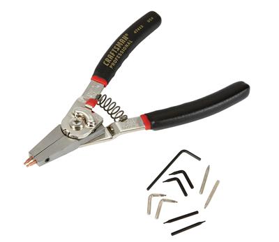
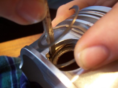
Snap rings or Tru Arc retainers require special pliers for installation. Just insert the tabs on the pliers into the holes on each end of the retainer, apply pressure to the pliers to compress the retainer, then install in the groove.
Snap Rings

Generally Tru Arcs are the easiest to install and are more popular in lighter duty applications. The snap ring or Tru Arc is easily installed using dedicated pliers. The tips of these pliers fit into the holes at the ends of the snap ring. When the pliers handles are squeezed, the snap ring compresses enough to firmly seat into the retaining groove on the piston. A word of caution: snap rings are manufactured with a smooth and rough side. Be sure the smooth side faces the wrist pin. Also, install the snap ring with the open end pointing down.


The Lock-in tool is designed to install Spirolocks with minimal handling of the wire. The tool has different heads dedicated for specific wrist-pin sizes. The first step is wrapping the Spirolocks around the groove and positioning the end on the index mark.
Spirolocks

The Spirolocks—sometimes referred to simply as a spiral retaining ring—are constructed of flat stainless-steel wire wound into a spiral or small coil. They’re very effective at securing the wrist pins; but when stretched out for installation their sharp edges are exposed. “Spirolocks are the cheapest but are difficult to install and disassemble,” says Stevenson.

Many pistons require two Spirolocks on each side, doubling the installation time. There are probably as many different ways to install Spirolocks as there are engine builders. Using jewelers’ screwdrivers to dental tools, experienced mechanics have developed a number of personal tricks to avoid sliced skin as well as speed up the installation process. There are also some dedicated spirolock tools.


Once the leading edge is inside the groove, the tool is turned counterclockwise to install the lock on the first side of the piston. Lock-in also has tool heads for dedicated sizes to help install circlips.
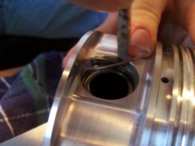
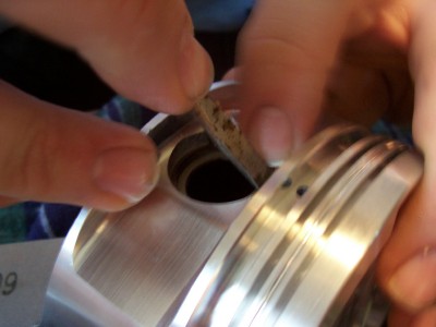
A Spirolock is installed by spreading it apart slightly. A leading edge is positioned inside the piston’s retention groove, then the coils are literally spun or walked into place inside the groove. Some engine builders prefer using their fingers, but most use one or two small flat-head screwdrivers to massage the spiral wire into the retention groove.

There are also dedicated tools such as the Lock-in tool from Precision Engine Service. It’s designed to install a Spirolock without having to handle the sharp edges. The Spirolock does have to be spread apart to fit in the grooves of the tool. The tool is positioned in the piston to start the leading edge of the Spirolock into the retention groove. The tool is then rotated counterclockwise until the Spirolock is properly seated in the groove.


The snap ring and Spirolocks must be used with wrist pins that have a flat face and the appropriate retaining groove in the piston pin boss. The circlip uses a wrist pin with a chamfered edge, right, and also must be used in the correct groove.
Pins Designed For Lock Types


Although the three different types of wrist-pin locks are not meant to be interchangeable, the retention grooves machined for Spirolocks and snap rings are similar. Tru Arcs, or snap rings, and Spirolocks must also be used with wrist pins that have flat edges.

“The grooves are different shapes and dimensions, however Tru Arcs can be used interchangeably with Spirolocks of the same thickness,” says Stevenson.

Circlips, however, must be used with chamfered wrist pins. The retention grooves on the pin bosses must be designed with a small relief machined on the edge of the groove. Sometimes this relief or notch is used to help facilitate removal. Or it can be used to properly position a certain design of wire clip.

Tips and tricks for wrist-pin locks

  • Regardless of the type of lock, make sure they’re properly seated and flush all the way around the retaining groove.
  • Avoid scratching the piston with screwdrivers, O-ring picks or other tools. A deep ding can lead to a stress riser.
  • Make sure the retaining groove is clean and free of grit that can prevent a proper fit.
  • Some engine builders will deburr the ends of wire clips to ensure a cleaner seat in the retention groove.
  • Make sure the pistons and rods are properly oriented before installing the pins. You don’t want to pull them apart because the rod chamfer doesn’t face the crankshaft fillet radius when the piston assembly is installed into the cylinder.
  • Regardless of the style, wrist-pin locks are inexpensive, so the best policy is to never reuse them.
Getting Right with Wire Locks

“Wire locks are the best overall solution from a reliability standpoint as any side-to-side forces exerted by the pin serve to further seat the lock into its groove,” says Stevenson.

Wire locks are by far the most common lock type for high-performance pistons and come in three popular styles for automotive use (there are more that can be found in industrial and motorcycle engines). There’s the basic open-end clip that resembles a “C.” This lock can be installed with bare fingers or a mix of screwdrivers and picks, depending on the whims of the engine builder.


To assemble a full-floating piston and rod combo, first install one of the locks. Next, lube the connecting rod's bushing and insert the wrist pin. The final step is installing the lock on the opposite side.
A modified version of the wire clip has up-swept tangs on each end that have a similar function as the holes on a snap ring. This allows a dedicated pliers for installation. This style is more popular with OEM applications than performance engines.

Engine builders generally develop a favorite style of wrist-pin lock over years of experience. Again, the two most popular with performance engines are the Spirolocks and wire clip or circlip. There is no research or data indicating that one is stronger or better designed than the other. It basically comes down to a choice by the engine builder. However, the piston manufacturer must be informed of this choice because the retention groove is machined differently and the correct wrist pin must be used.
 
Last edited:
When to Upgrade Wrist Pins

001-diamond-pistons-when-to-upgrade-pins.jpg

Like rod bolts, wrist pins are the Kryptonite assassins of careless race engine assembly. Trend Performance offers endless solutions to engine longevity with wrist pins of every conceivable size, wall thickness and material.

It has been said that the piston and connecting rod are the most tortured parts in a performance engine. Few engine builders dispute that notion, but what about the less glamorous piece of steel that mates them together through thick and thin? In a sense, the wrist pin is like the unsung soldier who throws himself across the barbed wire barrier while the rest of the troops run across his back. Stroke for stroke, the wrist pin takes one for the team every bit as much as the rod or the piston. If you’re using high-level forced induction, nitrous oxide injection, high rpm or heavy sustained loading on your performance engine, upgraded wrist pins represent the insurance deal of the century.

The wrist pin is charged with the daunting task of snatching the piston back from the brink of disaster hundreds of times per second in the face of massive cylinder pressure and alternating loading that can approach 400 g’s. Under these conditions, the pin can bend and distort to an egg shape even if it is well lubricated. The worst case occurs when the piston reverses direction at the top of the exhaust stroke. There is little or no cylinder pressure to cushion the reversal, so the pin bears the full weight of the high-speed piston as it is yanked back down the cylinder. On the intake stroke the piston reverses against rising cylinder pressure that typically peaks around twelve degrees after top dead center (TDC). Here, the inertia loading is also substantial, but it is cushioned by the force of the combustion event.

002-diamond-pistons-when-to-upgrade-pins.jpg

Wall thickness is a critical factor based on application. Upgrading to a thicker wall pin with better material is always a positive step in any racing or performance engine build.
It would be difficult to overstate the importance of the wrist pin in any high-rpm or high-power environment. In some normally aspirated applications seeking maximum compression ratio, many builders push the piston to head clearance right up to the point of leaving very slight witness marks on the piston crowns. Hanging on to the piston at very high piston speeds and tight clearances becomes crucial to engine survival. In other cases, high cylinder pressures via nitrous or forced induction attempts to bend and deform the wrist pin. When the pin bends, it tries to force the lubricant out of the way and friction increases. More power is consumed, and the associated heat tries to destroy the pins, pistons, and connecting rods.

What’s the Best Wall Thickness?

Armed with this knowledge we must ask what factors influence pin choice and what power levels or applications call for increased wall thickness, better materials and/or special coatings? More power always equals more cylinder pressure, so we are obliged to consider parts that complement the engine’s power level. As a rule, most off-the-shelf performance pistons are supplied with appropriately sized pins for the intended application. Of course, racers often abuse that with the addition of power adders that can easily increasing pin loading beyond what standard pins can tolerate.

As with everything in racing and many high-performance street engines, pin choice is application specific. Your piston supplier won’t provide something that is not up to the job, but you must be honest with yourself about your intentions. In a racing environment, tool steel wrist pins with a .090-.125-inch wall thickness are often adequate for most normally aspirated applications, but big block engines exceeding 800-1000 horsepower, need pins with a minimum .150-inch wall thickness because they are slinging around heavier pistons. And if you are running high boost or nitrous oxide, the pins must be compatibly thicker and of top grade material. Wrist pin deflection, insufficient pin clearance or poor lubrication all combine to magnify the detrimental effects of an inadequate pin selection.

003-diamond-pistons-when-to-upgrade-pins.jpg

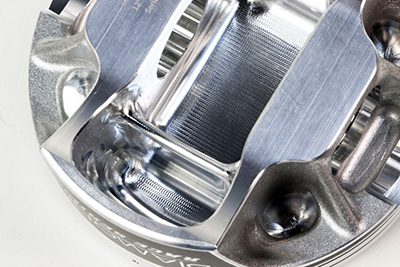
Often, a racing piston will incorporate a forged side relief design. This moves the pin bosses from the outside of the piston inward, shortening the wrist pin to reduce mass. However, it can place additional load on the wrist pin, requiring a stronger base material or thicker-wall pin.
Here’s a handy ballpark chart you can use for preliminary wrist pin selection before you talk to the techs about your exact requirements.
Normally aspirated
Stock pins 450-500HP
.090-.125 500-700HP

* If you are street supercharging or using a mild NOS shot its good practice to step up a bit more from the recommended normally aspirated pin sizes

Supercharged or NOS
.130-.150 700-1000HP (H13 and DLC recommended)
.160-.250 1000-1500HP (H13 and DLC recommended)
.260-.330 1500HP-plus (M2 or TP1 and DLC recommended)

According to Steve Rhodey at Trend Performance, “The wall thickness is subject to change upon more info obtained at the time of tech. A lot of wall thicknesses will overlap and that’s ok. It’s all about getting the right part. A lot of people have it in their heads that pins only dictate rotational mass, but that’s not always the case considering the loading a wrist pin can see. There won’t be ANY mass to worry about if the pin is too light.”

004-diamond-pistons-when-to-upgrade-pins.jpg

Trend Performance high-tech wrist pins are offered in all popular sizes according to length, wall thickness, material and available DLC (Diamond Like Carbon) coatings for superior performance.
Among other things to discuss with your tech rep, pin clearance and lubrication quality rank high. Any application powerful enough to flex the pin will benefit from loosening up the pin clearances. Most pins run with a clearance of 0.0008-0.0010-inch. For severe usage and big cylinder pressure, you can avoid trouble by opening the pin clearance to 0.0020-0.0022-inch. Tight clearances are often a disaster waiting to happen. Looser is almost always safer, particularly if there are also lubrication issues.

Typical wet sump systems offer plenty of oil splash to help lubricate the pins. In a racing application, you often have dry sump lubrication, a crank scraper, a pan kickout and a vacuum pump to dramatically reduce oil in the pan and available splash lubrication. Windage and the oil fog can be over-controlled in some cases. Some builders even report greater signs of pin distress on the side of the engine with the crank scraper and pan kickout because they are so effective at stripping away the oil on that side of the engine. Extra clearance always helps in this environment.
In almost every high-pressure environment, tool steel pins, DLC coatings, looser clearances and sufficient lubrication are the insurance you need. Trend Performance addresses these needs with a full range of pin selections to cover every possible environment.

005-diamond-pistons-when-to-upgrade-pins-271x300.png

Diesel engines and high cylinder pressure environments such as Top fuel and Funny Car engine require thick wall tool steel pins to take the severe pounding dished out by high boost levels and nitro-methane fuels.
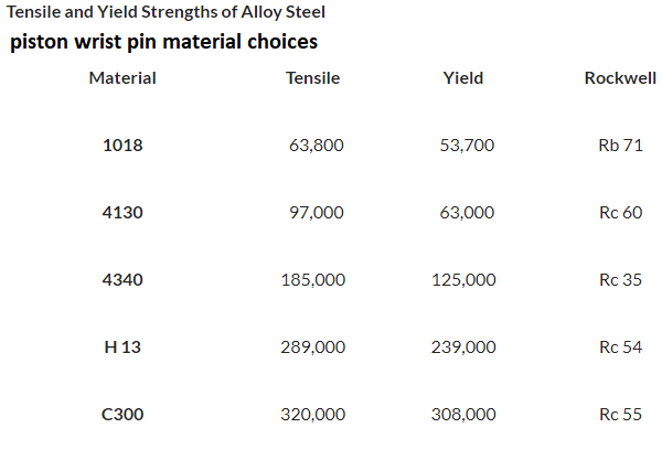
Beginning with Trend’s G-Series, pins are produced from chrome molybdenum 4130 thick-wall solid stock, a popular choice with, piston manufacturers, and shelf-stock piston sellers due to better material and precision machining. 4130 alloys are superior to the common 1018 mild steel alternative. This steel pin is ideally suited for use in naturally aspirated race engines. Pins are heat treated (60 Rockwell O.D./45 core), tumbled, and ground to 0.125 and 0.155 wall selections.

Trend uses H13 tool steel for most of its premium piston pins. H13 is considered the best all-round material for most applications, especially in power-adder engines; it is also a popular choice in Pro Stock drag racing engines. H13 pins have a Rockwell hardness value around Rc54 and easily accept a DLC (Diamond-Like Carbon) coating. These pins are offered for all popular applications in 0.005-.0.010inch wall thickness increments from 0.135-inch to 0.225-inch and 0.225, 0.250, 0.275 and 0.300-inch walls for severe applications. H-13 pins are also ID honed for stress relieving and hard turned ends and chamfers can be added if required.

006-diamond-pistons-when-to-upgrade-pins.jpg

In addition to optimum wall thickness, tough finishes like Trends DLC coating are highly desirable to preserve engine parts when stressed with heavy pounding, insufficient lubrication and tight clearances, all problems that Trend has handily solved.
TP1

A new Trend pin alloy, TP1 is exceptionally hard and very tough. It is coated and less expensive than its rival, C300 maraging steel and it is specified exclusively for Top Fuel, Funny Car, and Pro Stock engines. These new pins are currently available in custom sizes or stocking sizes of 0.270, 0.310 and 0.330-inch. This material is becoming very popular in the high hp sport compact world, pro mod, Radial, sportsmen, arenas. even a lot of limited late model, super late model, outlaw and sprint cars are running it for its ability to be put through hell and stay round.

Top Fuel and Funny Car teams typically run their pins until they bend, which is almost immediately. They don’t coat their pins because it adds expense to disposable components.

007-diamond-pistons-when-to-upgrade-pins.jpg

In compliment to wrist pin material, diameter, and wall thickness, retention style must also be considered. These Diamond Rebel series pistons utilize pin buttons which insure that even under the most aggressive racing conditions, the wrist pin cannot become dislodged.
Trend believes its new coated TP-1 pin possesses far superior longevity and the ability to resist galling and extreme bending moments. It is heat treated to a through-hardness of Rc60 (hardened from it outer case to its inner core), This pin combines the toughness of the maraging steels and the hardness, compressive strength, and surface qualities of M2, the superior high-speed tool steel.
In terms of tensile strength and yield strength, H13 pins and the newer M2 and TP1 pins are well beyond more common 4130 and 4340 alloys, but they are applications specific. It’s vital that you talk with Trend’s experienced techs to help you “pinpoint” the pin you need for your engine. There is really no environment too tough for Trend Performance wrist pins, but you gain the greatest benefits by upgrading to the proper size and level of prep. A little bit thicker walls with looser clearances and good lubrication can ensure that all the combustion pressure you generate is used to turn the crank and not merely drive the piston down the rod when a pin fails. Don’t overlook this critical step in your build sheet selections.

This article was sponsored by Diamond Pistons. For more information, please visit our website at www.diamondracing.net


0
 
A Good Read Today Grumpy.
A very good chance I am going to Nitrous Boost. Emergency Power.
I never had piston pin wrist pin issues & I do not want them.

Build for just in case 1000+ HP.

I am going with Diamonds pistons.
I do not want a lightweight design.
Connecting rods are Crower Titanium. Plenty of Reciproctating weight reduction.
 
Kwr1wyM.png


I notice Diamond Pistons has on the shelf pistons for a Pontiac V8 Grumpy.
Popular stock engine parameter 400 & 455 then along with the Stroker engine combos.
Made from 4032 Alloy & listed in the Race engine piston section of the Catalog.
They give the 4032 Alloy a 650 HP Rating for Pontiac V8, Olds V8, Small Block Chevy, And Big Block Chevy along with Chysler Mopar 383-440-426.

Just a small shot of Giggle gas & I will exceed the 650 HP rating of 4032 easy.
Till last night I have never ever seen a Piston manufacture rate their pistons by HP.

Looking at One off custom made 2618 alloy Diamond pistons.

Some tradeoffs as we both know.

How long have you seen 2618 Pistons last yourself Grumpy ?
I expect 10,000 miles life expectency from my own Raced driven hard non stop with 100-500 mile oil changes & valveslash checked - adjusted also then too.
Nearly all HPC piston coatings I have seen do wear off pretty quick.
 
Speed talk I am reading.
One Guy got 70,000 miles out of his 2618 Alloy Pistons.
Decided to teardown and inspect.

Porsche used 2618 Alloy Pistons stock.
 
Just For future Reference for all The Chevy Guys Here.
I am a Pontiac V8 Guy & a Chevy & Olds V8 guy.
SPENT THE LAST FEW HOURS RESEARCHING.

YOU DO NOT WANT TO USE 4032 ALLOY PISTONS IN HIGH HORSEPOWER APPLICATIONS.
MAX HP IS 650 WITH 4032 & THAT IS PUSHING IT.
BE IT NORMAL ASPIRATED, NITROUS OXIDE, ROOTS SUPER CHARGER, CENTRIFUGAL SUPERCHARGER, & TURBO CHARGED.

ONLY 2618 ALLOY PISTONS SHOULD BE USED FOR 700 + HP.

BITING THE BULLET TO PAY $$$$.
NO SAFE CHOICE BUT TO DO IT.
 
Grumpy..... I joined this forum because of your piston pin posts.... I am well read in pins because of you and I assure you these are from the supplier you got the photos from.... I however will not be doing business with them again and next time will do it my self due to some less than honest pricing. I had the pins reworked by the local machinist... Same (#@$%@#) that broke my piston ring and caused me to have to buy a scale and do some questionable piston lightening techniques to get them back in balance. Everything is now sitting in the car awaiting wiring, sensors and oil and cooling lines. I thank you. I wouldnt have dared order a custom specialty pin if I had not read your articles in detail.
 
Back
Top