Port Matching Procedure (Step-by-Step Guide with Pictures)

Indycars

Administrator
Staff member

Tools and Equipment:


Make fixture with 1/16", 3/32"** and 1/8" holes in a 3/4" x 2" x 2" steel block
    • Drill Bits: 1/16", 3/32", 7/64", 1/8", #36, #37, #38 and #39
    • 3/32" Roll Pins, 1/2" Long
    • 1/8" Roll Pins, 1/2" Long
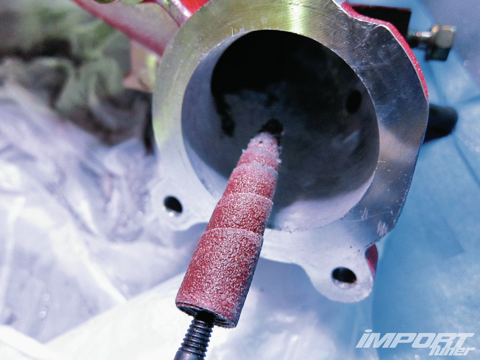
    • Grinder and/or Dremel Tool (Dremel Tool in not required, but does make it easier)
    • Scribe
    • Dykem or Sharpie Pen
    • Drill Motor
    • Leather Punch
    • Intake Manifold Gaskets
    • Heads
    • Head Gaskets
    • Engine Block
    • Eye Loupe (8x Power) (Optional)
    • Dial Calipers
    • C-Clamps
    • 1/2" Counter Sink Bit
    • 4 : 3/8-16 x 1" Bolts, Nuts and Flat Washers (Or the correct size for your setup)

Planning Stage

Before you ever start, work thru the complete process in your mind while putting parts together and taking them apart, just like you were actually doing the work. You'll want to find any snafus now while you can easily do something about them. I did this with my brother, which is even better when you have another point of view and lots of questions.

After looking at the manifold and head I decided to place the hole above the 2nd bolt in from each end. You will want to consider such things as the water jackets and how deep can you drill a blind hole. The hole in the head must be a BLIND hole.

Using the leather punch put a hole in an old gasket or similar material to check for a snug fit on the 3/32" roll pin.

** Normally when drilling a hole for a roll pin, you would use the same size drill, but that made it too hard to remove the roll pin during times throughout this procedure it will need to be extracted. Test drill some aluminum to check for fit of the 3/32" roll pin. I found that a little larger hole worked better, I used a #38(0.1015") drill bit. This is the size you will use for one of the holes in your fixture.


Image00_PortMatchingFixture01.jpg

Download the PDF file for the fixture at the bottom of this post.

If you are planning on decking the block or milling the heads, it would be better if done before you start this port matching procedure. Of course it all depends on just how much material you will be removing. If it's only 0.010 or 0.015", then it's not going to make much difference. But if you are planning on taking a lot more it might be worth considering doing it first.


Procedures

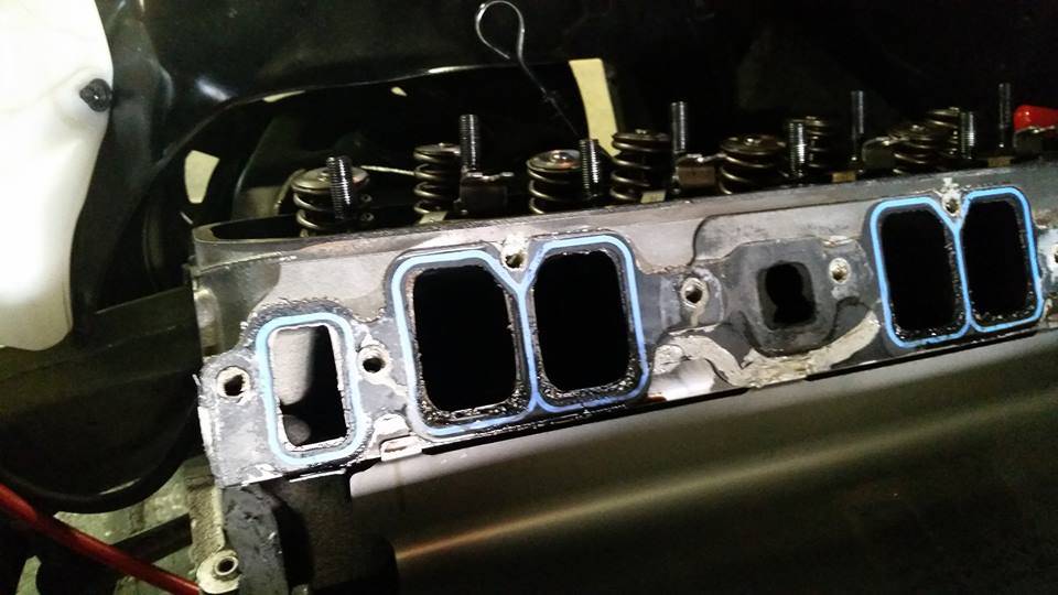
Align the gasket to the ports in the head, then using the 2-4 bolts/flat washers lightly tighten them to hold gasket in position.
You don't want the gasket moving while you are working to setup and drill the initial 1/16" holes. The alignment will be subjective, just pick the best fit you can find. In my situation, the head was slightly bigger in some areas than the gasket. Therefore I won't be doing any grinding on the ports in the head. The grinding marks you see in the picture is only some clean-up I did previously.


Image01_GasketOnHead0933.jpg

Insert the 1/16" drill in to the fixture and place in position where you will drill blind holes in the head.
You may need to use the C-Clamps here to hold the fixture in place if it will fit, or get some help from a buddy. It's going to be very important that the hole be perpendicular to the head surface. Drill only enough to go thru the gasket and mark the head, maybe about 1/32" deep in the head. Move to the other end of the gasket/head and repeat.


Image02_DrillLocationOnHead0937.jpg

Remove the gaskets and label as to which side it belongs, odd or even cylinder head.

Set the depth, to drill 1/16" hole in head.
Since the fixture is 3/4" thick and I want to drill a 1/4" into the head, the drill will need to extend out of the drill 1". It's best to also measure the distance the drill extends past the fixture once it's inserted as a way to confirm. You sure don't want a mistake here.


Image03_DrillDepth1001.jpg

Image04_DrillDepthConfirm0997.jpg

Continue to drill to the desired depth using the fixture. Make sure you have indexed the drill into hole.

Change to the 3/32" drill bit or the alternative size you decided on. Setup your depth again and drill to final size.
For me the final size was made with a #38 drill bit.

Using the leather punch, center on the 1/16" you drilled in the intake gasket and punch to size.


Image05_PunchHoleInGasket1036.jpg

Using the dial caliper measure the actual depth of each hole in the head.


Image06_MeasureHoleDepth1018.jpg


Important Note: It will be very hard to remove a roll pin that's too short, since there will be very little to get a hold of. I know, it took me about an hour to remove one that was too short.


Cut and/or grind roll pins to length.
They need to extend above the intake manifold gasket about 0.005" to 0.010". Since my FelPro 1206 gaskets were 0.065" thick, then the roll pins need to extend out of the head 0.070" to 0.075". It's much better to start with one that you think is 0.020" too long, then install it and measure how far it sticks out of the head. Roll pins are cheap, don't be afraid to throw one away and start again if you get it too short.


Image07_MeasureRollPinLength1012.jpg
Image08_GrindRollPin1015.jpg

With all four roll pins installed, check for height.
Be certain that you have them installed so that they are fully seated in the hole. The closer the roll pins are to extending out of the head the same distance, the better. Try to keep the difference from longest to shortest to less than 0.015".


Image09_RollPinHeight1030.jpg

With roll pins installed, position intake manifold gasket over the roll pins.
Inspect the alignment of the gaskets. Do they match the head as you intended.


Image10_CheckGasketAlignment0933.jpg

Make small adjustment to intake gasket position if necessary.
Using the 1/16" drill bit elongate the hole so that you can move the gasket into the correct position. Then using a pin punch tap around the other side of the gasket hole, closing the gap around the roll pin and making it tight again. This has it's limits of course, maybe 0.010" to 0.015".


Image11_PinPunchMarks0940.jpg

Repeat the above steps for the other head.

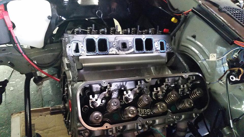
Install the heads onto the block with roll pins in position.
Using the appropriate head gaskets, install the heads, using 2-4 head bolts per head and tighten to 20-30 ft lbs.

Install the intake manifold, with intake gaskets placed into position over roll pins.
You don"t have to install the intake gaskets, since the manifold is really only resting on the roll pins. It's your choice on this step.

Install all intake manifold bolts and finger tighten.

Check the end rail gaps for consistency, side to side.
Using a feeler gauge, check to see if the gap is consistent between cylinders 1-2 and 7-8. Don't expect it to be perfect, but it should be close enough that you can't visually see any difference.


Image12_EndRailGap0956.jpg

Lightly tighten the manifold bolts, starting with those associated with the larger end rail gaps.
Work around the manifold several times checking and making sure all bolts are snug.


Image13_TightenManifold0953.jpg

Using a block of wood, place it against the manifold directly over the roll pin locations and tap with about a 2 lb hammer. This should leave a nicely visible impression of the roll pins location on the intake manifold gasket surface. Problem is you won't know for sure until you take the manifold off and look.

Remove the intake manifold and inspect for roll pin impressions.


Image14_RollPinImpressionIntake0964.jpg

Center punch the roll pin impression in the manifold to prepare for drilling a 1/16" pilot hole.
I removed the Point from my Scribe and made sure the point was fairly sharp. This would only work if you are working on an aluminum manifold.


Image15_CenterPunchImpression0968.jpg
Image16_CenterPunchedImpression0972.jpg

Using the fixture, drill a 1/16" hole completely thru the manifold.

Using the fixture, drill the hole to size in the manifold, same size as the head.
Roll pin should just fit snug. Repeat for all 4 holes. Later these holes will be enlarged to make final assembly possible.

Using Dykem or Sharpie pen, paint around all 8 ports on the intake manifold.
I used the Dykem, but the Sharpie would have worked better for me. The Dykem was too thick and flaked a little, instead of leaving a very well defined line.


Image17_DykemAroundManifoldPorts0976.jpg

Install two roll pins in intake manifold and then place the gasket over the roll pins.
You can use any length of roll pin for the intake manifold. Make sure you have the right gasket for each side of the manifold. You did label them in the step above?

Install the four 3/8" bolts and washers to hold the gasket in place.
Using a wrench, just barely snug bolts. It's only to keep the gasket from moving around in the next step.


Image18_ScribePortsOnIntakeManifold0948.jpg

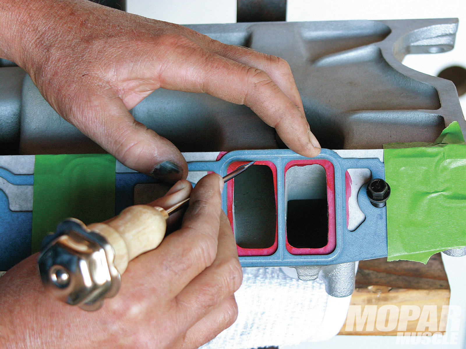
Scribe lines around in the inside of the gasket for the intake ports.
Be careful and support the gasket with your fingers, when scribing along the very thin section between two intake ports.

Repeat the last 3 steps for the other side of the intake manifold.

When ALL grinding is done, then drill the intake manifold holes to 1/8" and chamfer from the gasket side to make final assembly possible.
Slightly bevel the underside of the intake flange mating surface to about double the roll pins diameter. The intake manifold should easily seat over and tends to self align on the roll pins as the manifold is installed on the engine.

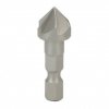
Image19_CounterSinkManifold.jpg
Image20_CounterSinkBit.jpg


There you have it, I will leave the grinding procedures to someday when I will get around to it. Hope this helps if you are so inclined to go this route to match your ports!

Please if you read something that does not make since or if I just left out a word, let me know so I can make corrections.


.
.
.
.
 

Attachments

  • PortMatchingFixture01.pdf
    90.1 KB · Views: 60
Last edited:
Re: Port Matching Procedure (Step-by-Step Guide with Picture

WOW!
as always IM VERY impressed with both your camera skills and YOUR MECHANICAL & FABRICATION SKILLS , so FEW people take the time to think things thru and even FEWER actually do the detail work, with anywhere near the attention to detail you've obviously taken!
I could and have done similar work on engines but I,ve never got even close to your photographic skill level
viewtopic.php?f=52&t=8460&p=29682#p29682

http://gottafishcarburetors.com/CFM Formula.html

http://wallaceracing.com/intakecfm.php

https://www.summitracing.com/parts/...Hci_rngCjPIi0Hzl27DmoGKgPl5jkEzRoCXYoQAvD_BwE

use of a gasket sealer that helps prevent gasket movement helps
edl-9300.jpg

Felpro-Gasket-Port-Sizes.jpg

vgd5.jpg

IDEAL


PortMatch03.jpg

ACCEPTABLE BUT LESS THAN IDEAL


PortMatch02.jpg

LEAST FAVORABLE CONFIG
 
Last edited by a moderator:
Re: Port Matching Procedure (Step-by-Step Guide with Picture


Golly..... now you are making me blush. :oops:

I've read the text so many times now, that I can only see what's in my head, not what's on the page. Surely there is something that's not quite clear or just wrong, that needs to be changed, if anyone has a question or comments, please do so !
 
Re: Port Matching Procedure (Step-by-Step Guide with Picture

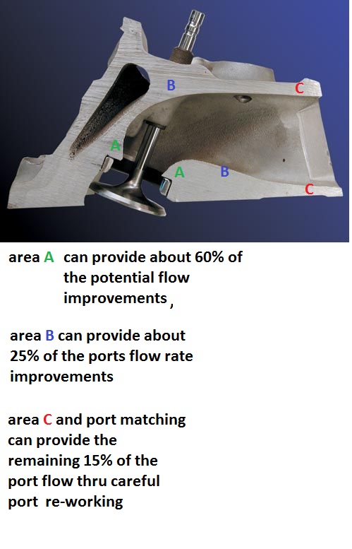
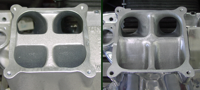
many guys spend 90% of there porting time on intakes matching the ports to the heads and opening the runners up, but a surprising amount of the potential flow improvement on many intakes involves the port work on the runner entrances in the plenum area.
plen1.JPG

plen2.JPG

plen3.JPG

plen4.JPG

plen5.JPG

plen6.JPG
 
Re: Port Matching Procedure (Step-by-Step Guide with Picture

tramp3.JPG

obviously you will need to carefully port match some intakes to some head ports due to the wide variation in sizes and shapes
http://www.carbideselect.com/burshpescuts.php
p15831aa0_image_large.jpg

vgd4.jpg

you can add a bit of chamber volume and reduce the potential hot spots that help cause detonation by opening and blending and smoothing the combustion chamber
00936.JPG

00935.JPG

(1) open throat to 85%-90% of valve size
(2)cut a 4 angle seat with 45 degree angle .065-.075 wide where the valve seats and about .100 at 60 degrees below and a .030 wide 30 degree cut above and a 20 degree cut above that rolled and blended into the combustion chamber
(3)blend the spark plug boss slightly and lay back the combustion chamber walls near the valves
(4)narrow but dont shorten the valve guide
(5) open and straiten and blend the upper two port corner edges along the port roof
(6) gasket match to/with intake and raise the port roof slightly
(7) back cut valves at 30 degrees
(8) polish valve face and round outer edges slightly
(9)polish combustion chamber surface and blend edges slightly
(10) remove and smooth away all casting flash , keep the floor of the port slightly rough but the roof and walls smoothed but not polished.
(11) use a head gasket to see the max you can open the combustion chamber walls
(12) blend but don,t grind away the short side radius
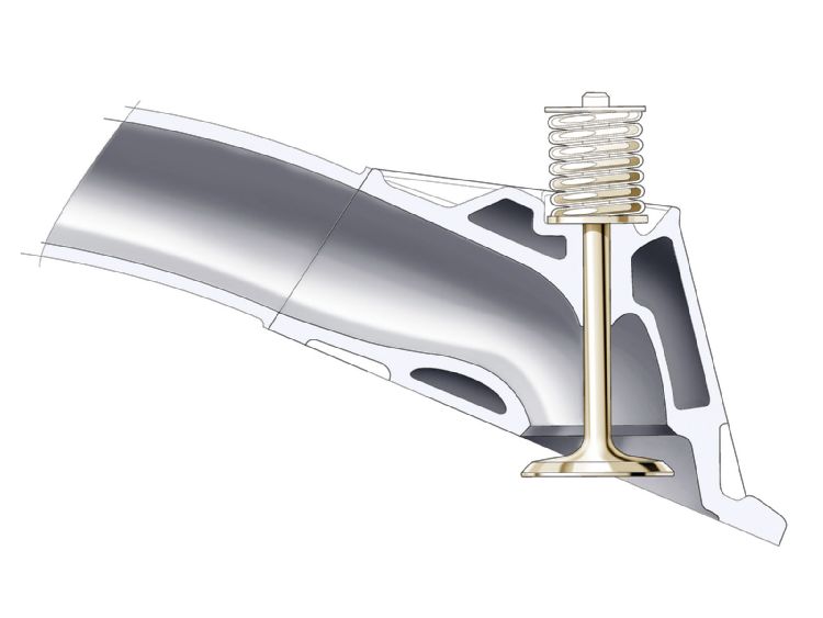
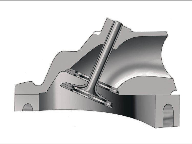
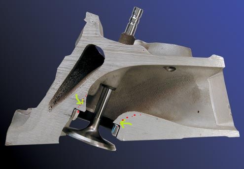
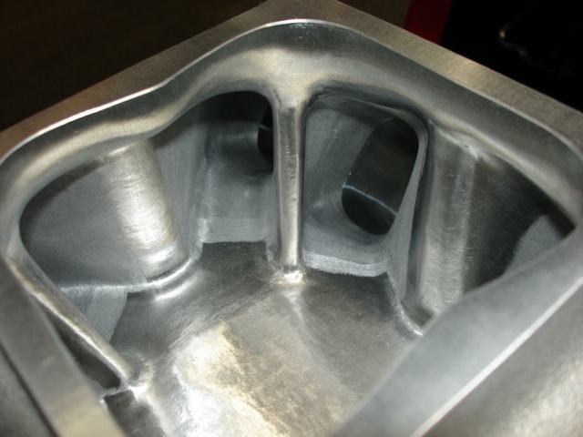
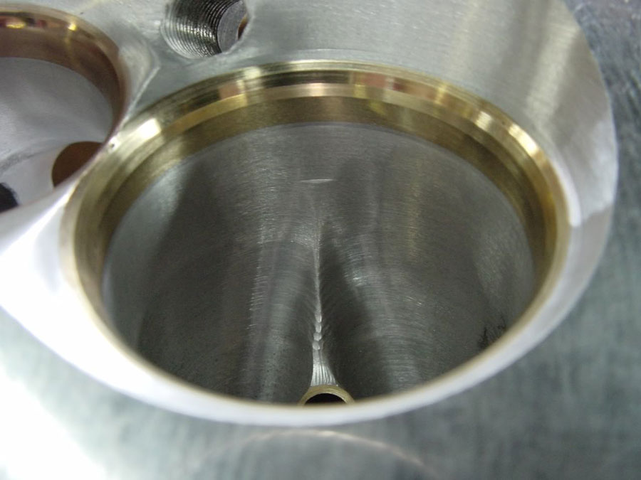
notice how the valve seat supporting casting in the cylinder head, throat extends out into the port and restricts the valve flow, a critical area that port and bowl clean -up can usually gain significant flow improvements
p158310_image_largea.jpg


portmatchprocomp1.jpg


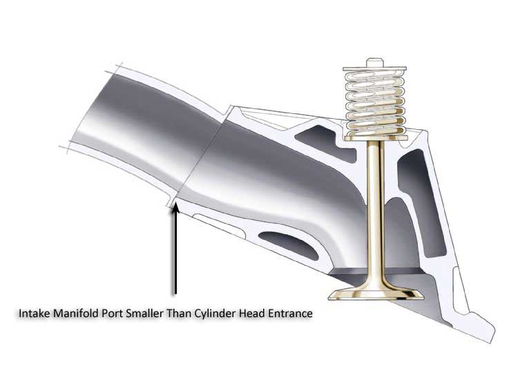
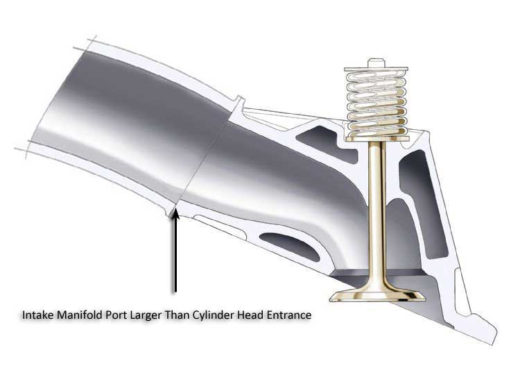
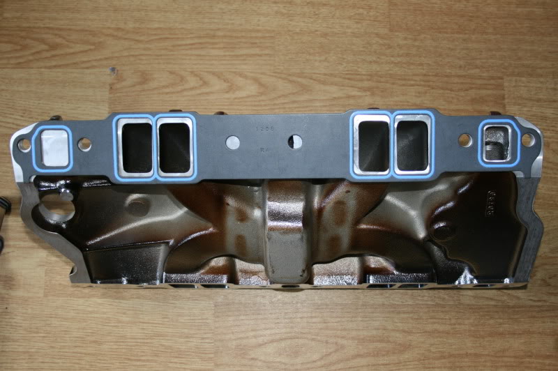
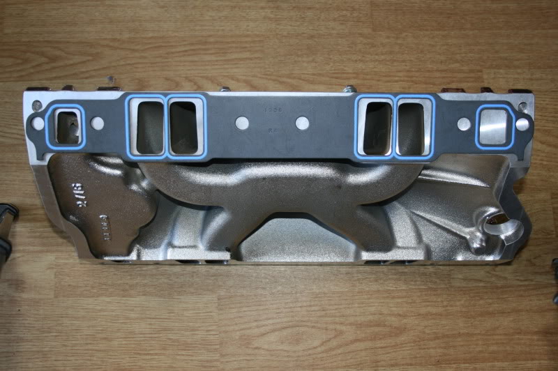
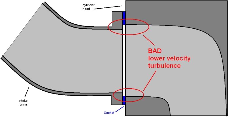
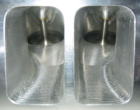
Heres a 1206 gasket on a VORTEC style edelbrock aluminum intake showing the port size and location where its rather obvious that at least minor port matching would also help, notice the intake runner exits are significantly smaller and taller than the heads runner entrance size, and the shape of the intake ports, and theres more aluminum, port wall and flange thickness available for sealing the intake gasket if ported extensively, this is frequently a limitation to how extensive the intake runner can be ported on some intake designs,
its the guys that take the time and effort to notice the differences and correct the miss matched areas that will consistently get better results,
RATHER than the guys who open the package,they get as it came out of the UPS truck or off the speed shop counter, and just assemble the components , just assuming it will fit and function correctly

portmatchprocomp2.jpg


tunnela4.jpg


BEFORE PORT/RUNNER CLEAN UP
>>>>>>>>>>>>>>>>>>>>>>>>>>>>AFTER PORT/RUNNER CLEAN UP AND PORTING


Ive always been amazed at the number of guys who take an intake manifold out of the box and proceed to bolt it on an engine with out doing the port matching and plenum smoothing and runner entrances mods required to maximize flow rates and even out fuel/air distribution issues and reduce air flow turbulence issues, its common to be able to gain 15-20 horse power if you take the time to do whats required.

as with all new intakes ,closely inspect it for loose machining chips or casting flaws, and use a MATCHING SIZE intake gasket to judge both its port location and size in relation to your matching cylinder heads, port matching may be an option if theres a noticeable difference, don,t be afraid to get it cleaned up and carefully matched ,but obviously don,t go crazy removing metal,it should be close to the way it needs to be right out of the packaging


lets do a bit of math
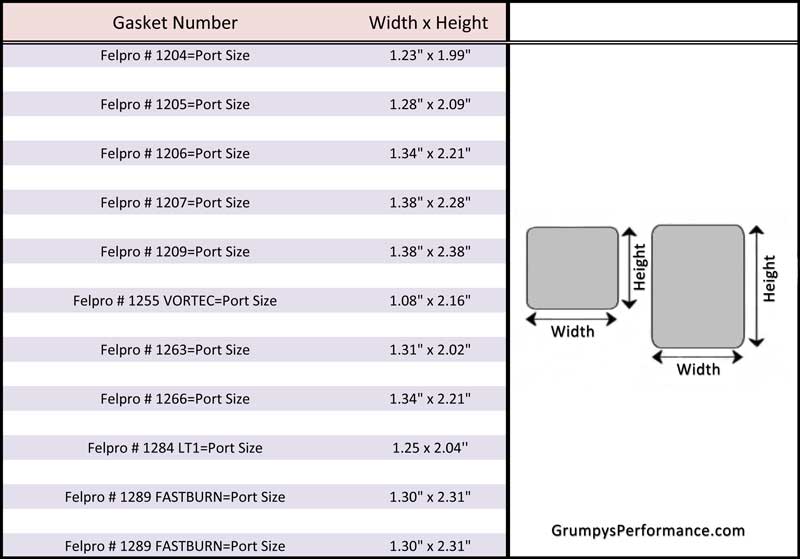
just a bit of info on intake gaskets sizes to match port cross sectional areas
volumetric.gif

116_0403_basic_10_z.jpg

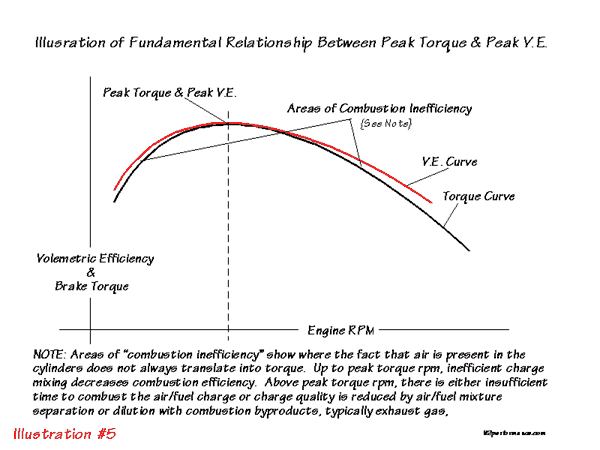
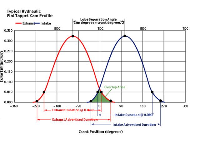
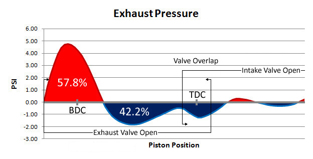
a significant improvement in cylinder fill efficiency can be had by allowing the exhaust scavenging to draw the following intake runner charge of fuel/air into the cylinder and flush out the proceeding, charges burnt gases, but it requires matched cam timing and a low restriction exhaust , properly matched headers to function.
exhaustpressure.jpg

EXFLOWZ4.jpg


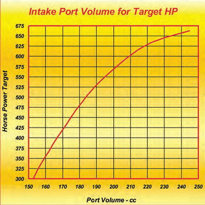
USE THE CALCULATORS below to find the approximate intended power band the port cross sectional area will allow, that way you won,t be tempted to think its some other factor when you find the combos power curve limitations, but remember properly matched exhaust scavenging and cam timing potentially extends and broadens that potential power curve[/color][/size][/b]
http://www.rbracing-rsr.com/runnertorquecalc.html
http://www.wallaceracing.com/chokepoint.php
http://www.wallaceracing.com/header_length.php
yeah! MANY INTAKES ARE PURPOSELY UNDER SIZE TO ALLOW ACCURATE PORT MATCHING,
the problem is that many don,t have enough aluminum material in the runner wall thickness to allow you to fully match some heads port sizes
I recently ran across a couple posted photos of a guys BBC engine that was having issues burning oil,
if you look closely the pictures are rather useful in diagnosing the issues source.
if you look at the intake ports youll notice the lower 2/3rds show visual indications,
of oil flow contamination while the upper 1/3rd shows far less staining,
if the oil flow was coming from leaking valve guides , and spread through the runners during the valve over lap,
where the air flow may momentarily reverse direction in the plenum and runners at lower rpms, the oil stains,
would tend to be more uniformly spread, but the darker stains in the lower runners points more strongly,\
at the lower edge of the intake gasket that prevents oil from the lifter gallery are not fully sealing, it is very common if the heads have been milled
(ESPECIALLY ANGLE MILLED) or the person using the intake gasket used extra thick intake gasket oil seals.
this is one reason many guys prefer to dimple the under side of the intake manifold and block china wall mating surfaces,
and simply apply a bead of silicone gasket sealant to both adjacent mated surfaces then install the intake manifold,
with a thick intake gasket and a thin 1/8" bead of sealant around the ports and coolant passages

bbcrt1.jpg


notice the upper intake runner walls have far less oil stains, and the oil flow flowing over the hot intake valve back surface,
this un-wanted oil flow leak, rapidly forms a burnt ash coating,
that can and does reduce air flow and cylinder fill efficiency.

bbcrt2.jpg


I also have to point out the intake runners in the heads are not port matched to the intake gasket,
this, and not matching the matched intake runner exits to the intake gaskets,
is generally going to cost you a measurable loss in potential extra air flow at peak rpms

bbcrt3.jpg

http://garage.grumpysperformance.com/index.php?threads/carb-intake-test.58/


http://garage.grumpysperformance.co...olishing-combustion-chambers.2630/#post-50247

http://garage.grumpysperformance.co...ing-tools-abrasives-sources.10683/#post-46209

http://garage.grumpysperformance.com/index.php?threads/porting-can-help.462/page-3#post-45238

http://garage.grumpysperformance.co...u-buy-bare-or-assembled-heads.534/#post-41293

http://garage.grumpysperformance.com/index.php?threads/port-speeds-and-area.333/#post-37705

COMMON SBC INTAKE PORTS
felpro # 1204=Port Size: 1.23" x 1.99"=2.448 sq inches

felpro # 1205=Port Size: 1.28" x 2.09"=2.67 sq inches

felpro # 1206=Port Size: 1.34" x 2.21"=2.96 sq inches

felpro # 1207=Port Size: 1.38" x 2.28"=3.146 sq inches

felpro # 1209=Port Size: 1.38" x 2.38"=3.28 sq inches

felpro # 1255 VORTEC=Port Size: 1.08" x 2.16"-2.33 sq inches

felpro # 1263=Port Size: 1.31" x 2.02"=2.65 sq inches

felpro # 1266=Port Size: 1.34" x 2.21"=2.96 sq inches

felpro # 1284 LT1=Port Size: 1.25 x 2.04''=2.55 sq inches

felpro # 1289 FASTBURN=Port Size: 1.30" x 2.31" 3.00 sq inches

a few tool related threads with sub links
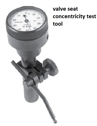
obviously dealing with a machine shop know to do quality and consistent high quality, 3 angle valve jobs is the first step in this process,
Yes ,Ive generally found you will need to disassemble and check run-out yourself and yeah,
that requires you purchase a few tools to do it accurately.

https://www.cylinderheadsupply.com/kl8545.html
valveseatest.jpg

you can generally verify valve seat seal with simply pouring alcohol into the intake or exhaust ports with what ever port your testing vertical and watching for solvent or alcohol seepage in the combustion chamber ,

alcohol will seep past a marginal valve seat seal contact far faster than water will due to its lack of surface tension, so its a better test fluid. hand lapping the valve seats tends to help.
hand lapping valve seats can be done reasonably easily and greatly increases valve seat seal.


https://www.enginebuildermag.com/2013/10/cautioning-on-valve-seat-concentricity/


http://garage.grumpysperformance.co...olishing-combustion-chambers.2630/#post-50247

http://garage.grumpysperformance.co...gree-valve-seats-tpi-motors.14662/#post-78724

http://garage.grumpysperformance.com/index.php?threads/how-to-lap-valve-seats.1159/#post-2362

http://garage.grumpysperformance.co...at-angles-and-air-flow.8460/page-2#post-32923

http://garage.grumpysperformance.com/index.php?threads/multi-angle-valve-job-related.3143/

http://garage.grumpysperformance.com/index.php?threads/what-hand-tools-to-buy.4069/#post-10827

http://garage.grumpysperformance.com/index.php?threads/what-tools-are-important.39/#post-47

http://garage.grumpysperformance.com/index.php?threads/precision-measuring-tools.1390/#post-52469

http://garage.grumpysperformance.com/index.php?threads/finding-a-machine-shop.321/#post-55314

http://garage.grumpysperformance.com/index.php?threads/bare-minimum-tools.11026/#post-51823

http://garage.grumpysperformance.com/index.php?threads/cam-degreeing.9010/#post-35474

http://garage.grumpysperformance.co...all-tools-install-info.1479/page-2#post-35245

http://garage.grumpysperformance.com/index.php?threads/porting-can-help.462/
 
Last edited by a moderator:
I was recently asked about why anyone would pay a great deal of money,
to buy high flow aftermarket cylinder heads and then,
it seems totally wrong too start grabbing a grinder or dremel tool,
to start modifying what should already be a far more precisely made cylinder head.
well there's literally thousands of potential parts combinations ,
and theres no way, that you can almost randomly mix and match,
even the best brand name components and maximize the flow rates,
without taking the time to customize the fit of those parts together.

251.gif

cosp1.jpg

cosp2.jpg

cosp3.jpg

cosp4.jpg

cosp5.jpg

cosp6.jpg

cosp7.jpg

cosp8.jpg

cosp9.jpg

cosp10.jpg

cosp11.jpg

cosp12.jpg


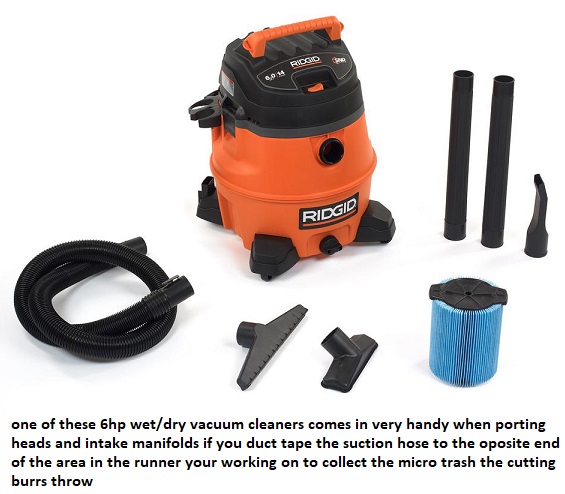
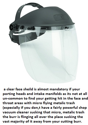
Id like to point out that if your going to port match or port heads , take the time and effort to buy and USE some safety equipment like a face shield, clear glasses and use a decent vacuum cleaner to limit flying trash, I recently had a guy I know spend several hours in the local hospital with an optical surgeon who removed an aluminum splinter from a guys eye because he was porting a set of heads without any safety equipment, that bit of lack of sense cost over $4300 , so spending less than $150 on everything you might need to do that job and dozens of similar jobs makes a great deal of economic sense and it can avoid a great deal of pain and might save your eye sight

portingstands1.jpg

http://www.summitracing.com/parts/PRO-66483/
66483.jpg

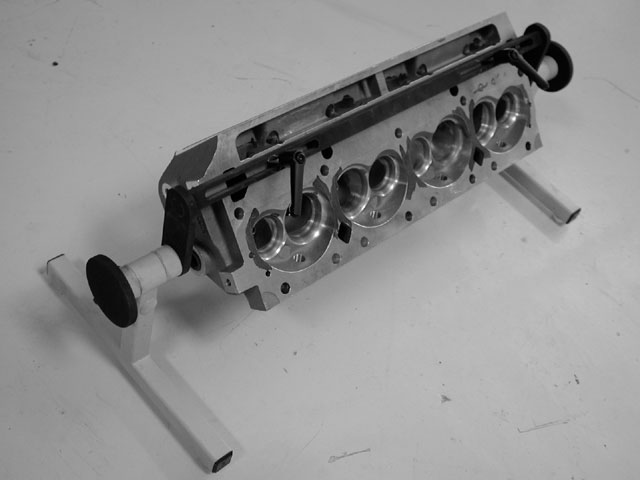
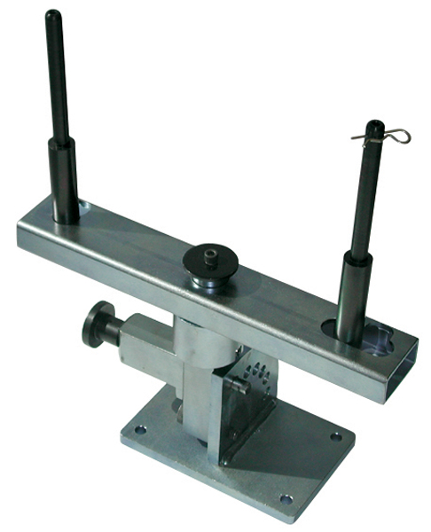
a decent cylinder head stand helps

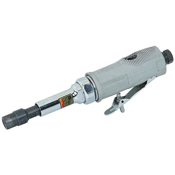
http://www.harborfreight.com/air-die-gr ... 99698.html
image_12256a.jpg

sum-900640.jpg


read these threads


https://www.homedepot.com/p/RIDGID-14-Gal-6-0-Peak-HP-Wet-Dry-Vac-WD1450/100081216?cm_mmc=Shopping|THD|G|0|G-VF-PLA-D25T-Vacs-Ridgid|&gclid=EAIaIQobChMI04eNrujh1wIVErXACh0_hgYoEAYYCSABEgLzOfD_BwE&gclsrc=aw.ds&dclid=CO7ihrro4dcCFQ_ZwAodWkUDiw
wd1450.jpg

https://www.harborfreight.com/adjustable-face-shield-46526.html
16916.jpg

https://www.harborfreight.com/safety-glasses-clear-99762.html
20519.jpg

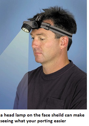
https://www.harborfreight.com/headlamp-with-swivel-lens-45807.html

22369.jpg


http://garage.grumpysperformance.com/index.php?threads/porting-can-help.462/page-3#post-67187

http://garage.grumpysperformance.co...u-buy-bare-or-assembled-heads.534/#post-57612

http://garage.grumpysperformance.co...spacers-and-related-intake-modification.1038/

http://garage.grumpysperformance.co...r-piston-dome-or-port-volume.2077/#post-44568

http://garage.grumpysperformance.co...needs-clean-up-equalization.12474/#post-62647

http://garage.grumpysperformance.co...-calculators-and-basic-math.10705/#post-46768

http://garage.grumpysperformance.co...at-angles-and-air-flow.8460/page-2#post-32923

http://garage.grumpysperformance.co...orting-tips-by-smokey-yunick.4222/#post-11120

http://garage.grumpysperformance.co...ber-from-radiusing-polishing.4390/#post-11545

http://garage.grumpysperformance.co...polishing-combustion-chambers.2630/#post-6788

http://garage.grumpysperformance.com/index.php?threads/more-port-flow-related-info.322/#post-516

http://garage.grumpysperformance.co...ing-parts-and-a-logical-plan.7722/#post-68651

http://speed.academy/cylinder-head-porting-explained-gains-worth-it/

http://www.superchevy.com/how-to/engines-drivetrain/1006chp-cylinder-head-port-design/
 
Last edited:


http://garage.grumpysperformance.co...u-buy-bare-or-assembled-heads.534/#post-57612
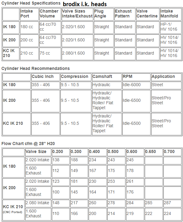
I've found BRODIX I.K. heads are very good quality, and decent value per dollar,

for a high performance street/strip style engine
https://craftperformanceengines.com...nder-Heads--brodix_cylinder_heads_sbc_ik.html
brodixik.png


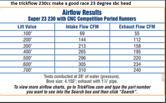
trickflow 230cc makes a good racing sbc head choice
trickflow230.png

https://www.trickflow.com/parts/tfs-3241t001-c03


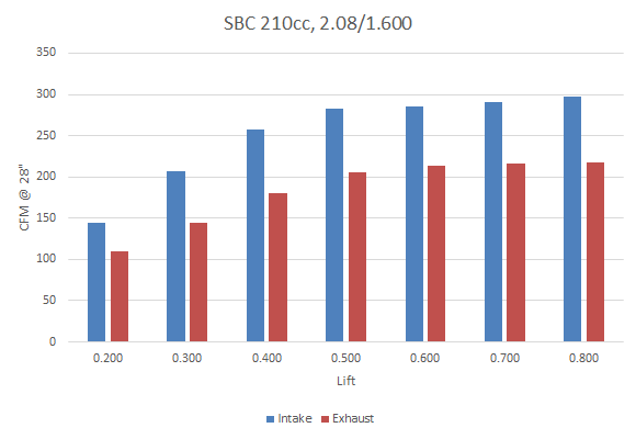
profiler 210cc is a good compromise race and street strip head
https://www.profilerperformance.com/176-sbc-23-degree-heads.html

176-210cc.png


https://www.summitracing.com/parts/afr-1055/overview/make/chevrolet
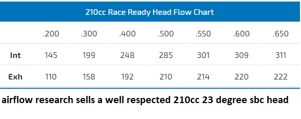
http://www.airflowresearch.com/210cc-sbc-race-cylinder-head/
afr210cc.png


related info
USE THE CALCULATORS to match port size to intended rpm levels... but keep in mind valve lift and port flow limitations[/color]
http://www.wallaceracing.com/runnertorquecalc.php
http://www.wallaceracing.com/ca-calc.php
http://www.wallaceracing.com/area-under-curve.php
http://www.wallaceracing.com/chokepoint.php
http://www.wallaceracing.com/header_length.php


https://www.profilerperformance.com/176-sbc-23-degree-heads.html

http://garage.grumpysperformance.co...olishing-combustion-chambers.2630/#post-48319

http://garage.grumpysperformance.co...r-flow-heads-the-best-choice.9415/#post-34274

http://garage.grumpysperformance.co...good-street-combo-your-after.5078/#post-14433

http://garage.grumpysperformance.com/index.php?threads/more-port-flow-related-info.322/#post-722
119651.png

119651.jpg

119651.jpg


I run into so many guys that think you can just un-package new cylinder heads and slap them on any engine they build , and expect those heads to function flawlessly.
there is almost always at least an extra 15-hp-20-hp or more potentially easily accessed through minor port clean-up.
if your willing to disassemble the heads, port match the runners and clear up the casting flaws and smooth and contour the bowl area under the valves you could rather easily double or in some cases triple those potential power gains just by improving the port contours and removing casting flaws
 
Last edited:
Back
Top