With permission by the author.
Technical Information Bulletin Rev F 4-5-05
Q-Jet Problems I have Seen
by Lars Grimsrud
Lafayette, CO
Missing Fuel Filter
Results in: Lack of a fuel filter will allow dirt and debris to get into the carb. This often unseats the needle, resulting in severe carb flooding. I have also seen this cause severe sediment build-up in the float bowl, with eventual plugging of metering orifices, resulting in poor idle and other performance problems such as jammed power piston.
Comments: A lot of Q-Jets have had their filters removed. People seem to think that the little filter in the carb must be very restrictive to fuel flow, so they toss it and install an in-line filter. Eventually, somebody removes the in-line filter, but never puts the in-carb filter back in. The in-carb filter is actually very good, and does not produce a flow restriction that will hamper a street-driven performance vehicle.
Missing Fuel Filter Spring
Results in: A missing filter spring will allow dirt to completely bypass the filter. Results in same problems as a missing fuel filter.
Comments: These springs are commonly lost during filter changes. Many people don’t see a purpose in the spring, so they leave them out. I’ve also heard people say that the spring makes the filter “block off” fuel flow, so they remove it. The spring is essential for proper filter operation.
Stripped Fuel Inlet Threads
Results in: Inability to tighten the inlet fitting with resulting fuel dripping/leaking onto the intake manifold.
Comments: Very common on the pre-’75 carbs with the smaller diameter inlet fittings. I’ve seen people try to epoxy the fittings in place. This never works. There are also over-sized self-tapping fittings available that can solve the problem temporarily, but these fittings will also strip out. There are O-Ring type adapters that can be used to seal up the inlet system, but these fittings do not allow use of the in-carb fuel filter. The only way to properly repair this problem is to have the inlet machined and tapped for a HeliCoil thread insert.
Damaged or Broken Fuel Inlet Fitting
Results in: Fuel leaking at carb inlet. Fitting cannot be tightened enough to stop leakage.
Comments: It is actually possible for the big 1” Hex fitting at the carb inlet to break internally. The cone-shaped inner seal surface breaks loose from the wall of the fitting, making the fitting appear to be a 2-piece assembly. It is also common for the cone-shaped inner seaing surface to be gouged, scratched, or damaged, making it impossible for the flared tube end to seal against it. Replace this fitting if there is any damage.
Missing Inlet Fitting Seal
Results in: Fuel leaking at carb inlet. Fitting cannot be tightened enough to stop leakage.
Comments: The early Q-Jets use a black, rubber-coated metal seal ring up against the hex nut part of the big inlet fitting as a fitting seal. Later Q-Jets use a white plastic seal ring at the end of the fitting threads as a fitting seal. These seals – not the fitting threads – seal the fitting. There is no point in using Teflon Pipe Tape on the threads to seal the fitting if these seals are missing.
Stripped Inlet Seat Threads
Results in: A loose/stripped seat in the float bowl will allow fuel to leak by the needle/seat assembly. Mild to severe flooding can result. Poor idle. Poor hot-start.
Comments: Degradation and stripping of the seat threads is common in the older Q-Jets – especially the ones that have been commercially rebuilt and sandblasted. I often see carbs with the seat epoxied into the stripped out float bowl. Epoxy will not hold the seat in the bowl for very long. The problem can only be fixed by machining and tapping the seat inlet threads for a HeliCoil insert.
Damaged/Leaking Needle/Seat
Results in: Mild to severe flooding and rich-running conditions. Poor idle. Idle mixture screws will be non-responsive. Hard to hot-start.
Comments: It doesn’t take much to cause enough damage to a needle/seat assembly to make it leak: A piece of debris passing through or damaged caused during a previous rebuild process can easily make the assembly leak. Replace the assembly anytime the carb exhibits flooding or fuel control problems.
Needle Retaining Clip Incorrectly Installed to Float Arm
Results in: Flooding, poor idle, poor hot-start, fuel puddling in bottom of intake after shut-down.
Comments: This is one of the most common assembly problems I see on Q-Jets. GM actually issued a Service Bulletin on this subject back in the late ‘60s because GM technicians were doing the same mistake. There is a small retaining wire on the needle. The float arm has two holes in it where the needle interfaces. People think the retainer goes through the float arm holes. Fact is, the retainer slips over the rear edge of the float arm, and must not be installed through the holes. Installing the retainer through the float arm holes results in the needle and/or float jamming.
Float Level Too Low
Results in: Hesitations, sluggish performance, poor idle mixture screw response, surging at cruise, “flat” feeling going to wide open throttle.
Comments: Different year Q-Jets have different float level requirements. The early carbs all have a factory spec of ¼”. The late carbs have much lower specs at about .420”. Setting up an early carb to the late spec is a common mistake, and will cause performance problems. Personally, I prefer setting up the early carbs to a float level of .300” to .375”. I run the late model carbs at .400” - .420”.
Float Level Too High
Results in: Flooding, fuel coming out of accelerator pump shaft hole, leaking air horn gasket, fuel discharging out main discharge nozzles at idle, fuel dribbling down venturi after engine shut-down, poor hot-start, hesitations off idle, poor fuel economy.
Comments: See comments above for Float Level Too Low. Often, late model carbs are set up to early model specs. This results in poor performance on the post-’75 carbs.
Incorrect Float Installed
Results in: Flooding, fuel coming out of accelerator pump shaft hole, leaking air horn gasket, fuel discharging out main discharge nozzles at idle, fuel dribbling down venturi after engine shut-down, poor hot-start, hesitations off idle, poor fuel economy.
Comments: Over the years, several different floats were used on the Q-Jets. These floats had different geometry with differing float arm lengths and different float lengths. Some floats can be interchanged, but this will result in binding, sticking and improper needle control. I also see a lot of aftermarket brass floats used in Q-Jets. The original carbs came from the factory with NitroFill floats. Brass floats do not behave the same. Be sure to install a correct NitroFill float when you work on these carbs. Echlin makes an exact reproduction and correct replacement float.
Fuel-Logged Float
Results in: Flooding, fuel coming out of accelerator pump shaft hole, leaking air horn gasket, fuel discharging out main discharge nozzles at idle, fuel dribbling down venturi after engine shut-down, poor hot-start, hesitations off idle, poor fuel economy.
Comments: Older NitroFill floats can actually become fuel soaked and start to float lower than intended. This has the same effect as raising the float level. Replace the float any time you rebuild the carb.
Float Binding Against Power Piston Tower
Results in: Flooding, fuel coming out of accelerator pump shaft hole, leaking air horn gasket, fuel discharging out main discharge nozzles at idle, fuel dribbling down venturi after engine shut-down, poor hot-start, hesitations off idle, poor fuel economy.
Comments: During rebuilding, it is easy to bump and bend the arms on the float. If the arms are squeezed together, the float arms can rub against the power piston tower, and this will restrict float movement. In severe conditions, it will prevent the needle from ever seating, resulting in severe flooding. It is also possible to bend the float arms such that the float itself rubs against the walls of the float bowl. This causes the same problem.
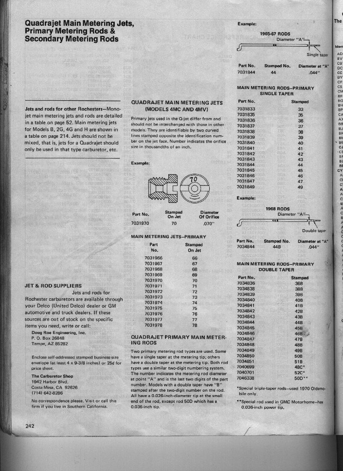
Incorrect Main Jets
Results in: Hesitations, sags, poor performance, ineffective idle mixture screws, poor idle, surging, poor mileage, poor vacuum, sooting out the tailpipes, poor starting characteristics, stumbles, poor WOT power.
Comments: “Creatively jetted” Q-Jets are more the norm than the exception. Be sure you know the stock and correct jetting configuration for your carb before you ever begin chasing problems. Always start with the correct stock jetting setup before you start tuning, and keep changes conservative: The boys and girls who designed these things in Detroit put a lot of work into the jetting configuration on these carbs, and they actually knew what they were doing…
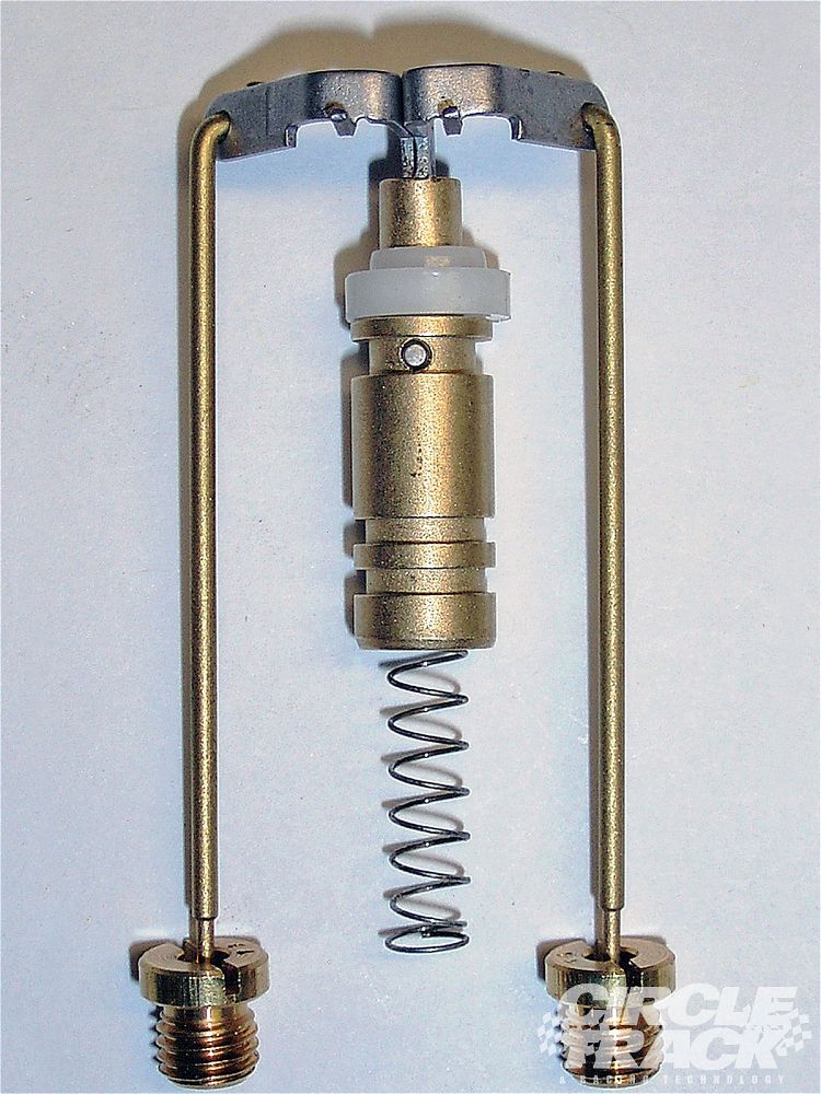
Incorrect Primary Metering Rods
Results in: Poor idle, rich idle, ineffective idle mixture screws, surging at cruise, poor mileage, poor cold-running characteristics, hesitations off idle and/or at cruise, poor manifold vacuum with resultant ancillary problems.
Comments: In addition to seeing incorrectly sized metering rods for the application, I am also seeing carbs with the WRONG rods installed. Pre-’75 (up through ’74) Q-Jets use metering rods that are approximately 2.47” long overall (total length from the metering tip to the extreme top of the rod). 1975 and newer Q-Jets use rods that are about 2.40” long. The early rods typically also have just a plain number stamped into them (like, “44”), or will often have the letter “B” after the number (like, “44B”). The later rods will often have the letter “K” or “M” after the number. If an early rod (long rod) is installed in a post-’75 carb, the actual shank (body) of the rod will be stuffed down into the jet, resulting in a severe lean condition with associated marginal drivability. Likewise, if a late rod is used in an early carb, there will be virtually no lean-out from the power piston at idle or cruise, and the carb will suffer a severe rich-running condition.
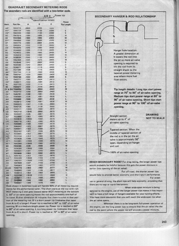
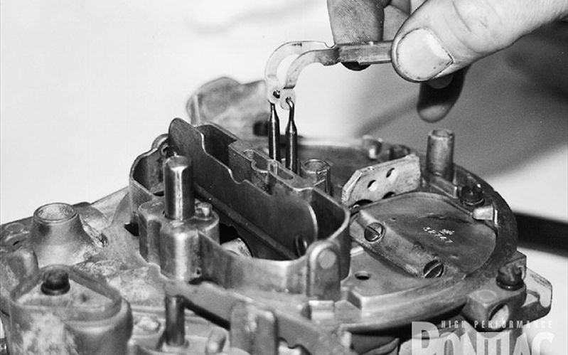
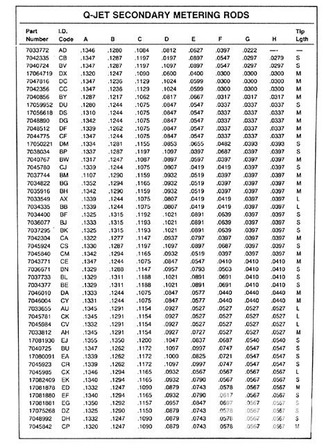
Incorrect Secondary Metering Rods
Results in: Poor WOT performance, sags or flat spots going into the secondary side, car “falling on its face” somewhere in the secondary range, smoke at WOT.
Comments: Since the secondary rods are so easy to change, they are frequently used as the “primary tuning tool” on a Q-Jet. This results in some pretty strange rods being installed. Make sure you know which rods are stock for your application, and make changes in small increments from there.
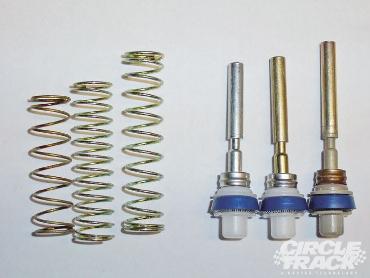
Incorrect Power Piston Spring
Results in: Poor idle, rich idle, ineffective idle mixture screws, hesitations and stumbles.
Comments: At some time, there must have been a popular article published that told people to cut their power piston springs to hop up their Q-Jet: I see more cut springs that you can imagine. A cut, or soft, spring will keep the power piston seated in the full lean position during part-throttle power, resulting in a sag and poor throttle “feel” during part-throttle acceleration. In contrast, if a stiff spring has been installed, the piston will never seat, and the carb will be running in a full-rich condition even at idle. This causes incredible tuning problems for idle and off-idle performance, and the idle mixture screws will have little effect. New power piston springs are available in packs of 10. If you suspect the spring to be non-original, stick in a new one to eliminate this as a problem.
Jammed Power Piston
Results in: Poor idle, rich idle, ineffective idle mixture screws, hesitations and stumbles.
Comments: The power piston can be jammed in either the full lean or full rich position, producing the same symptoms as an incorrect spring. You can test the power piston with the engine “off” by inserting a thin, long screwdriver down the bowl vent in the air horn. You should be able to depress the power piston and feel it pop back up. A jammed piston is usually caused by dirt entering the bowl, but can also be caused by carbon sooting up through the intake manifold from bad valves or valve timing problems.
Bent Primary Metering Rod Hanger Arms
Results in: Flooding, poor idle, hesitations, poor throttle response, poor fuel economy, ineffective idle mixture screws, sooting out the tailpipe, plug fouling.
Comments: If the primary metering rods were not engaged properly into the main jets before the air horn was installed to the fuel bowl, the rods will bend and this will also bend the piston hanger arms. If the arms are not bent back to their correct and original position, the primary metering rods will be pulled up out of the jets into the full-rich position, if they engage in the jets at all.
Bent Primary Metering Rods
Results in: Flooding, poor idle, hesitations, poor throttle response, poor fuel economy, ineffective idle mixture screws, sooting out the tailpipe, plug fouling.
Comments: If the primary metering rods were not engaged properly into the main jets before the air horn was installed to the fuel bowl, the rods will bend and fail to engage into the main jets. This causes a severe rich condition.
Cut Power Piston Lower Stop Pin
Results in: Hesitations, stumbles, poor idle, surging at cruise, ineffective idle mixture screws, hot running.
Comments: Many (not all) Q-Jets have a lower stop pin in the power piston. This pin rests against a cam in the throttle plate, and determines the lowest (leanest) position for the power piston. Cutting this pin results in the primary metering rods seating too deeply into the main jets, severely restricting fuel flow. Again, there must have been an article published at some time telling people to do this…
Incorrectly Set Power Piston Stop Height
Results in: Poor idle, rich idle, ineffective idle mixture screws, hesitations and stumbles.
Comments: Post-’75 Q-Jets have an easily adjustable power piston stop that determines the lowest (leanest) position of the piston. Raising or lowering this stop outside its limits will adversely affect all performance parameters of the power enrichment circuit. Pre-’75 Q-Jets also have an adjustable stop hidden under a steel cap in the forward side of the lower throttle plate.
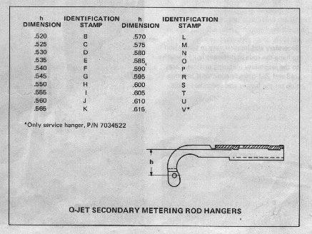
Incorrectly Adjusted Secondary Rod Hanger Height
Results in: Lean secondary performance, flat spot going into the secondaries, poor WOT power.
Comments: It is common for the secondary rod hanger to not pull the rods up out of the metering holes adequately. This produces a lean condition with associated poor power. The distance from the top of the choke rear airhorn wall to the center of the rod holes with the secondary airvalve in the wide open position should be 41/64”.
Incorrectly Adjusted Secondary Airvalve
Results in: Car falls on its face when the gas pedal is pushed to the floor, sag going into the secondaries, flat spot going into the secondaries, jerk or delay going into the secondaries.
Comments: Very common problem. The secondary airvalve is adjusted using the slotted head screw at the secondary airvalve lever, and this is released using the allen head screw up underneath the airhorn. Spring windup should be ½ to ¾ turn.
Jammed secondary airvalve
Results in: Poor WOT power and performance, car falls on its face going into the secondaries, flooding going into the secondaries.
Comments: It is a common problem on the Q-Jet for the two back screws in the airhorn to have been tightened so much that the airhorn is distorted in this area. This distortion will jam the secondary airvalves, preventing them from opening. When the secondary throttle plates are mechanically opened (pushing the gas pedal to WOT) and the airvalve is jammed closed, manifold vacuum will suck fuel right out of the secondary discharge nozzles with no airflow going through the secondary side. To fix this, the carb must be removed, and the displaced metal must be filed away. Often, the secondary airvalve plates must be loosened and re-aligned to assure a bind-free operation.
Incorrect, Missing or Damaged Secondary Airvalve Rod
Results in: Car falls on its face when the gas pedal is pushed to the floor, sag going into the secondaries, flat spot going into the secondaries, jerk or delay going into the secondaries, flooding during cold-start, erratic fast idle.
Comments: The secondary airvalve rod is one of the most misunderstood parts on a Q-Jet carb. Owners see that the rod is holding the secondary airvalve closed when the engine is running, so the rod is either removed or bent. The next guy who builds the carb installs an incorrect rod, which really screws up the secondary airvalve operation. On early Q-Jets, this rod also operates the choke vacuum break system, so removal or bending of the rod prevents the choke from cracking open during cold-start. This causes flooding and rich running in cold weather operations.
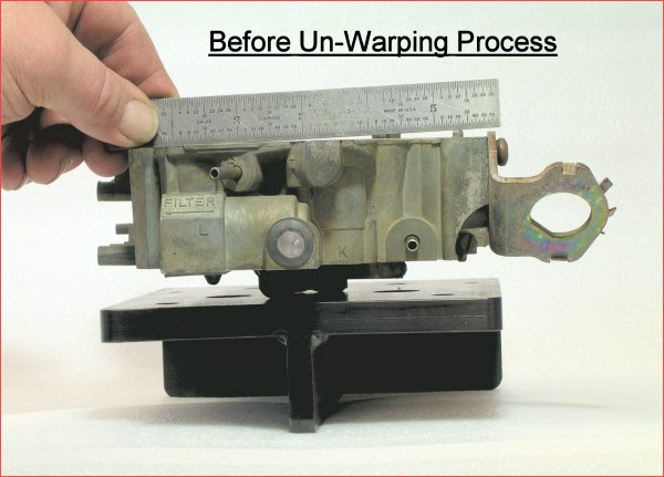
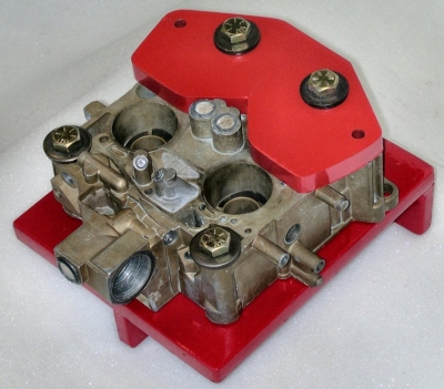
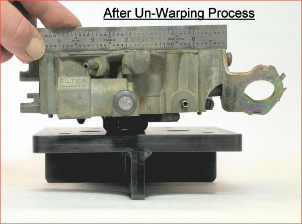
Cracked or Warped Air Horn
Results in: Fuel leaking around air horn gasket, poor idle, ineffective idle mixture screws, erratic idle, fuel discharging out main discharge nozzles at idle, hesitations & stumbles, poor throttle response.
Comments: Very common on older Q-Jets: The two forward carb hold-down bolts have been tightened so tight that the entire top of the carb is warped or cracked. Once this happens, the airhorn no longer seals properly to the float bowl of the carb. This causes leaks in the idle transfer fuel circuit between the airhorn and the bowl, effectively eliminating the entire idle circuit in the carb. It also causes the gasket to be ineffective in sealing the rest of the airhorn to the bowl, resulting in fuel leakage around the top of the carb. No fix for this – buy a new carb.
Wrong Air Horn Gasket
Results in: Poor idle, ineffective idle mixture screws, erratic idle, fuel discharging out main discharge nozzles at idle, hesitations & stumbles, poor throttle response.
Comments: Use of the incorrect airhorn gasket can result in blockage of idle bleed air passage and blockage of idle fuel passages between the float bowl and the airhorn. There are several styles of airhorn gaskets, and many of them look very similar. It’s a good idea to lay the airhorn gasket you’re going to use onto the float bowl and visually verify that all the holes line up.
Wrong Carb Major Component Parts
Results in: Bizzare performance and drivability problems.
Comments: As “numbers matching” carbs are becoming older, worn out, and more rare, people are doing some very strange things with mixing and matching components. I’ve seen many cases of “correct” Q-Jets (the carb has the right number stamed into the side of the float bowl) with air horns and throttle plates scavenged from completely different makes and model carbs. The last one I saw was a 1972 454 4-speed Vette carb (based on the number) with a 1971 Pontiac airhorn and a 1968 Impala throttle plate. Every single component in the carb, except for the float bowl itself, was incorrect and unusable. If you’re buying carbs at swap meets and on eBay, make sure you know how to visually identify the carb you’re after.
Plugged accelerator pump transfer holes in air horn
Results in: Off-idle stumble or hesitation, hard cold-start.
Comments: There is a tiny transfer hole that runs horizontally in the air horn, just inside of the actual accelerator pump discharge orifice. It is common for this to be plugged with some type of debris, especially in carbs that have been sitting around for a while. If this passage is plugged, there will not be any accelerator pump shot.
Jammed accelerator pump check ball
Results in: Off-idle stumble or hesitation, hard cold-start.
Comments: This is a common problem in carbs that have been allowed to “dry out” for a while. Sediment in the bottom of the fuel bowl will lock up the check ball as if it were set in concrete. This will prevent any accelerator pump discharge.
Accelerator Pump Rod Installed in Wrong Hole in Pump Arm
Results in: Off-idle stumble or hesitation.
Comments: There are two holes in the accelerator pump lever arm for the lever arm rod to engage into: Inner and Outer. The outer hole produces a leaner pump shot, and can cause a lean stumble on engines requiring a robust pump shot. Corvettes and performance cars always used the rich, inner pump arm hole.
Jammed accelerator pump
Results in: Off-idle stumble or hesitation, hard cold-start.
Comments: This is becoming a common problem. The alcohol additives in modern fuels are not compatible with the materials used in many accelerator pumps (even some of the pumps in brand new carb kits). This causes the pump plungers to swell up and to seize in the pump bore. The spring on the pump shaft still allows the shaft to move up and down, making it look as if the pump is functioning. But the pump itself can be seized up solid in the bore with the shaft working just fine. To fix this, you must install a pump that is specifically compatible with alcohol.
Worn accelerator pump
Results in: Off-idle stumble or hesitation, hard cold-start.
Comments: Common on older carbs and on carbs that have been allowed to dry out (vehicles stored without being started through the entire winter season). The rubber plunger material will dry out and shrivel up, making the accelerator pump completely ineffective. The pump must be replaced.
Missing idle bleed restrictors
Results in: Poor idle, ineffective idle mixture screws, off-idle hesitations, very high idle required to keep engine from dying when placed in “drive,” fuel discharging out main discharge nozzles at idle.
Comments: Different Q-Jets have different idle bleed calibrations. Part of this calibration is the installation of some brass restrictor orifices in the venturi area/booster ring area. Many commercial rebuilders will actually remove the orifices during rebuild, causing too much air to be pulled into the idle fuel circuit. The engine will then only idle if the idle speed is run up into the transition & cruise metering circuit. This is a difficult problem to diagnose and correct, since some Q-Jets did not use the restrictors, and replacement restrictors are not serviced separately.
Emulsion tubes fallen out of air horn and laying in float bowl
Results in: Poor idle, hesitations, odd & inefficient performance.
Comments: It is very common on older and high-mileage Q-Jets for the air horn emulsion tubes to fall out and end up in the bottom of the float bowl. These tubes assist in the emulsifying of the fuel mixture, and will cause a notable decrease in carb performance when they fall out. They can be re-installed into the air horn and tapped into their fully-seated position with a small plastic mallet.
Plugged idle air bleed transfer holes in float bowl
Results in: Poor idle, idle mixture screws ineffective, fuel discharging out main discharge nozzles at idle, erratic idle, high idle required to keep engine running (engine dies when idle speed is decreased).
Comments: The Q-Jet has supplementary idle air bleed holes in the throttle plate just below the primary butterfly plates. These bleed holes assure that the engine is allowed to pull enough air at idle to keep it running, while keeping the throttle plates closed far enough to keep fuel discharging through the idle metering circuit. The bleed holes act like the “drilling holes in the butterflies” trick that so many people advocate. The air for these holes is transferred from the venturi area of the carb through two small holes in the outer plenums of the float bowl. For some reason, it is very common for commercial carb builders to plug these transfer holes with aluminum plugs or rivets. This dramatically changes the idle characteristics of the carb, and frequently destroys the entire idle and cruise mixture control. If you see these plugs installed, drill them out and set up your carb the way it should be.
Leaking well plugs
Results in: Hard starting after the car has been sitting for a day or two. Flooding and black smoke when hot-starting.
Comments: This is a grossly over-rated problem. It is not by far as common as some articles and publications would have you believe. The Q-Jet uses soft metal plugs to seal off the production drill passages in the bottom of the float bowl. The passages are drilled and plugged under the main metering jets and under the secondary metering orifices, usually referred to as the primary and secondary well plugs. The primary well plugs are visible from the bottom of a fully assembled carb. The secondary well plugs are only visible and accessible once the throttle plate is removed from the float bowl. If these plugs leak, the float bowl will run empty after sitting overnight, and all the fuel will end up inside the intake manifold. You can test for this condition by simply removing the carb, filling the float bowl with fuel, and observing the plugs to see if they leak. It would be a rare condition if you actually have a leaker. But if the primary plugs leak, the only permanent solution to the problem is to drill the plugs out, tap the passages for a #10-32 screw, and install a ¼” long allen-head countersunk screw with some good epoxy into each of the two passages. I see carbs with the plugs coated with epoxy: Simply smearing some epoxy onto the well plugs will not seal them permanently. You have to drill, tap, and plug them with the epoxied screws if you want the repair to last. The secondary well plugs can be sealed by using the seal gasket supplied in all of the Echlin brand carb kits.
Porous Float Bowl Casting
Results in: Hard hot-starts due to fuel leaking into the intake manifold. Hard cold-starts due to empty float bowl. Rich idle. Ineffective idle mixture screws.
Comments: This is one of the more bizarre problems I have encountered, but I’ve seen several. Very difficult to detect if you’re just doing a quickie rebuild and slapping a carb kit in the carb, since nothing appears to be wrong. With a porous casting, fuel can not only leak through the bottom of the float bowl, but fuel can leak between the vertical fuel transfer passages that run up the forward sides of the venturis. This will cause main metering fuel to dump out the transfer fuel slots in the throttle plate. To test for a porous casting, strip the carb down to the bare float bowl. Install the needle and the seat to seal off the fuel inlet. Then, pour any type of solvent (lacquer thinner) into the float bowl and fill it to within 3/8” of the top of the bowl. Let it sit for a few minutes. Then, without allowing the solvent to spill, raise the float bowl so you can inspect the bottom of the bowl for any seepage or leaks. There should be no wet spot or drips at all coming from anyplace on the float bowl. Accessible porous spots can be cleaned up and sealed with JB Weld.
Undrilled Passages
Results in: Unexplainable fuel metering problems, either running too rich or too lean in one or more modes of operation, and normal jetting corrections will not fix it.
Comments: Another one of those odd, rare problems, but they do occur. I have seen several carbs that have had fuel and vacuum transfer holes missing from the factory – the holes will be partially drilled, with evidence that the tooling drill bit broke during the operation. These carbs have run poorly since the car was built, and often these carbs will have some very strange jetting combinations and setups due to somebody trying to tune the carb without realizing that a hole was missing.
The most common undrilled hole is the power piston vacuum passage in the throttle plate on 1975 – 1980 Q-Jets. This hole was drilled in 2 operations: halfway through the throttle plate from the top, and then at a 45-degree angle up from the bottom to intersect the top hole. When this hole is missing, the power piston stays in the full rich condition at all times, causing horrible idle problems.
The second most common undrilled passage is the ported vacuum pickup hole in the 1968-1971 carbs. Many of these carbs have a throttle plate that has no hole for the ported vacuum source, resulting in the ported vacuum nipple on the forward passenger side of the carb being a plugged, dead end port. Since most stock vacuum advance systems run off this port, the undrilled passage results in no distributor vacuum advance with associated poor mileage and poor throttle response at cruise. To test for this condition, simply attach a vacuum hose to the nipple and blow in it: you should be able to blow through the hose. If not, you need to drill the hole in the throttle plate.
When building a Q-Jet, I like to use the little red plastic nozzle tube that comes with every can of WD40 and blow a wad of WD through each passage. I also trace out the passages as they connect from the float bowl to the throttle plate to make sure they form a complete circuit. Doing this is actually fun for the novice, since you gain a very good understanding of the carb operation when you spend 10 minutes tracing out the passages.
Eroded or Mismatched Secondary Fuel Passages
Results in: Massive bog when going into the secondaries. Vehicle falls on its face, and may backfire up through the carb.
Many of the commercially rebuilt carbs get sandblasted by the rebuilders, and assembled using various parts and components from various different carbs. This can result in 2 conditions preventing secondary fuel flow:
First, the top of the float bowl casting in the secondary fuel passage area (the two big holes in the casting coming up just at the back wall of the float bowl, forward of the secondary venturies) get eroded and worn down by the sandblast process. When this happens, the top surface of these transfer hole passages will not seal tightly against the mating passages in the airhorn (the “top” of the car). When the secondaries open up and attempt to siphon secondary fuel out of the secondary discharge tubes (the two tubes sticking out at an angle out of the airhorn under the airvalves), nothing but air is siphoned through this leak.
Second similar problem occurs when an airhorn from one carb is used on the float bowl from another carb: If the warpage in the airhorn does not match the warpage of the float bowl, there can be an airgap between the two components in this critical transfer passage area.
HeliCoiled Main Metering Jet Holes
Results in: Rich running carb throughout the operating range.
Many commercial rebuilders will attempt to save a stripped out float bowl casting by installing a HeliCoil in the main jet holes. When drilling and tapping for the HeliCoil, the counterbored sealing surface for the jet is removed, and the main jets can no longer seal around their perimeter: fuel will leak down around the outside of the jets as well as being metered through the center of the jets. A carb float bowl with a stripped or HeliCoiled main jet hole cannot be saved - it goes in the trash can.
Wrong throttle plate gasket
Results in: Poor idle, erratic idle, ineffective idle mixture screws, symptoms of a vacuum leak.
Comments: There are several different designs for the throttle plate gasket, and they do not interchange. Two common problems occur: The first problem was addressed in a GM Service Bulletin around 1971. There is a difference in the open area in the gaskets just forward of the centerline of the primary throttle holes. Some later carbs use a gasket with a larger open hole in this area. If this gasket is used on an earlier carb, you will end up with a massive, undetectable vacuum leak. The other problems with these gaskets occur due to the idle fuel and vacuum bleed holes not lining up from one design to the next. Use of the incorrect gasket can result in blocked idle fuel and blocked vacuum signals. Always lay the gasket onto the float bowl and onto the throttle plate to check the hole alignments.
Another odd twist to these gasket designs occurred in the late ‘80s. We are seeing more and more late ‘80s truck Q-Jets (non-ECM carbs) being used on musclecars, so the problems are becoming more frequent: In the late ‘80s, there is a fuel discharge hole drilled from the secondary fuel well to a small hole located between the secondary throttle holes in the base of the float bowl. Carbs with the fuel hole require use of a gasket that has NO HOLE at this location. If a standard late ‘70s or early ‘80s gasket is used with this carb, manifold vacuum will siphon fuel right out of the secondary side of the carb, discharging the fuel right out of the power brake vacuum hole location in the bottom of the carb throttle plate. You will have a massive rich-running condition, even with the idle screws completely closed (blocking all primary fuel flow) and with no evidence of fuel being discharged on the primary side.
Loose throttle plate
Results in: Erratic idle, poor idle mixture screw response, off-idle hesitations, symptoms of a vacuum leak.
Comments: Since the throttle plate attach screws are located in the bottom of the carb, you cannot tell that the screws are loose until the carb is removed from the engine. It is quite common for the screws to be loose, producing not only a vacuum leak around the base of the fuel bowl, but violating the seal for the idle fuel transfer passages. This makes adjustment of the idle mixture and idle speed almost impossible.
Wrong idle mixture screws
Results in: Poor idle screw mixture response, poor idle, erratic idle.
Comments: There have been several styles of idle mixture screws used in the Q-Jets over the years. The screws differ in the taper of their tips: Some screws have a steep taper, while others are very long and slender. Commercial rebuilders typically remove the nice factory screws and install aftermarket one-size-fits-all steep-taper screws. These steep-taper screws often do not work at all in many Q-Jets. Most of these steep-taper screws are brass. All factory Q-Jet idle mixture screws are steel. If you have a set of brass idle mixture screws in your carb, trash them and find a correct set of factory screws.
Seized/rusted idle mixture screws
Results in: Adjustment of idle mixture not possible.
Comments: A lot of the cars used in the Midwestern and Coastal States have severe corrosion problems, as we know. The steel mixture screws in the aluminum throttle plate promote dissimilar metals corrosion, and can often seize solid into the throttle plate. Attempts to force them out will usually result in the screws snapping off in the throttle plate, rendering the carb useless. To remove rusted and seized mixture screws, the throttle plate must be removed from the carb, and the screws must be carefully heated while “rocking” them back and forth to loosen them up.
Seized/rusted fast idle screw & cam
Results in: Adjustment of fast idle not possible.
Comments: The same cars with the rusted and seized idle mixture screws will quite often also have rusted & seized fast idle screws and idle cams. Once again, any attempt to force the fast idle screw will usually result in the screw snapping off in the fast idle lever. To remove rusted and seized fast idle screws, the throttle plate must be removed from the carb, and the screw must be carefully heated while “rocking” it back and forth to loosen it up. To loosen the cam, the throttle shaft cam screw must be carefully removed, and the spring & linkage pieces must be carefully pried loose, cleaned up, and re-assembled.
Primary throttles adjusted to not open fully
Results in: Poor throttle response, poor WOT performance.
Comments: It is amazing how common it is for the throttle linkage on the carb to be grossly misadjusted. When rebuilding a carb, always operate the throttle linkage and make sure the primary throttles open fully. They should open the the exact vertical position. Anything less will prevent full airflow through the carb. The position of the blades is adjusted by bending the throttle stop linkage.
Primary throttles adjusted to open over-center
Results in: Poor WOT performance.
Comments: Even more common that throttles that do not open fully are throttles that have been adjusted to open over-center. I guess people figure that te car will run faster if you can open the throttle even more. Fact is, once the throttle blades go over-center, they are restriction airflow just as bad as a throttle that does not open fully. Check for an over-center condition anytime you rebuild you carb, and bend the linkage so that the throttles stop at the vertical positioon.
Secondary throttles adjusted to not open fully
Results in: Poor WOT performance.
Comments: The secondary throttle shaft is actuated by a link off the primary shaft that hits a lever on the secondary throttle shaft. It is common for this to be misadjusted so that the secondary throttle blades do not fully open. Some factory cars & carbs were intentionally set up to limit secondary throttle opening (like 1st-generation 400-powered Firebirds) in order to limit horsepower for one reason or another. Check for this whenever the carb is disassembled and adjust it by bending the contact tang on the primary throttle shaft.
Secondary throttles adjusted to open over-center
Results in: Bog or hesitation going into the secondaries, poor WOT performance.
More common that secondaries that do not open fully are secondaries that open too far. Q-Jet secondary throttle plates should NOT open to the full vertical position or beyond. The secondary throttle plates should open to a position where the angle of the throttle plates points and aligns towards the lower edge of the secondary airflow baffle located in the secondary venturi bore. When the secondary throttle plates are opened beyond this point, turbulence in the secondary side actually decreases airflow. Also, if the secondary throttle plates are adjusted to open over-center, they will, as a result, also open too soon. This will cause a stumble or hesitation going into the secondaries. Adjust and align the opening by bending the primary throttle contact tang.
Secondary throttles not closing – not aligned in bores
Results in: Fuel discharging out the secondary discharge nozzles at idle & cruise, poor idle, flooding, black smoke, off-idle stumble.
Comments: If the secondary throttle plates do not fully close, or if they are misaligned in their bores, engine vacuum will be applied to the secondary venturi area. With engine vacuum in the veturi area, and the upper airvalves closed, fuel will be siphoned out of the secondary discharge nozzles. This will cause a very rich idle and cruise condition. The problem can be caused by the secondary throttle linkage being bent/misadjusted, or by the secondary butterflies being misaligned in the throttle plate bores.
Secondary throttle linkage springs missing or incorrectly installed
Results in: Secondary throttles not closing (see above), secondary throttles inoperative.
Comments: There is no reason to disassemble and remove the secondary throttle shafts, throttle plates, and the associated springs during a rebuild, but some people do it anyway. During re-assembly, these parts get left out or incorrectly assembled, resulting in the secondary throttle plates not closing fully or no longer actuating at all. These problems can be hard to identify unless you are very familiar with the Q-Jet or unless you have another carb to compare against.
Missing secondary airflow baffle
Results in: Poor secondary WOT performance, sags or hesitations at WOT.
Comments: The baffle installed inside the secondary venturi area actually creates the venturi effect required to discharge the fuel properly out of the secondary discharge nozzles. Deleting the baffle causes turbulence in the secondary venturies that will completely mess up your secondary metering. Make sure the baffle is correctly in position. It is frequently missing.
Choke plate misaligned
Results in: Poor cold-running characteristics, sticking choke, engine stalling when cold, engine not coming down off fast idle unless gas pedal is hit.
Comments: If the choke plate is misaligned in the airhorn, the choke can stick and bind in a part-closed position. It cam also fail to close completely during initial cold-start. Check to make sure the plate fits squarely and tightly in the air horn. If not, crack the two screws loose and wiggle the plate around until it fits right.
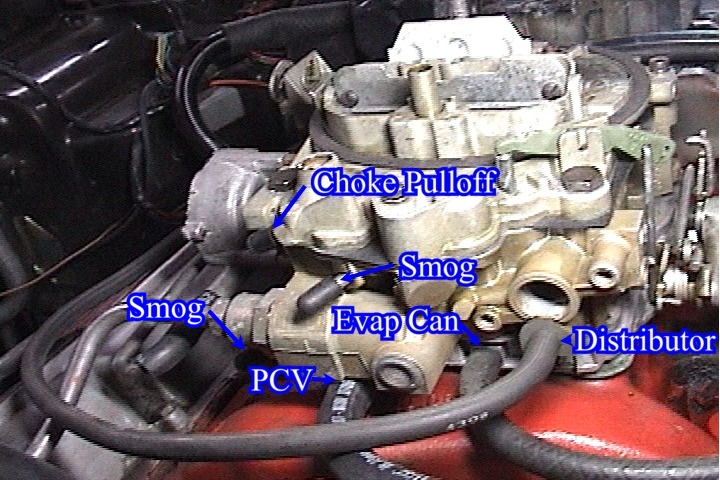
Choke pulloff seized or ruptured
Results in: Poor cold-run characteristics, flooding when cold, stalling when cold, poor fast idle control, sag or hesitation going into the secondaries.
Comments: This is one of the most common maladies on older Q-Jets. When the pulloff fails, not only do you loose proper control over the choke, but you also loose opening rate control over the secondary airvalve. Always check the pulloff by attaching a long piece of vacuum hose to it and sucking on it. The pulloff should smoothly retract, and it should smoothly extend when the suction is released.
Choke pulloff incorrectly adjusted
Results in: Poor cold-run characteristics, stalling when cold, flooding when cold, engine won’t stay running after cold start-up.
Comments: The primary purpose of the choke pulloff is to crack the choke open just a tad upon initial cold-start. If the choke is not cracked open, the engine will flood. If the choke is cracked open to far, the engine will lean out and stall. When correctly adjusted, the choke pulloff will open the choke ¼” as measured from the forward lower edge of the choke plate to the airhorn wall.
Fast idle screw incorrectly adjusted
Results in: Initial cold-startfast idle too high or too low.
Comments: The fast idle screw is hidden so well that many people don’t know it even exists. The screw is located under the choke linkage on the passenger side of the car. The screw head faces forward. Fast idle speed should be adjusted to about 1200 rpm on a cold engine.
Choke linkage/intermediate shaft system incorrectly assembled or missing pieces
Results in: Inoperable choke, engine not coming down off fast idle, sticky choke.
Comments: The choke and fast idle linkage on a Q-Jet can be a mystery of odd parts once the carb is fully disassembled. It is easy to get some of the pieces incorrectly assembled or installed in a bind. When this happens, the choke system will not operate properly. Best to take a look at another carb and do a little comparison if you’re not intimately familiar with the linkage system.
Broken choke housing
Results in: Poor choke performance, inoperable choke, vacuum leak.
Comments: The 1975 and newer Q-Jets use a cast aluminum choke housing for either a hot air choke or for an electric choke. Many carb kits contain new choke hosing screws, and these screws are often too big for the intended application. Installation of the aftermarket screws will crack the choke housing, and can make it impossible to properly adjust the choke cover. The hot air chokes have a vacuum source from the inside of the choke cover to draw hot air through the choke system. If the housing is cracked from the oversized screws, and the choke cover is not tightly installed, the vacuum source will not pull the hot air through the system properly, and the choke will remain “on” too long. Broken housings can be welded.
Missing choke intermediate shaft seals
Results in: Sticky choke operation due to dirt contamination.
Comments: The 1975 and newer Q-Jets use two shaft seals on the choke intermediate shaft: One seal is installed inside the choke housing, and the other seal is installed in the carb float bowl where the shaft goes through the side of the bowl. Failure to install the seals can result in a sticky choke system.
Missing secondary lockout lever
Results in: Bogging, sag or stumble when going to WOT with a cold engine. Engine damage from going to WOT on a cold engine.
Comments: The secondary lockout lever, located on the passenger side of the carb just forward of the secondary throttle shaft, is intended to prevent the secondaries from opening when the engine is cold. Placing the engine under maximum load before reaching normal operating temperature can result in engine damage. The lever is retracted by the choke linkage as the choke opens up. Many people are afraid that the lockout lever is preventing the secondaries from opening, so they remove the lever. This is fine on a racecar, but not advisable on a street car. Make sure your choke is operating, and make sure the lever is adjusted correctly to perform its intended function. When properly adjusted it will retract when the engine has warmed up, and the secondaries will function as intended.
Incorrectly adjusted secondary lockout lever
Results in: Inoperable secondaries.
Comments: It is possible to have the lockout lever and the secondary throttle shaft pin adjusted so that the secondary throttles remain locked out even after engine warm-up. Check the lockout lever once the choke is wide open and assure that the lever does not interfere with throttle opening.
Missing idle vent parts
Results in: Dirt & debris entering the float bowl.
Comments: The early Q-Jets use an idle vent valve on the forward, upper part of the carb. The idle vent valve consists of two stainless steel “reed” pieces, a rubber seal, an actuation rod to the accelerator pump lever arm, and a sheet metal “doghouse” to cover all the parts. Over the years, many carbs have come up missing some or all of these parts. This not only results in a carb that looks incorrect and incomplete, but the resulting hole in the top of the carb is a perfect source for contamination of the carb float bowl.
Incorrectly adjusted idle vent
Results in: Engine stalling/flooding when hot idling.
Comments: The idle vent valve is to be adjusted so that the vent is cracked open when the throttle is at idle, and it should close when the throttle is moved off-idle. If the vent does not open at all at idle, the engine may display poor hot idle characteristics and stalling when hot. If the valve is adjusted so it never closes at cruise, dirt and debris can enter the float bowl.
Wrong accelerator pump linkage installed
Results in: Off-idle hesitations, stumbles, flat spot when accelerating.
Comments: Different model Q-Jets use different length accelerator pump actuation rods. Many of these carbs have been pieced together by rebuilders using various different parts. If the incorrect pump rod has been installed, the accel pump may be inoperable for the initial part of its travel, or the pump may bottom out in the pump bore too early in the throttle travel. Poor throttle response and/or hesitations will result.
Wrong accelerator pump installed
Results in: Off-idle hesitations, stumbles, flat spot when accelerating.
Comments: Just like the pump actuation rod, different Q-Jet models use different length accelerator pumps. Use of an incorrect length pump will change the geometry of the accelerator pump linkage, and can result in an inadequate or delayed pump shot. After rebuilding a carb, always visually inspect the function of the accelerator pump to assure that the pump is discharging fuel into the primary venturis upon the slightest movement of the throttle (do this with the carb primed and the engine off).