Valve Guide Reconditioning
http://www.enginebuildermag.com/Article ... oning.aspx
By Larry Carley
Larry Carley
The condition of the valve guides in an engine is extremely important because they support the valve stems and cool the valves. But worn guides increase oil consumption, and too much clearance between the guides and stems can make the valves run hot, increasing the risk of burning an exhaust valve. A valve loses about 15 to 30 percent of its heat through the stem. On the exhaust side where there is no cooling effect from the incoming air/fuel mixture, the guides are critical, because cooling through the stem is especially important for valve longevity.
Worn intake guides or ones with too much clearance can also allow "unmetered" air to be drawn into the intake ports. The effect is similar to that of worn throttle shafts or a vacuum leak in the intake manifold: the extra air reduces intake vacuum and upsets the air/fuel calibration of the engine at idle, which may contribute to a lean misfire condition or a rough idle.
There’s also the problem of loose guides. Some cylinder heads such as those on Chrysler/Mitsubishi 3.0L V6 engines are notorious for loose guides. In such cases, it may be necessary to install oversized replacement guides to fix the head.
Simply put, valve guides can have a big impact upon an engine’s performance.
How you choose to recondition the guides will vary depending on what kind of engine rebuilding operation you have. Large production engine rebuilders typically have a set procedure for reconditioning all the guides based on which method costs the least and yields the best results for them. They may ream out the old guides and install new valves with oversized stems or rechromed stems, or they may ream out the old guides and install bronze guide liners to restore the original clearances. Performance engine builders often prefer bronze guide liners to improve lubricity and resistance to seizure. Custom engine builders may use either method depending on customer preferences and how much a customer wants to spend.
On aluminum heads with replaceable guides as well as cast iron heads with non-integral guides, worn guides can be reconditioned by driving out the old guides and replacing them with new ones, reaming the original guides to oversize to accept valves with oversized or rechromed stems, or reaming out the worn guides and installing guide liners. Most shops that work on aluminum heads usually replace the guides if they are worn. Hard powder metal guides can be difficult to ream so that’s why they often replace rather than recondition the guides. But new solid carbide reamers are available that have a six-flute design and can cut powder metal guides as easily as cast iron guides.
On cast iron heads with integral guides, the most popular methods of reconditioning guides is to ream out the guides to accept valves with oversized or rechromed stems, or to ream out the guides and install guide liners. In cases where the original integral guide is too badly worn or damaged to accept an oversize valve or a guide liner, some heads may be salvaged by installing a whole new guide.
When used valves are salvaged and the stems are reground, grinding removes the chrome flashing. Chrome prevents the stem from galling when cast iron guides are used, and it helps prevent positive valve seal wear on intake valves. If the chrome is ground off and the valve stem is not replated, it must be used with either a bronze liner or guide.
Knurling is another technique that can be used to restore guide clearances, but only if guide wear is limited (.006Ë or less). Most engine builders today see knurling as a “temporary†fix that only provides limited benefits and won’t last over time. When the knurling tool is run through a guide, it leaves behind a spiral groove that acts like a furrow to raise the metal on either side. This reduces the inside diameter of the guide so a reamer can then be used to resize the guide back to (or close to) its original dimensions. The grooves also help retain oil for improved lubricity, which means you can tighten up clearances a bit compared to stock. But the bearing surface area created by knurling is not as great as a smooth surface, so over time it will wear more quickly.
So how do you decide which method is the best one for you? There’s no easy answer to that question because the answer depends on the type of head that’s being reconditioned, your labor costs, how competitive you have to be with your pricing, how much your parts cost, what percentage of valves you can salvage, whether you buy rechromed valves or rechrome used valves yourself, and most importantly what your customers want.
The bottom line is that you want to use a guide reconditioning method that is reliable, affordable, profitable and doesn’t cause problems down the road.
New Valve Guides
If you opt to replace the original guides, the old guides are easiest to remove when the head is warm. This can be done just after the heads have come out of a cleaning oven or spray washer. The removal procedure will vary depending on the head, but most can be driven out pneumatically.
Chilling the replacement guides can reduce the amount of interference during installation. Using a lubricant can also reduce the risk of galling. With tapered guides, care must be taken to install them from the right side. Most wet guides are tapered, and also require sealer to prevent leaks.
If the old guides are loose, the holes will have to be machined to oversize to accept new guides with oversized outside diameters. The amount of interference fit should be the same as before, or slightly higher if the head has a reputation for loose guides.
Replacing the guides may change the concentricity of the valve slightly with respect to the seat, but this should be restored when the seats are recut using a centering pilot in the guide.
As for the type of guide to install, many shops use the same type as the original and replace same with same (bronze with bronze, cast iron with cast iron, or powder metal with powder metal). Powder metal guides may be more expensive, so for some applications it may be more economical to substitute cast iron or bronze guides for the OEM powder metal guides. But these other materials may not provide the same longevity as powder metal.
Guide Liners
Liners have long been used to repair worn integral guides in cast iron heads, but can also be used to restore worn cast iron guides in aluminum heads. The main advantage with this approach is that valves and guides don’t have to be replaced. This assumes the original guides in an aluminum or cast iron head with non-integral guides are still tight and that the original valve stems are not worn excessively (worn valves can be reground to fit liners with undersize IDs). The cost savings can be significant depending on the application, and it eliminates the labor and risks of driving out the old guides and installing new ones. Powder metal guides tend to be brittle and can be difficult to replace.
Bronze liners provide good lubricity and reduce the risk of galling and seizure. On the other hand, installing liners requires a couple of extra steps, which must be done properly to assure proper clearances and fit.
If you opt for liners, there are several from which to choose: thin wall phosphor bronze in various configurations (split and solid designs), and cast iron.
The key to using a split type of bronze liner is proper installation. The original guides should not be worn more than .030Ë or cracked, otherwise replacement is recommended. The first step is to bore out the guides to accept the liners. Use a carbide reamer in an air drill with a no load speed of 2,100 to 3,000 rpm. Special fixtures are available with centering pilots that center the reamer off the valve seat rather than the guide hole to maintain seat concentricity. Guides should be bored dry with no lubricant, using steady consistent pressure.
Once the guides have been bored out, they should be blown out and checked with a go-no go gauge to make sure they’re the proper size. Next, the liners are pressed in – usually from the top of the head using an air hammer and installation tool. But on some aluminum heads with powder metal guides, better results can be achieved by installing the liners from the combustion chamber side. Liners go in with the tapered side facing the guide hole. The liners are then driven in flush with the top of the guide.
Sizing the inside diameter of the liner is the next step. Any of three different techniques may be used: roller burnishing (use with lubrication), broaching (driving a calibrated ball through the liner with an air hammer), or using a ball broach tool in an air hammer. This is the most important step because it provides the proper clearances between valve stem and liner for good lubrication and oil control, and it locks the liner in place so it will transfer heat efficiently to the head.
Once the liners have been sized, the head can be turned over so the liners can be trimmed to the proper length unless precut liners are used. Liners are usually cut flush with the guide boss in the port.
The final step is to flex hone the liner. Honing removes any burrs left from trimming the liner to length, and leaves a nice crosshatch finish that improves oil retention. One pass in and out is all that’s recommended to hone the liner. A flexible nylon brush should then be passed through the liner to clean the hole.
With some one-piece bronze liners, broaching after installation is not necessary. The liners have an interference press fit of about .001Ë to .0015Ë, which requires boring the guide to exact dimensions. Broaching is required for cast iron liners, though, to seat the liner in the guide.
Oversize Valve Stems
Valves with oversized stems are typically available in a range of sizes including .003Ë, .005Ë, .008Ë and .015Ë, with the .015Ë being the most popular because it can accommodate greater wear in the guides.
Installing new or rechromed valves with oversized stems is essentially a two step operation as far as guide reconditioning is concerned. Step one is to ream the guides to oversize. Step two is to finish the holes with some type of honing tool. A reamer fractures metal and leaves microscopic pullouts, tears and a relatively rough guide surface. Even new guides can be rough inside. Honing removes this debris from the surface, improves oil retention and allows somewhat closer stem to guide clearances for better oil control and heat transfer.
One supplier of rechromed valves said, "One of the biggest changes in this industry today is that rebuilders are realizing their niche isn’t salvaging small parts like valves, it’s building engines and salvaging the large high dollar parts. Rechromed valves can be very price competitive with new valves, and save rebuilders the cost and hassle of reconditioning their own valves."
Fred Calouette of Cal Valves, Escanaba, MI says his oversized valves not only eliminate the need for guide liners or replacement guides, but they also solve a lot of problems for rebuilders who use salvaged valves.
"In addition to cleaning, inspecting, hard chroming and precision grinding valves to standard or oversize dimensions, we can also test valves for cracks and hardness. We can do custom valves on a limited or production basis, and can shorten valves if a rebuilder needs a shorter valve to compensate for valve seat refinishing or push rod adjustment."
"If a rebuilder is involved with an OEM engine program and has to use OEM valves, we can give him back reconditioned OEM valves so he doesn’t have to buy new valves. We have over 300 part numbers for both heavy-duty diesel trucks and passenger cars."
Calouette said that in spite of a lackluster year for aftermarket engine builders, his business is up 10 percent this year and will probably finish 12 to 15 percent higher by year’s end.
Clearances
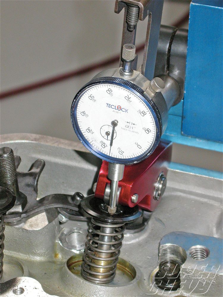
Guide clearance can be checked after cleaning the valve stem and guide with solvent and a brush to remove all gum and varnish. Insert the valve into its guide, then hold it at its normal opening height while checking side play with a dial indicator. If play exceeds the specified limits, measure the valve stem with a micrometer to see if it is worn excessively (more than .001Ë of wear calls for replacement).
A fast way to check guide wear is with a gauge set designed for this purpose. A gauge set will give you precise measurements and can be used to measure any portion of the guide.
To measure guide wear (as well as taper) using a telescoping or split ball gauge, measure the guide ID at both ends and in the middle. Subtract the middle reading from the ends to determine taper wear. Compare the smallest ID measurement (usually in the middle of the guide) to the factory specs to determine total wear.
Do not use a valve seat grinding pilot to check guides. A valve guide pilot will fit snugly in the unworn center section of the guide but not give a true indication of the amount of bellmouth wear at the ends of the guide.
Valve stems should also be measured to check for sizing as well as wear. Nominal sizes vary quite a bit depending on the application, and there’s no way of knowing if a valve has been replaced previously with one of a different size unless the stem is measured. Many late model engines have tapered valve stems. Taper stem valves are ground with the stem diameter smaller at the head end of the valve. This is done to create a larger clearance at the head where the temperatures are highest. This reduces the change of galling with unleaded fuel and narrow three-angle valve seats. When measuring a tapered stem, check the outside diameter about an inch in for each end.
Different engines have different clearance requirements, so always refer to the factory specifications. Stem-to-guide clearances normally range from .001Ë to .003Ë, and .002Ë to .004Ë for exhaust guides. The exhaust guides usually require .0005Ë to .001Ë more clearance than the intakes for thermal expansion.
Diesel engines as a rule have looser specs on both intake and exhaust guides than gasoline engines, and heads with sodium-filled exhaust valves usually require an extra .001Ë of clearance to handle the additional heat conducted up through the valve stems.
The type of guide also influences the amount of clearance needed. Bronze guides, as a rule, can handle about half the normal minimum factory clearance specified for cast iron guides or integral guides because of the anti-seize characteristics of the material and its superior oil retention qualities. A knurled guide, one with oil retention grooves or a bronze threaded liner all provide better lubrication than a smooth guide. Consequently, clearances for these types of guides can also be tighter. Half the factory minimum specified clearance is sometimes acceptable.
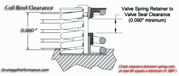
The type of valve seal used also has a bearing on clearances. Positive valve seals, which are used on most engines today, reduce the amount of oil that reaches the valve stem compared to deflector or umbrella type valve seals. A guide with a deflector valve seal in an older engine application may need somewhat tighter clearances than one with a positive valve seal to control oil consumption.
Unusual Guide Wear
All guides will show some wear at high mileage, but excessive wear or unusual wear may indicate other problems that need to be addressed. Severe guide wear may be due to inadequate lubrication, improper valve geometry or wrong valve stem-to guide clearance (too much or too little).
Inadequate lubrication may be caused by oil starvation in the upper valve train due to low oil pressure, obstructed oil passages, push rods, etc. Lack of oil can cause stem scuffing, rapid stem and guide wear, possible valve sticking and ultimately valve failure due to poor seating and overheating.
Geometry problems include the wrong installed valve height, and off-square springs, rocker arm tappet screws or rocker arms that push the valve sideways every time it opens. This causes uneven guide wear, leaving an egg-shaped hole. The wear leads to increased stem-to-guide clearance, poor valve seating and premature valve failure.
Installing new guide liners is a five-step process.
Bore: Using a carbide boring tool with a high RPM air drill, bore out the original guide.
Install: Blow away chips and lube the guide hole with appropriate lubricant. Install valve guide liner into holder assembly of installation tool. Drive guide liner into place using short-stroke heavy-duty air hammer.
Size: Finish the procedure using one of the following methods:
Ball Broach: Insert the ball broach into guide and drive by air with a broach holder and air hammer.
Roller Burnish: Use with a heavy-duty air drill. Insert burnisher into guide and allow self-feeding action to finish the process.
Carbide Ball: Rest ball on top of guide liner and drive using a pneumatic ball driver and air hammer.
Trim: Insert appropriate size pilot into carbide guide cutter. Use a 950 rpm air drill to remove any excess liner material from each side of the valve guide.
Flex Hone: Run the appropriate sized Flex-Hone through the new guide liner using a 2,100 rpm drill. One pass up and one pass down will provide the desired finish.
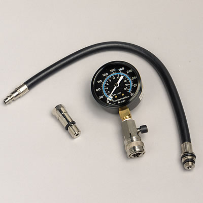
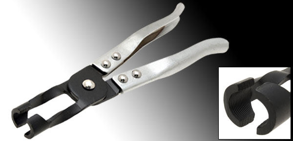
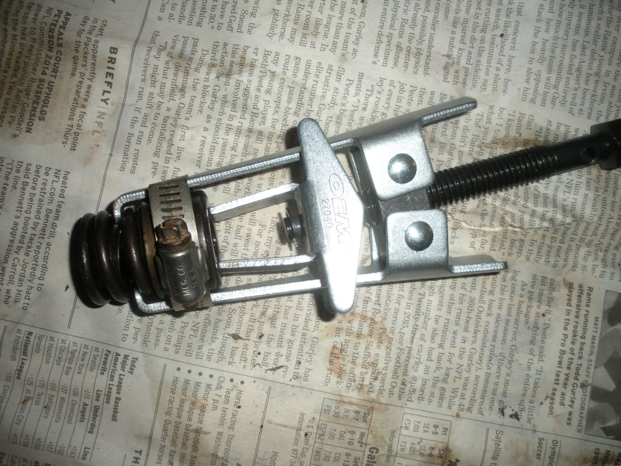
The valve spring compressor should be available for free (deposit required) at your favorite auto parts store. The air pressure trick isn't the only alternative, and sounds a bit awkward, especially at cyl #8. I'd like to hear from someone who's actually done it, rather than theory.
Another way that sounds reliable (but I haven't tried it myself . . . see para. 1!) is to remove all spark plugs and rocker arms, then rotate the engine so the piston of the cyl. being worked on is down. Push about a foot of soft rope, about 3/16 dia., into the cylinder, then rotate the engine until the rope is pushing against the valves. After the seals and valve springs are replaced, back the engine off the rope and pull it out.
The spring compressor I borrowed worked better with a hose clamp around it to keep the spring from popping out.
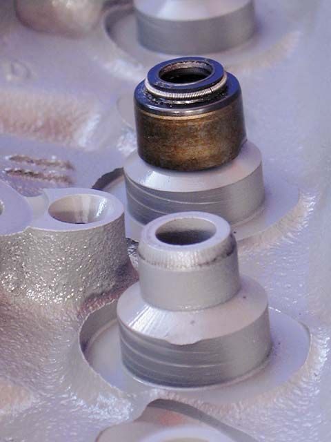
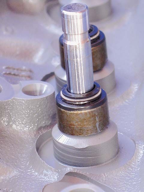
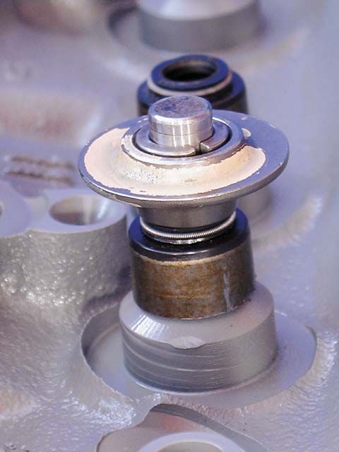
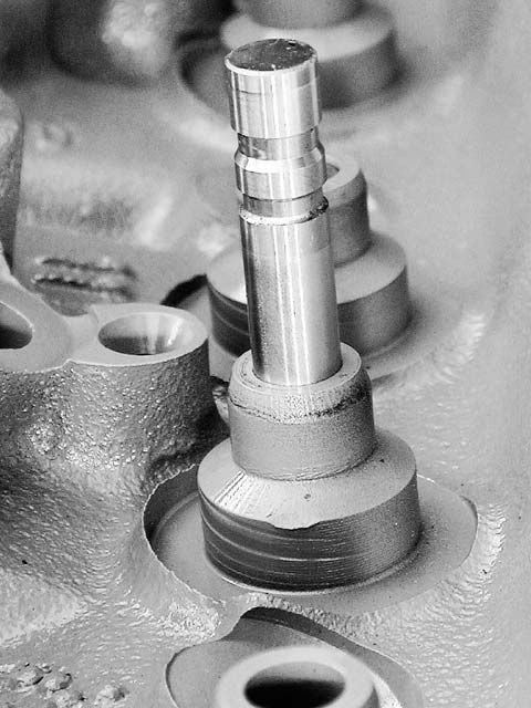
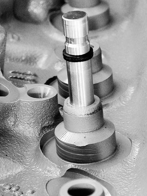
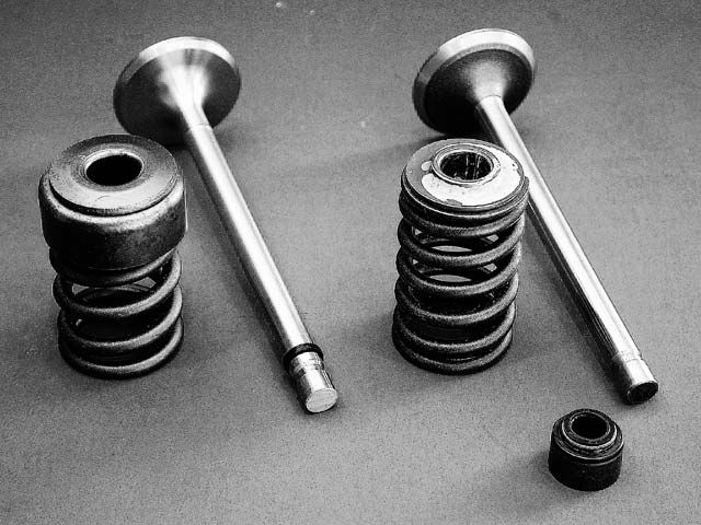
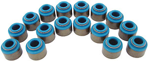
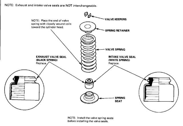
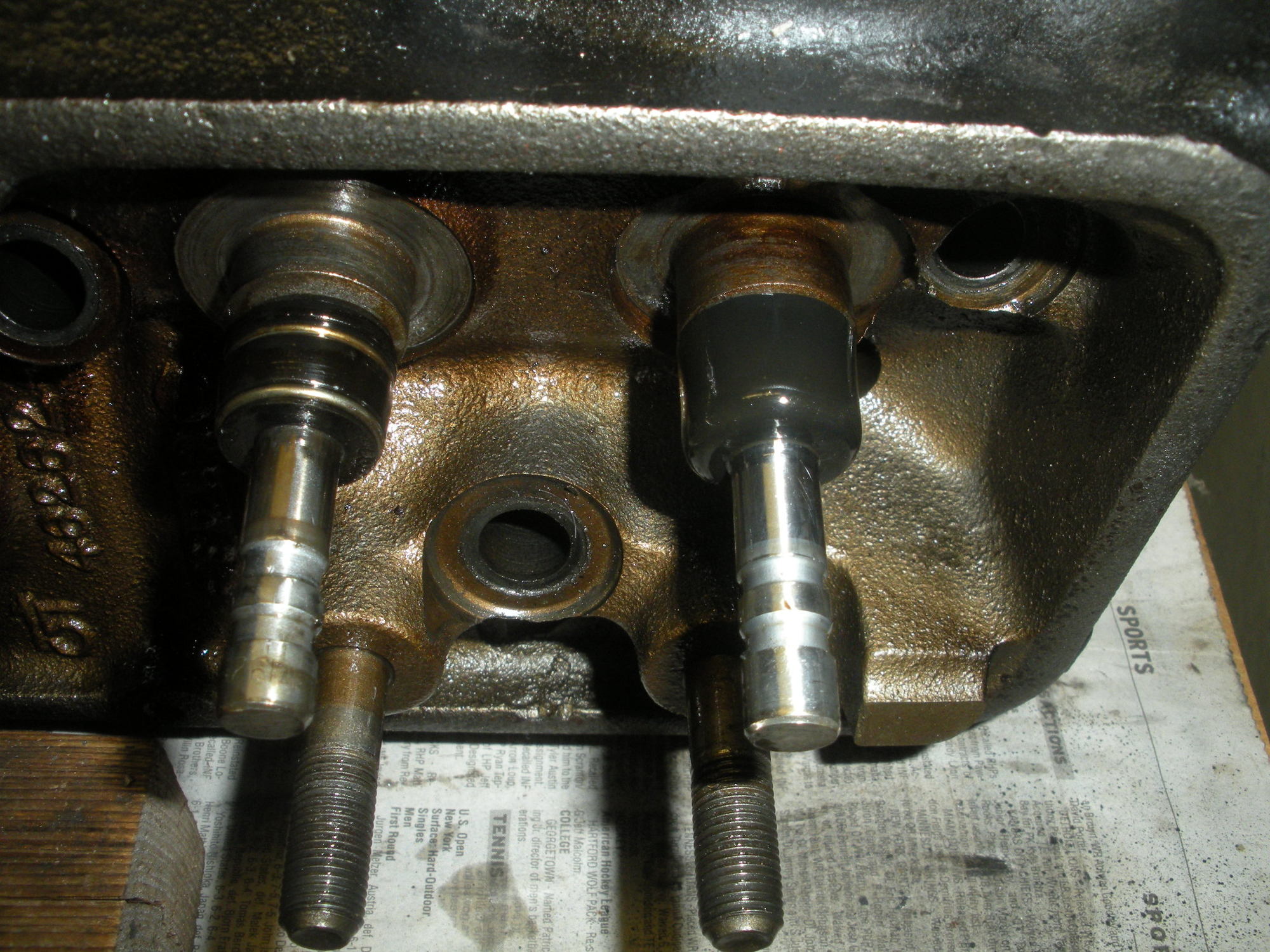
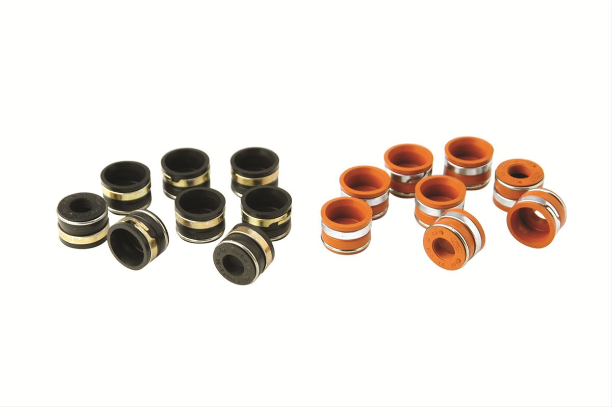
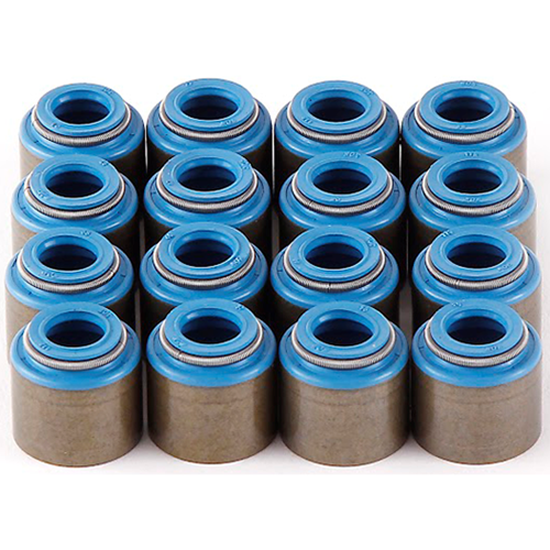
The intake and exhaust seals are different, because the intake can see a high vacuum, but the exhaust doesn't, but oil can seep into the exhaust. You can see why the exhaust seals are called "umbrella" seals.
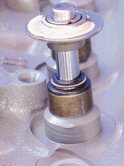
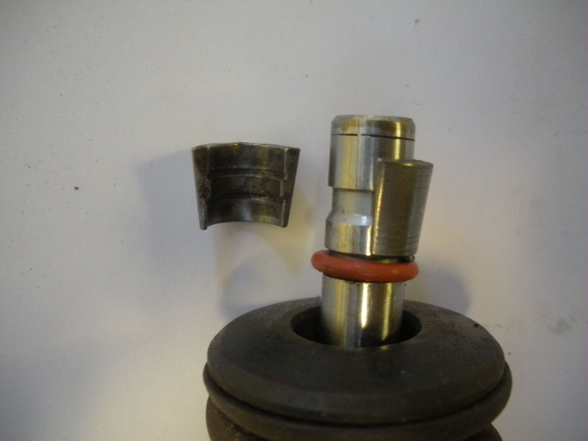
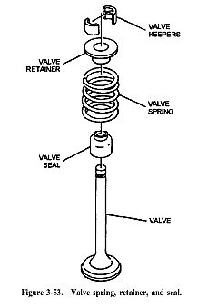
There are also seals inside the valve spring retainers, that fit into the bottom groove of the valve keeper area.
Use a magnetic tool to hang onto the little keepers, since you'll have the spring compressor in the picture, unlike the above photo! Keep track of which spring goes where. The exhaust springs have "valve rotators" in our engines.

