* Danny Cabral/Holley EFI manual Said:
Tuning the Knock Sensor Parameters
Knock sensors are designed for use on a factory engine and vehicle. When these sensors are installed in a non-original engine and/or vehicle, the user must be aware of the following:
· Adjustment of the knock sensor parameters may be required such that the ECU can properly distinguish between an actual knock condition, and a non-knock condition. This process is described below.
· Items such as mechanical (solid) cams may introduce noise frequencies into the engine that may inhibit the proper operation of the sensor.
http://mtg-technologies.com/automotives ... 456288.htm
Knock sensors are a device that output a signal to the ECU. This signal contains a spectrum of many different frequencies. The purpose of a knock sensor is to output a signal in a specific frequency range when knock occurs such that the ECU can recognize a knock condition. The signal when knock occurs should have a much larger amplitude (strength) compared to when knock does not exist. This is how the ECU properly determines when knock is and is not occurring. This requires that the proper frequency be input by the user for the specific sensor and application.
There are two basic types of knock sensors: a “Resonant†sensor (which has one wire) and a “Non-Resonant†sensor (which have two wires). Most newer vehicles use a Non-Resonant sensor. These sensors serve the same purpose, but function very differently.
· A 1-wire resonant sensor typically is designed for an intended knock signal frequency. It is affected by the specific engine, chassis, and installation as well.
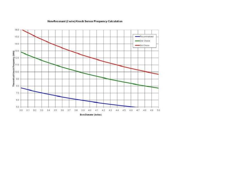
· A 2-wire non-resonant sensor has a knock output frequency that is primarily driven by the bore diameter of the engine. A chart is provided below to provide the user with a calculated starting frequency.
Setup Parameters
The following Parameters must be set in the software for knock sensors:
Type: Choose from either “1 wire†(Resonant) or “2 wire†(Non-Resonant) sensors.
Number: Select if the engine has 0, 1, or 2 sensors present.
NOTE: If you are not using any knock sensors, make sure you select 0.
Frequency: This is an adjustable parameter. If this value is not the correct value for the specific sensor and application used, engine knock will NOT be detected. It is imperative that this value be entered properly. Information for setting this is below.
Sensitivity: This parameter is used to adjust the scaling of the knock sensor signal. If false knock is being detected, it should be lowered. If actual engine knock is NOT being properly detected, this value can be raised. Start with a value of 50.
“Knock Level†Parameter: The Knock Level parameter can be found in the data monitor and data logger. It is a key parameter when monitoring and tuning knock control. This is a value from 0-100. This value is a reading of the magnitude of the knock sensor output in the frequency range selected. If this value reaches “80†and above, the ECU will read this as a knock event and perform timing retard. Values below “80†are not seen as knock.
Initial Frequency Recommendations
Non-Resonant Sensor
The following table is used to input a baseline knock sensor frequency for a NON-RESONANT (2-Wire) sensor. The “Recommended†selection is the line that you want to use to determine a starting point. The “2nd Choice†would be a second selection if for some reason the recommended frequency does not offer the desired outcome. The “3rd Choice†values can also can indicate knock, but the signal is not as large as the other choices and is typically not used.
To determine the frequency, find the bore diameter in inches for you engine at the bottom of the page (X axis), move up to the “Recommended†line (blue). Move to the left to the Y axis and find the corresponding frequency.
For example, a 5.7L LS1 engine has a bore size of 3.90 inches. This would result in a Theoretical Knock Frequency of 6.0 kHz.
This table offers an excellent starting point for a Non-Resonant sensor. However, tolerances in components and differences in each application may require adjustments.
http://i41.photobucket.com/albums/e300/dcf150/Kn oc...
Resonant Sensor
The proper frequency for a Resonant (1-wire) sensor is mostly dependent on the sensor design itself. The engine and chassis also can alter the best frequency selected. So it is required to find this information in a service manual or other source if a Resonant sensor is used.
The following is a recommended starting point for two common GM Resonant 1-wire sensors:
AC Delco PN 213-3521, GM PN 12589867 – Commonly used on 1998-2006 GM LSx engines. Baseline Frequency – 11.1 kHz
AC Delco PN 213-324, GM PN 10456288 – Used on Late 80’s GM engines. Baseline Frequency – 5.2 to 6.5 kHz
“Tuning†the Knock Sensor Settings
The following is the recommended process for testing and setting proper knock parameters.
1. Per the recommendations above, set the knock sensor parameters.
2. Make sure the base timing table is calibrated such that you will have no knock at any RPM and load. Set the Max Timing Retard in the ESC parameters to 0.
3. Drive the vehicle and take a data log. Record at idle, cruise, and WOT. Look at the following parameters on a data log:
Knock Level
· RPM
· MAP
· TPS
· Ignition Timing
4. Review the log. You specifically want to look at the Knock Level parameter. It should never be over 80. If it is (and you didn t actually have real/audible engine knock), you need to lower the â Sensitivity value until all non-knock conditions result in a Knock Level below 80. When properly adjusted, a WOT knock level value should be around 20-50. Idle may be 0-10.
5. Once the Sensitivity is adjusted properly for non-knock levels, enter Max Timing Retard Values of 20 (or whatever your preference is).
6. To check for proper knock retard, the ignition timing can now be advanced to a level that induces knock. When knock occurs, the Knock Level should exceed a value of 80 and knock retard should occur. If knock occurs and the knock level is below 80, the Sensitivity is not adjusted properly or the Frequency is not correct.
NOTE: Inducing knock can harm your engine. If you are testing the sensor response by inducing knock, be VERY careful. If your vehicle is too loud to hear audible knock, be very careful. You do not want to operate an engine under a prolonged knock period. Damage can occur immediately in some engines.
7. If the Frequency and Knock level are properly set, the knock retard will respond appropriately and remove timing until the knock is eliminated.
yes you can set lifter pre-load with experience while the engines cold, but in my experience the chances of doing it correctly if your rather new to the process is low.
if you set the lifters on a non-running engine you may find that you need to go back and do it again once the engines been run awhile, this is almost mandatory in my experience.
that knock sensor myth, youll occasionally hear about that says roller rockers can,t be used because the computers knock sensor won,t allow roller rockers, on the Lt1 and LT4 engines, got started because many people can,t correctly adjust valves, especially if your using roller rockers
they leave too much slack in the valve train (usually due to adjusting the valve train while its cold and not adjusting the hydraulic lifter pre-load correctly) and as a result the slight ticking that results is detected as detonation.
once correctly adjusted theres no need to swap knock sensors
Tuning the Knock Sensor Parameters
Knock sensors are designed for use on a factory engine and vehicle. When these sensors are installed in a non-original engine and/or vehicle, the user must be aware of the following:
· Adjustment of the knock sensor parameters may be required such that the ECU can properly distinguish between an actual knock condition, and a non-knock condition. This process is described below.
· Items such as mechanical (solid) cams may introduce noise frequencies into the engine that may inhibit the proper operation of the sensor.
http://mtg-technologies.com/automotives ... 456288.htm
Knock sensors are a device that output a signal to the ECU. This signal contains a spectrum of many different frequencies. The purpose of a knock sensor is to output a signal in a specific frequency range when knock occurs such that the ECU can recognize a knock condition. The signal when knock occurs should have a much larger amplitude (strength) compared to when knock does not exist. This is how the ECU properly determines when knock is and is not occurring. This requires that the proper frequency be input by the user for the specific sensor and application.
There are two basic types of knock sensors: a “Resonant†sensor (which has one wire) and a “Non-Resonant†sensor (which have two wires). Most newer vehicles use a Non-Resonant sensor. These sensors serve the same purpose, but function very differently.
· A 1-wire resonant sensor typically is designed for an intended knock signal frequency. It is affected by the specific engine, chassis, and installation as well.
· A 2-wire non-resonant sensor has a knock output frequency that is primarily driven by the bore diameter of the engine. A chart is provided below to provide the user with a calculated starting frequency.
Setup Parameters
The following Parameters must be set in the software for knock sensors:
Type: Choose from either “1 wire†(Resonant) or “2 wire†(Non-Resonant) sensors.
Number: Select if the engine has 0, 1, or 2 sensors present.
NOTE: If you are not using any knock sensors, make sure you select 0.
Frequency: This is an adjustable parameter. If this value is not the correct value for the specific sensor and application used, engine knock will NOT be detected. It is imperative that this value be entered properly. Information for setting this is below.
Sensitivity: This parameter is used to adjust the scaling of the knock sensor signal. If false knock is being detected, it should be lowered. If actual engine knock is NOT being properly detected, this value can be raised. Start with a value of 50.
“Knock Level†Parameter: The Knock Level parameter can be found in the data monitor and data logger. It is a key parameter when monitoring and tuning knock control. This is a value from 0-100. This value is a reading of the magnitude of the knock sensor output in the frequency range selected. If this value reaches “80†and above, the ECU will read this as a knock event and perform timing retard. Values below “80†are not seen as knock.
Initial Frequency Recommendations
Non-Resonant Sensor
The following table is used to input a baseline knock sensor frequency for a NON-RESONANT (2-Wire) sensor. The “Recommended†selection is the line that you want to use to determine a starting point. The “2nd Choice†would be a second selection if for some reason the recommended frequency does not offer the desired outcome. The “3rd Choice†values can also can indicate knock, but the signal is not as large as the other choices and is typically not used.
To determine the frequency, find the bore diameter in inches for you engine at the bottom of the page (X axis), move up to the “Recommended†line (blue). Move to the left to the Y axis and find the corresponding frequency.
For example, a 5.7L LS1 engine has a bore size of 3.90 inches. This would result in a Theoretical Knock Frequency of 6.0 kHz.
This table offers an excellent starting point for a Non-Resonant sensor. However, tolerances in components and differences in each application may require adjustments.
http://i41.photobucket.com/albums/e300/dcf150/Kn oc...
Resonant Sensor
The proper frequency for a Resonant (1-wire) sensor is mostly dependent on the sensor design itself. The engine and chassis also can alter the best frequency selected. So it is required to find this information in a service manual or other source if a Resonant sensor is used.
The following is a recommended starting point for two common GM Resonant 1-wire sensors:
AC Delco PN 213-3521, GM PN 12589867 – Commonly used on 1998-2006 GM LSx engines. Baseline Frequency – 11.1 kHz
AC Delco PN 213-324, GM PN 10456288 – Used on Late 80’s GM engines. Baseline Frequency – 5.2 to 6.5 kHz
“Tuning†the Knock Sensor Settings
The following is the recommended process for testing and setting proper knock parameters.
1. Per the recommendations above, set the knock sensor parameters.
2. Make sure the base timing table is calibrated such that you will have no knock at any RPM and load. Set the Max Timing Retard in the ESC parameters to 0.
3. Drive the vehicle and take a data log. Record at idle, cruise, and WOT. Look at the following parameters on a data log:
Knock Level
· RPM
· MAP
· TPS
· Ignition Timing
4. Review the log. You specifically want to look at the Knock Level parameter. It should never be over 80. If it is (and you didn t actually have real/audible engine knock), you need to lower the â Sensitivity value until all non-knock conditions result in a Knock Level below 80. When properly adjusted, a WOT knock level value should be around 20-50. Idle may be 0-10.
5. Once the Sensitivity is adjusted properly for non-knock levels, enter Max Timing Retard Values of 20 (or whatever your preference is).
6. To check for proper knock retard, the ignition timing can now be advanced to a level that induces knock. When knock occurs, the Knock Level should exceed a value of 80 and knock retard should occur. If knock occurs and the knock level is below 80, the Sensitivity is not adjusted properly or the Frequency is not correct.
NOTE: Inducing knock can harm your engine. If you are testing the sensor response by inducing knock, be VERY careful. If your vehicle is too loud to hear audible knock, be very careful. You do not want to operate an engine under a prolonged knock period. Damage can occur immediately in some engines.
7. If the Frequency and Knock level are properly set, the knock retard will respond appropriately and remove timing until the knock is eliminated.
yes you can set lifter pre-load with experience while the engines cold, but in my experience the chances of doing it correctly if your rather new to the process is low.
if you set the lifters on a non-running engine you may find that you need to go back and do it again once the engines been run awhile, this is almost mandatory in my experience.
that knock sensor myth, youll occasionally hear about that says roller rockers can,t be used because the computers knock sensor won,t allow roller rockers, on the Lt1 and LT4 engines, got started because many people can,t correctly adjust valves, especially if your using roller rockers
they leave too much slack in the valve train (usually due to adjusting the valve train while its cold and not adjusting the hydraulic lifter pre-load correctly) and as a result the slight ticking that results is detected as detonation.
once correctly adjusted theres no need to swap knock sensors
Last edited by a moderator: