Component Selection & Design for 500 HP Fuel System

On the supply side ....

Since I have established the supply side up to the firewall, I went back to re-make the aluminum
fuel line in SS 1/2 inch SS fuel line. Since I have a pattern to use now, I hope to duplicate the fuel
line SS. Easier said than done !!! I did document the bend in degrees of 67°. Even thou I had a
bend degree scale on my bender, I still compared to my pattern, a few degrees off would be easy.
But it does give a starting place.

FP04_SupplyLineShutOffToPump_00131.jpg

I made a hose to go from my Holley fuel pump to the filter. I tried to make it about 1/16 inch longer
than measured, not to bad. When you have such short lines like I have between the fuel tank and where
it goes inside the frame, the lengths are critical. If you have a line that is in feet, then this would be
much easier, you could be off by a up to 3/16 inch with no problems.

The shorter the line the more critical the measurement will be !!!

FP04_PumpToFilter-BraidedHose_00133.jpg

FP04_PumpToFilter-BraidedHose_00136.jpg
 
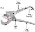
Sorry to say the Rigid Tubing Cutter PC-1375 would not even cut 1/2 way thru the Summit hose with
the SS internal braid. I even took the cutting blade out and sharpened it, but it didn't help. I tried
on plain 3/8 inch fuel line and it was still difficult. When I went to Home Depot to purchase the Rigid
tool, I was surprised that the handles were so short, not much leverage.

RigidTubingCutter(PC-1375).jpg

https://www.homedepot.com/p/RIDGID-...-Stroke-PVC-and-Tubing-Cutter-23493/202056531

.
 
the pictures look impressive your obviously doing nice work,

are you trying to cut the fuel line strait through with mechanical force,
or are you installing the heat shrink tube and rotating the tool 360 degrees several times,
while applying constant firm pressure?
(btw a spray of wd40 lube oil, seems to help the tool rotate and cut, try it on scrap first, to get the hang of keeping the cut strait and not a spiral)
 
Finally I'm ready to install the 1/2 return line down the right side frame rail. Not enough room to get a drill motor into place so I'm using the Mag Daddies that you see in the photos. Had to run to local family owned hardware store, they have the best selection of SS fasteners. I needed some short 1/4-20 SS bolts to close the SS 1/2 inch Adel clamps.

Took a couple of hours to get everything polished and cut about 3/16 inch of the bolts you see in the photos.

The 5 feet of SS return fuel line with have NO bends, this will be important to run it between
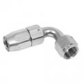
all the other frame brackets in the way. On the front will be AN-8, 90° hose fuel line bend
that will lead to the pressure regulator.

FP01_HoseFitting_90°_SUM-220887N.jpg

In the rear will be a 45° bend if I run braided flex line
or it could be more of the 1/2 inch SS line and it will incorporate the 45° bend. We will see
just how confident I feel about bending SS line.

There will be more photos of the INSTALLED returned line that will help make the above
statements clearer.

FP05_FinishedFuelLineSupport_00148.jpg


Any body need a Mag Daddy, I seem to have plenty !!!
I used 4, so there are 36 extras !

FP05_FortyMagDaddies_00146.jpg

.
 
.
Making more progress on the fuel system. I've got the return line completed.

FP06_HoseFittingComponentsSeparated_00149.jpg

FP06_HoseFittingNut_00151.jpg

I found it to be plenty easy to get the hose inside of the nut, no special tools needed. You can see below
how the hose butts up against the shoulder where the threads start.

FP06_HoseInNut_00153.jpg

FP06_HoseFittingAssemblyVaseline_00156.jpg

FP06_AN_HoseAssembly_00158.jpg

One hose end is complete

FP06_AN_HoseAssemblyComplete_00159.jpg

I have a complete hose ready to go from the SS return line up to the fuel tank.

FP06_CompletedHoseReturnLineOutput_00163.jpg

Made sure I had everything on the SS line, Tube Nut, Sleeve and 3-Adel Clamp before flaring the last end. The clamps can
be put on after flaring, but it just easier to do it before.

FP06_FlaringReturnLineOutput_00162.jpg

FP06_ReturnLineOutput_MagDaddy_00169.jpg

FP06_ReturnLineOutput_00170.jpg


I will be interested to see if the MagDaddy fasteners stay where I put them.

.
 
.

And the flexible braided line from the pressure regulator to the SS return line.

FP06_MagDaddyFront_00167.jpg

FP06_ReturnLineRegToLine_00165.jpg

AN Fitting Tip:
By using the Nickel plated fittings, if there was ever a scratch in the plating it would not be
noticeable. Put a scratch in a black anodized fitting and the aluminum underneath would be
very shinny and visible.

.
 
Last edited:
well it looks a great deal like your making progress
 
A big part of the fuel system project is the SS line that run from the left frame rail at the firewall
to the carburetor, photos will make this obvious. With bends in more than one plane it gets
complicated. I have to align with both ends, frame rail and carburetor inlet, a few degrees off
will make a difference and put stress on the carburetor inlet.

I measured my aluminum line and added another 1.5 inches, then I cut my SS line to 29 inches.
Before I put any bends in the line, now is the time to polish it. Much easier to polish a straight
line than a multi-bend line. All thou when I bent the line, it made it look like it was frosted. So I
had to do some touch up after it was completed.

FP07_FuelLineStartingComponents_00179.jpg


You can see how I'm trying to follow my pattern, which is the aluminum line I've been using for 3
years now. Each bend should be 30°, if you can picture the bell housing, then at each bolt is a 30°
change until I get to the top of the bell housing. From there it's time to head to the carburetor.

FP07_FuelLineHalfFinished_00180.jpg

Each bend required me to insert the line for a test fit, many times for just one bend. In total I probably
had that line in/out maybe 15-20 times.

The fuel line in position. Don't be confused by the mirror image against the polished SS firewall. I have
trouble working down in that area sometimes, it truly is like working next to a mirror. I've tried several
times to tighten the wrong image. ;)

FP07_TopViewOfFuelLine_00183.jpg

Every time I cut the line it would leave an inner lip that I would remove with a Rat Tail File. It was
not that smooth after the cut and file, so I would polish the inner lip with the buffer. The same wheel
as I used for the outside. This would fill the first 5-6 inches with compound and require a flush with
Berryman B-12. The whole reason was to make the flared edge smooth and give me a nice flare. See
the next 2 photos to compare.

FP07_FuelLineCut_00186.jpg
FP07_FuelLineImproved_00191.jpg


The SS line just needed a small tweak, so I put it in the vise and applied a small force to make
everything align.

FP07_FuelLineBendTweak_00184.jpg


The completed 1/2 inch SS fuel line.

FP07_FuelLineFinishedOnBench_00193.jpg

Much too close for comfort, the excess was slightly less than one inch.

FP07_FuelLineExcess_00199.jpg


To flush the lines I used the plastic AN caps and carburetor cleaner. Then I used my Heat Gun to
heat the line. The plastic caps were compatible with the carb cleaner.

FP07_FlushLineChemtool_00202.jpg

.
 
both amazing quality work, and impressive photo skills! WOW!
 
Just wish I could get you up to the year 1999 median standards. Who cares about a decade or two,
besides you have your abacus in your bag of tricks!

AbacusCalutor.JPG AbacusCalculatorGrumpy.jpg
 
.
I've had the fuel system pretty much finished this winter except flushing the lines, both SS and
flexible. Today I decided to bypass the carburetor and pressure regulator and then run the fuel
pump with the 10 micron filter in place. So all I needed was a temporary line to go from the carb
inlet direct to the return line. I already had the aluminum line I used to feed the carb from the
driver frame rail. It was just too easy to twist it around to mate up with the other lines. To make
it work I added a couple of 90° fittings at each end (Nickle Plated).

Now all I have to do is run the new pump for 5-10 minutes and let the 10 micron filter capture any
debris left inside the system. I hope to do that this week, just might take some vacation. I still have
to install the fuel tank/beer keg, then I can do the flush.

FP08_FuelSystemFlush_00536.jpg

FP08_FuelSystemFlush_00537.jpg

.
 
I did the first filter change since installing the Aeromotive 10 micron filter above. The filter has
2200 miles on it and any debris from when I flushed the system after installing and before
connecting to the carburetor. See above for my bypass for the carb.

No particulates in the bottom of the canister.

FP01_FilterChange_1055.jpg

I never opened the filter housing before the installation, so below is what you see from the
manufacturing process when I wiped the inside of the outside canister.

FP01_FilterChange_1056.jpg

There have been some changes in the filter, such as internal o-ring material and filter
construction.

FP01_FilterChange_1057.jpg

FP01_FilterChange_1064.jpg

FP01_FilterChange_1065.jpg

Looking at the filter media under good lighting and 8x magnification I did spot some
debris occasionally, but this would include trash from when I flushed the system right
after assembly.

FP01_FilterChange_1070.jpg

FP01_FilterChange_1067.jpg

This is what I'm using for inspection at 8x magnification. It was used for inspecting film when
cameras used such a thing. I take my pics thru this eye Lupe.

FP01_FilterChange_1071.jpg
 
Gotta Replumb the Fuel system in the Trans Am.
Need #10 & #12 AN Race Teflon lined Stainless Braided hose.
Expensive.
For 1000+ Hp Emergency Power On.
 
RICK! I LOVE the high quality photos detailing the project progress!
 
Back
Top