Electrical Wiring for a TBucket

echo 4 9er where did you get that pic of my dash grumpy. So I got a little carried away and about training the wife to read them well lets just say after I bought all those gauges I didn't have money for the sensors. But they make me really feel like I am flying. I plan to convert to airplane controls next. The pulling back on the stick will apply the lock up in the trans. And also guys just wait till I get the rocket power ejection seats out of an old mig installed it's gonna be sweet.
 

If you look closely, I think you will agree it's not as nice a dash as you
originally thought??? ;)

vettegage.jpg
 
Last edited:

You shouldn't sit back and not comment even when you don't agree, that's one
reason why I post is to get comments. I try to keep an opening mind, but in the
end I have to do what I think is best.

I don't comment when i disagree on forums unless it concerns safety or someone asks for opinions.


I agree with that it would be easier and faster to use a wiring harness from one
of the major manufactures, but I won't learn as much.

The major reason for not using a harness is all the extra circuits like Radio,
Windows, Lighter ...... that I will not use. Then what do you do with that wire,
I guess you could remove it. I also wanted finer control over what each circuit and
fuse for the circuit would consist of. The journey is just as important and arriving
at the final destination for me.

If the major reason for not using a harness is because of extra circuits then just buy a minimal harness kit however if the real reason is just that you want to build it yourself then just do it yourself. It usually takes me 40-60 hours to rewire a muscle car using a kit from AAW, Ron Francis etc. depending on how many modern upgrades there are like electric cooling fans, aftermarket ignition, aftermarket gauges etc. It would probably take double or triple the time if I had to make the fuse block/harness as well. Have you ever made a wiring board?

I'm tempted to just use a crimp it would be much faster to just crimp. But it sounds
like you think soldering is better than just crimping, so why would you want anything
less for the other connections that don't involve the CPU???

Because a very, very small increase in resistance won't affect the performance of most components. There's simply no real benefit and every soldered connection takes time. I solder battery cable connections and anything where a computer is involved in sending/receiving info that affects changes in fuel, timing etc. The only car I've had to do much soldering on recently (other than custom battery cables) is the Factory Five GTM project with an ISIS system in it.

The clock is for the wife so she won't have to go looking for the phone and like you
say I have time on the Speedo.

Happy wife = happy life! Do it!

Why would you swap the Speedo and Tach, is it normally the opposite of my drawing.

Because while driving your eyes tend to look down and right more than left. The speed info is more important than a tach for a car driven on the street. The tach gets used for tuning and for shifting at the best possible moment during racing. On the street we rarely need to look at the tach, we shift by instinct and the sound of the engine.


A bit about me:
I'm the underachieving son of a brilliant Umass/MIT educated electro optical engineer who designed and received patents inventing things like dual wave filter CO2 sensor instrument which prevented a recurrence of the Apollo 1 disaster, the laser/reflector that allowed us to determine exactly how far away the moon is, laser reconnaissance cameras and many other military electro optical instruments that may still be classified. Dad taught me how to splice and solder wires correctly around 4th grade and progressed to Heathkit projects beginning with a crystal diode radio and progressing. I'm sure I was the only kid on the block back in the 60's with an oscilloscope on the work bench in our basement ahahaha. I never really liked math and avoided it whenever possible so that pretty much ended dads hopes of me following in his electrical engineering footsteps.

Dad built a TV from scratch back in the 50's because they were new and very expensive. When I asked why he didn't build a color one when they came out and we bought one at a store he explained that he already knew the principles of how it worked and they were affordable enough so that there was no real reason to build one. He could spend the time learning something else rather than spending the time on labor building one. I try to remember that I don't need to build things just because I can and that it's often better to just buy a product that saves me time. This way I have free time to spend on the internet ahahaha!

Here's a thread with a LOT of info and links to suppliers etc. on car wiring for those who are interested http://www.corner-carvers.com/forums/sh ... hp?t=34419
 
yes and I find that it always helps to assume every new person you meet can POTENTIALLY teach you a few things , so its best to read several threads they post until it becomes obvious the skill and experience level they have, and I find that at least a significant percentage of the more experienced guys ARE willing to answer questions and spend some time teaching , if your reasonable in posing questions, which is a HUGE help to those who read the threads later.
 

[NOT A TA]
Because a very, very small increase in resistance won't affect the performance of most components. There's simply no real benefit and every soldered connection takes time. I solder battery cable connections and anything where a computer is involved in sending/receiving info that affects changes in fuel, timing etc. The only car I've had to do much soldering on recently (other than custom battery cables) is the Factory Five GTM project with an ISIS system in it.

[Rick]
I see your logic. It only matters when you have a very large current, then the
voltage drop is big also.

-------------------------------------------------------------------------------------------------------------------

[Rick]
Why would you swap the Speedo and Tach, is it normally the opposite of my
drawing.

[Not A TA]
Because while driving your eyes tend to look down and right more than left. The speed info is more important than a tach for a car driven on the street. The tach gets used for tuning and for shifting at the best possible moment during racing. On the street we rarely need to look at the tach, we shift by instinct and the sound of the engine.

[Rick]
Is there some science behind your statement? I do see your point and believe
you are correct. That might be a change I will make.... Thanks!!!


[Not A TA]
A bit about me:
I'm the underachieving son of a brilliant Umass/MIT educated electro optical engineer who designed and received patents inventing things like dual wave filter CO2 sensor instrument which prevented a recurrence of the Apollo 1 disaster, the laser/reflector that allowed us to determine exactly how far away the moon is, laser reconnaissance cameras and many other military electro optical instruments that may still be classified.
Dad taught me how to splice and solder wires correctly around 4th grade and progressed to Heathkit projects beginning with a crystal diode radio and progressing. I'm sure I was the only kid on the block back in the 60's with an oscilloscope on the work bench in our basement ahahaha.

[Rick]

I would to see a picture of that, it would be funny !!! :lol:
I lusted after that big stereo receiver kit from Healthkit. Healthkit was in my
wife's home town of Benton Harbor or St Joseph Michigan.

[Not A TA]
Dad built a TV from scratch back in the 50's because they were new and very expensive. When I asked why he didn't build a color one when they came out and we bought one at a store he explained that he already knew the principles of how it worked and they were affordable enough so that there was no real reason to build one. He could spend the time learning something else rather than spending the time on labor building one. I try to remember that I don't need to build things just because I can and that it's often better to just buy a product that saves me time. This way I have free time to spend on the internet ahahaha!

[Rick]
I wonder how we ever got along without the internet, it makes things so much
easier and fun.

[Not A TA]
Here's a thread with a LOT of info and links to suppliers etc. on car wiring for those who are interested http://www.corner-carvers.com/forums/sh ... hp?t=34419

[Rick]
I've read the first 3 pages far, it's a lengthy thread and extends over a period
of a couple of years.

Here is a few more threads with some good info for those that are reading:

http://www.chevelles.com/forums/showthread.php?t=300744
http://www.colorado.edu/physics/Educati ... iring.html
http://www.rbracing-rsr.com/wiring_ecu.html
http://doanfamily.net/blog/


Please do post when you have some thoughts concerning the subject matter,
good or bad I would like to consider your point of view !!!!


grumpyvette said:
yes and I find that it always helps to assume every new person you meet can POTENTIALLY teach you a few things , so its best to read several threads they post until it becomes obvious the skill and experience level they have, and I find that at least a significant percentage of the more experienced guys ARE willing to answer questions and spend some time teaching , if your reasonable in posing questions, which is a HUGE help to those who read the threads later.

You're spot on here Grump. At least in my case, I often look back at previous posts forum members have made. I frequent several forums and after a while you start to know who's knowledgeable and who's reciting things they've heard or read rather than speaking from actual experience.

Also, knowledgeable folks are less likely to respond in threads unless all the information needed to form a good response is provided. There's nothing more annoying than playing question and answer for days. I rarely answer posts where someone doesn't provide sufficient information when they ask for help. I pass right over a question like "I replaced my BBC with a SBC and now it overheats, anyone know why?" . It just gets tiresome trying to pull all the details needed from the OP.
 
There are other advantages to soldering crimped battery cable ends. People tend to be pretty rough with battery cables because they're thick, the soldering increases the mechanical bond. How many times have we seen frayed battery cables where the terminal is from the twisting action people use installing/removing. It also fills voids where corrosion starts so (in theory) it should last longer.
 
grumpy said:
it has become rather obvious to me, after watching my neighbor try to repair his older muscle cars under dash wiring, that many guys have no concept of how to correctly make a wire splice repair so i figure I WILL post the basics here. yeah watching guys who think twisting a bit of wire together and covering it with electrical tape or using a couple wire nuts is the correct way to splice wire is about to make me a bit more insane than I already am.
TOOLS YOULL NEED

BE AWARE THE WIRE GAUGE AND RELAY AMP RATES VARY SO SHOP CAREFULLY
http://www.aliexpress.com/item/10pcs-Ca ... 80067.html
http://www.harborfreight.com/127-piece- ... 67524.html
http://www.harborfreight.com/127-piece-heat-shrink-tubing-set-67524.html
grumpy said:
nplkj.png


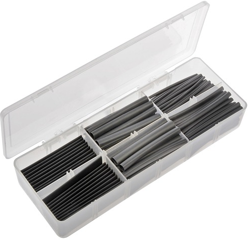
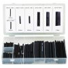
Just a tip when using shrink tube, as a protective cover,
over wires leaving an electrical socket or sensor,
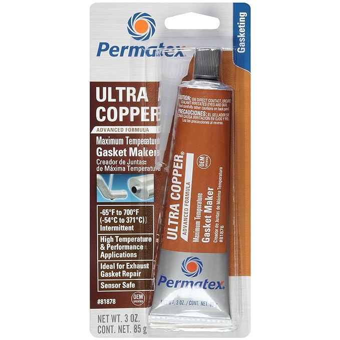
Ive generally found adding some silicone sealant,
918eL3jcP5L._SX679_.jpg

on the electrical connection to wire exit areas, to the area the shrink tube covers is a good idea to further reduce moisture damage

http://www.oreillyauto.com/site/c/detai ... &ppt=C0335

http://www.nelcoproducts.com/heat-shrin ... MgodIj8AzQ

http://www.alliedelec.com/search/produc ... U=70113992

http://www.harborfreight.com/42-piece-m ... 67598.html

http://www.harborfreight.com/120-piece- ... 67530.html

http://www.harborfreight.com/127-piece- ... 67524.html
I can,t believe the number of times I use this insulation rubber shrink tube sections ,to make electrical splice repairs so it makes a great deal of sense to buy in the larger package sizes as you get 5-7 times as much tube for less than 3 of the smaller blister packs contain

http://www.cabletiesandmore.com/america ... -p-636.php
http://www.cabletiesandmore.com/america ... -p-638.php

http://www.cableorganizer.com/wire-loom ... eloom.html
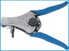
a DECENT QUALITY WIRE STRIPPER

http://www.bing.com/shopping/weller-wel ... ORM=CMSPEE
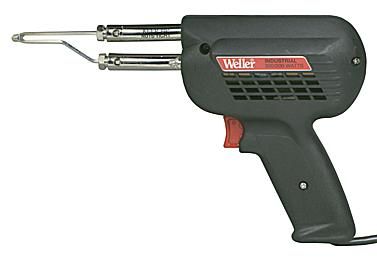
anything under about 200 watts in an electric solder gun,rating is basically a P.I.T.A. to use and a TOY in my opinion simply because you cant quickly bring the wire and solder up to the correct temps, a 250-300 watt solider gun makes doing the work far easier
solderinggun.jpg

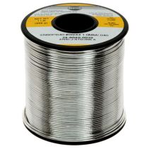
good 60/40 lead/tin solder
http://www.bing.com/shopping/4-oz-40-60 ... ux&FORM=EG
solderv.jpg

http://www.radioshack.com/product/index ... d=12582872
fluxz.jpg

flux.jpg


READ THRU THIS LINK
http://www.aaroncake.net/electronics/solder.htm

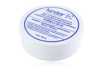
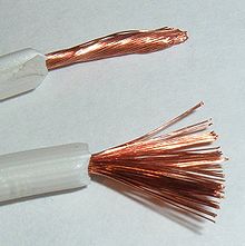
the process is rather easy and simple top do with practice, assuming the standard 14ga-12 ga under dash wiring ,you simple strip off about 1.25" of insulation on each end of the two wires, larger ga wire will require a longer section, of insulation be removed, once thats done you spin the stranded wire end between your fingers
220px-Stranded_lamp_wire.jpg

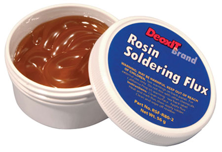
to twist it tightly so it won,t leave exposed copper wire ends and then slide on a 2.5" to 3" long section of heat shrink tube , (don,t forget to do this) now dip both the twisted copper wire ends in the solder flux, then twist them both together tightly in a spiral so they won,t easily separate, now add a dab of flux because much of its most likely been removed during the twist process but if you don,t do it before you twist its not going to get full coverage on the strands.
ok ideally you,ll have decent access and have the shrink tube slid on the lower wire so it won,t slide down while you solder, use the tip of the heated solder gun on the far side of the two twisted wires and touch the solder to the near side as it heats allowing the fluxed surface to draw the solder once its liquid over and around the spliced copper wire surface, once its well coated pull the solder and solder gun away , it the surface is well coated and smooth silver in appearance you can let it cool a bit then slide on the heat shrink tube , center it over the spice and use the heat from the tip of the solder gun placed near too ,but never touching, and while smoothly moving the guns tip so as not to over heat or burn the shrink tube until it firmly shrinks and hugs the spliced and soldered copper wire, making the soldered splice at least semi protected, the shrink tube, acts as insulation and a corrosion protective barrier , BTW a bit of BEES WAX can be heated and melted over the ends of the shrink tube where it joins the original insulation and used as a increased effective,moisture barrier.

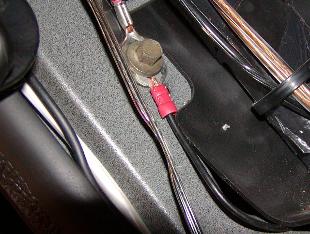
btw youll eventually be tempted to use crimp connectors or wrap wire around a screw connector on a sensor or electrical component
crimpcon1.jpg


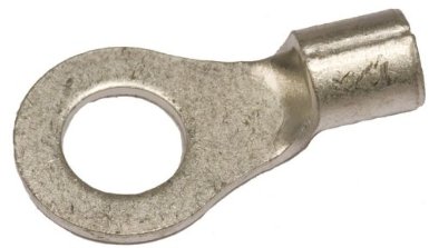
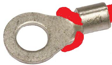
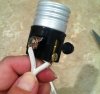
do your self a big favor and use ring end connectors
ringend.jpg

but here again SOLDER THE CONNECTOR TO THE WIRE LIKE THIS, AND SLIDE ON SHRINK TUBE INSULATION LEAVING ONLY THE RING END EXPOSED ITS FAR LES LIKELY TO CAUSE PROBLEMS
ringendw.jpg


10 ga wire should be all thats required

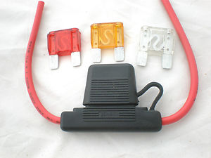
theres are 60 and 80 amp 12-14 volt relays with pig tails, or places to connect ring terminal connectors available, its common for high capacity fans to draw 35-40 amps at times, so using a 60-80 amp relay and the required minimum fuse amp rated circuit sure won,t hurt

ampm1.jpg


ampm2.JPG


ampm3.gif

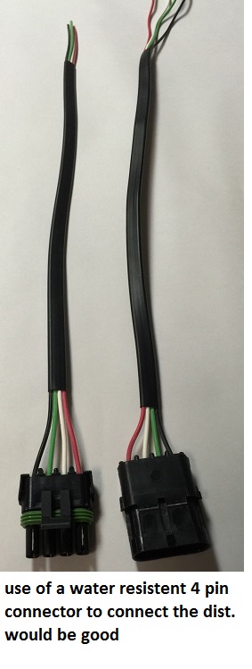
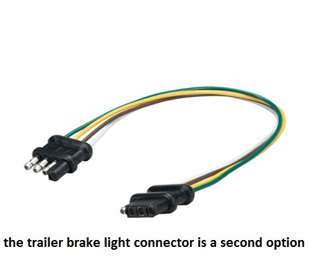
use of and taking the time and effort, when building or repairing the wiring on any custom car, to install a $5 -$7, UNIQUE for each electrical component , quick connect indexed water resistant screw-up proof, male/female connector combo, that allow's you too quickly connector remove a distributor or other component from the cars wire harness and re-install it with little chance of screwing up the electrical connections is almost always a good idea

4pinwe.jpg

4pinwe1.jpg


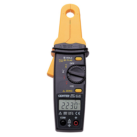
obviously measuring the current draw would help here
http://www.ecutool.com/DT-337-Mini-ACDC ... _7294.html

viewtopic.php?f=70&t=3504&p=33365&hilit=solder+ring#p33365

http://www.ebay.com/itm/Heavy-Duty-Auto ... 0375347709

http://www.wiringproducts.com/contents/ ... relay.html

http://www.jegs.com/i/Derale/259/16738/10002/-1

http://www.cableorganizer.com/wire-loom ... eloom.html

http://www.technooutlet.com/viac025.htm ... 1b2166c62d
 

Attachments

  • crimpcon2.JPG
    crimpcon2.JPG
    17.3 KB · Views: 17
  • shrinktube1.jpg
    shrinktube1.jpg
    26.8 KB · Views: 17
  • wirestripper.jpg
    wirestripper.jpg
    11.6 KB · Views: 17
Last edited by a moderator:

Been trying to do my planning and research before I do something drastic like
rip out all the old wiring.

Developed this overall drawing showing the whole car, so I can see where I need
to route wires. Later I will break it down to circuits and start drawing the actual
wires.

_WiringDiagram01.jpg
_WiringDiagramCenter01.jpg

I've even listed the exact color wires coming out of my steering column. When I
had it apart earlier I found OEM tags and did some research, it looks like it from ....

Steering Column from a 1967-1969 Ford F-100 thru F-350 Truck.
Carolina Classic’s website said it fits 1963-1969
13341-C, BPD, C50A

SteeringColumnOEM_Documentation_5097.jpg

Still looking for a wiring diagram that fits my wires and their colors.

_WiringDiagramSteeringColumn01.jpg
SteeringColumnWiring&ColorCodeActual.jpg

In my Excel file I'm trying to list EVERY DEVICE and what circuit it will be in.
More than one circuit can run thru one device, so when you see text in light
gray, then it must be listed again in it's main circuit. Then I'm taking every
circuit listed across the top and breaking it out into it's own list with more
details.

Excel_ComponentList.jpg
Excel_BasicPowerBreakout.jpg

 
Last edited:

I did find this circuit diagram, but it does not fit my colors exactly.

I highlighted the circuit that would go thru the steering column to see if I could use it.

SteeringColumnWiring&ColorCode.jpg

Sorry I left it big so it would be readable later.

 
Last edited:
Rick I alway love seeing your posts I get ideas, allot of them are already there but you either add to them or helping me decide certain things. Plus I like how you are organizing your plan of attack.
 

Thanks John, I'm needing some motivation right about now. I've yet to to put a
single wire in a drawing, I'm feeling overwhelmed, not having ever done this
before. I'm trying to follow my own advice ..... how do you eat an elephant, one
bite at a time. I just need to start with one wire and then the next and so own.

Maybe today!!! :?

 
I feel your pain between having to cross that bridge and the EFI conversion stuff my head is going a million directions but feel I will take a little ou of the OEM play book break it down into smaller systems which also makes trouble shooting easier. More time spent on paper and triple checking your work will pay off three times over when it's all systems go time.
 

Ok, I jumped on that elephant and started eating !!!

I need everyone's eyes on these circuits that I draw. There is bound to be
some mistakes. Please let me know if you see anything questionable !!!

Power&ChargingCircuitDrawingVer01.jpg

I combined the first two circuits into one drawing. The dyno sheet from
Power Master shows the max current to be 475 amps for the starter. The
cutoff switch will need to be rated for at least 475 intermittent amps. Also
per Power Master the switch will need to be rated for maximum alternator
output once the engine is running. So in my case that would be about 175
of continuous amps rating.

It took me all afternoon to do this. I created all but two of the symbols and
determined where every line could attach to the symbol. For example the
fuse panels have an attachment point for lines at all 12 fuses, 6 at the ground
bus or 3 each side, one for the positive line and one for the negative line in.

I don't know how I could have done this without Microsoft Visio, although I'm
sure there must be some others out there. Visio has a great feature that
when you have to move a symbol, all the wires will move with it. Can you
imagine how many times you have to adjust the placement of the symbols......
many, many, many times. It would drive me nuts to redraw the lines every
time. It also creates the jumps across the wires that do not connect.

At this time the photo below is the Blue Sea Systems 5031 fuse panel that I
plan to use, it's for marine use. One for the "Switched Circuits" and one for
the "Always On Circuits" for a total of 24 circuits. I won't need that many, but
I will have plenty of room to grow.

$41.18 each
http://www.amazon.com/dp/B001P6FTHC/ref ... A1D1SH5924

BlueSea_5031_Photo.jpg

 
Last edited:
Strictly Attitude said:
:D Looking good so far I have something very similar on graph paper

Just don't think I would have the required patience for graph paper. Just too
many changes on my part.

Many Kudos to you!
 
Back
Top