Electrical Wiring for a TBucket

Indycars

Administrator
Staff member

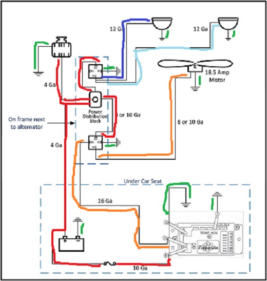
I'm trying to get ready for the new alternator from Brian, so I have created a
electrical drawing for the alternator and fan circuits. I want to make sure I'm
wiring it correctly and therefore buying the correct components. Eventually I
want to completely rewire the whole car from scratch or maybe buy a wiring
harness from someone like Painless, Autowire or Rebel.

I need to place and order soon, since I have off the week between Christmas
and New Years. Hope to get some real work done that week.

I most want feedback on whether the pieces are connected correctly, don't want
to burn anything up. Also the wire gauge sizes, are they correct???

Fan&Alt_Circuit.jpg


Below is the wiring diagram out of the Flex-A-Lite installation manual.

FanController-FlexALite.jpg

Any feedback or comments is greatly appreciated guys !!!

 
Last edited:
almost everything looks great but Id make a couple changes,
your ability to draw that out and post it is amazing!

now obviously this is only a suggestion based on some experience in building race cars and you can ignore it , but Ive always felt that simple is better.
please ignore my sub standard computer skills here!
If it was my car Id color code all the wiring to make future trouble shooting far simpler
Id use only 10 ga wire no thinner gauge wire, I like the idea of not making things difficult or confusing

BE AWARE THE WIRE GAUGE AND RELAY AMP RATES VARY SO SHOP CAREFULLY
http://www.aliexpress.com/item/10pcs-Ca ... 80067.html

http://www.offroaders.com/info/tech-cor ... wiring.htm
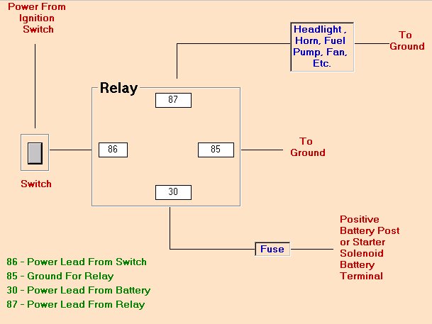
85 and 87a -> Ground

86 -> Power

30 -> Output

-30 = constant [positive (+)] power (usually wired directly to car battery)
-85 = coil ground (wired to the negative (-) battery terminal or any grounded metal panel in the car)
-86 = coil power (wired to the control source. could be a switch, or it could be the car's IGN or ACC circuit.)
-87 = switched [positive (+)] power output. (when the relay coil is powered, lead/pin 87 is connected to lead/pin 30)
-87a = [on 5 lead/pin relays only] this lead/pin is connected to lead/pin 30 when the coil is NOT powered.
relaywire.jpg


Id color code all direct ground connections green
all direct power battery positive leads red
both HEAD LIGHTS a different shade of blue
fan lead orange
ID use a label maker to print out a label for each wire connection
READ LINK

viewtopic.php?f=50&t=6098&p=18837&hilit=label+numbers#p18837
Fan&Alt_Circuita.jpg
 
Last edited by a moderator:

I've looked into creating custom line colors in Microsoft Visio, but have not
got there yet. No matter how the drawing looks, I do plan on having many
different colored wires in the actual wiring harness. Your idea about only
using 10 gauge might actually save money since I would not have to buy
100 ft of 7 different colored wires of 12, 14 and 16 gauge wire. Those three
sizes would cost roughly $300.00 for the GXL crossed link wire spools. That's
actual prices from Del-City wiring. I had already decided not to use any 18 gauge
wiring, which would work for some things.

http://www.delcity.net/

 
Last edited:
thanks I went and fixed that over site, on that linked post

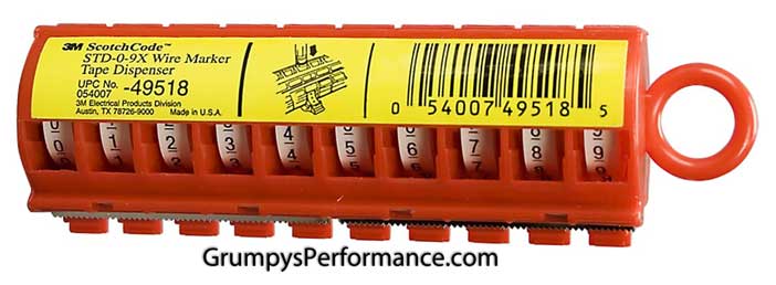
btw I found those pre-printed, fold-able plastic tape, number tags , on a dispenser rather useful for marking relays, and spark plug wires

and having a label printer handy while you wire the car has some advantages

labelprint.jpg


http://www.staples.com/Label-Makers/cat_CL90400

http://www.brother-usa.com/Ptouch/Ptouc ... uucKfLcSCk

https://www.cableorganizer.com/shrinkflex-shielded-2-1/
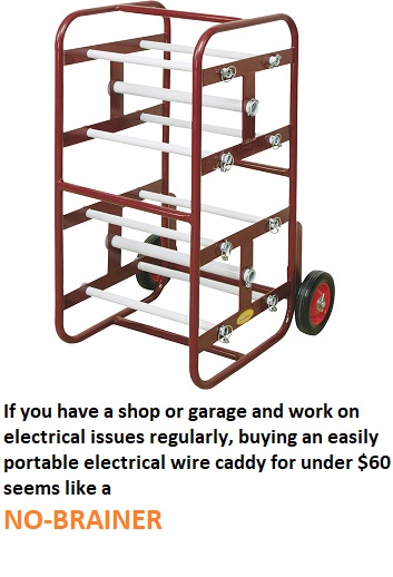
THIS IS A GOOD VALUE
163443.jpg


https://www.northerntool.com/shop/t...MIq4Gj3qeW2AIVVrXACh3l2QRxEAYYCCABEgK4afD_BwE

3M sells these really handy number tape tags

12174a.jpg


Distributors:

Depending on the year of your TPI engine will depend on the type of distributor that was used. In 1985-86 "F" body (Camaro-Firebird) and 1985-1991 "Y" Body (Corvette), the distributor was the familiar looking large cap HEI distributor. Upon closer examination of the original distributor you will see it's cap is held down by 4 screws. The more common HEI distributors, if you have another 1974-86 small block Chevy to compare, is held with 4 latches. Another difference is the 4 wire EST connector to the wiring harness. While the common HEI has the prongs with two outer slots facing up, the HEI used on the TPI engines, has one of these slots facing to the outside.

You can use the common HEI on your TPI for the years mentioned above, but you will have to swap the connector at the harness or find the connectors at a salvage yard, which can be found on the 1985-86 3.8L V6 found on the FWD vehicles or on the 4.1L V8 Cadillac motors.

lg_HEI_2.jpg


Shown above is the large cap HEI distributor, this one is the common variety which the cap is latched instead of being held by four screws. These can have the est connector modified to work on your TPI engine perfectly.

The next distributor was on the 1987 through 1992 Camaro-Firebird TPI engines. This is what I call the "small cap" HEI, which uses a remote mounted coil, typically is bolted to the intake manifold. You will note this is the time period, Chevrolet switched to the roller cam motor, and this distributor was used on these engines.

sm._HEI.jpg


Shown above is the "small cap" HEI with coil.

coil_and_wiring.jpg


The remote coil has two connectors. The gray connector is the 12V coil power supply, the large pink wire goes to ignition "on" power for the distributor, the white wire can be hooked to a tachometer. The black connector has the smaller pink and white wires which goes to the two wire connector on the ignition module on the distributor.

distributor_conn..jpg


EST connectors that send the ignition signal back to the ecm, The one of the left is for the "small cap" HEI, the center one is for the "common" large cap HEI, note the two outer prongs with slots facing up. The connector on the right is the "TPI" distributor connector (1985-86 only), used with with screw down caps. Note one prong with slot facing up, the prong on the far left has a slot but is facing towards the left.

tbi-tpi_distributor_compare.jpg


Be careful in pulling a small cap HEI to use. The distributor to the left is used on the 1987-1992 Camaro/Firebird. Note the smaller base as compared to the distributor on the right, these larger base distributors were used on some 1991-1993 "B" body TBI equipped engines, such as the Chevy Caprice and Buick Roadmaster. They use the TBI throttle bodies which are held down with two studs for the air cleaner, and the manifolds are machined for the large base distributor they use. They will not interchange.

DISTRIBUTOR GEAR APPLICATIONS

There has been a lot of controversy concerning the interchange of the distributors using a large cap HEI on a 1987 and later block and using a small cap distributor on earlier blocks. It used to be on the safe side, use the large coil in cap HEI on the pre-87 blocks and the smaller remote coil HEI on the 1987 and later engines. Now with the aftermarket coming to the rescue for those who want to use the different distributors due to firewall clearance issues, availability, etc. it is possible to use the distributor of your choice, but you must use the proper distributor gear based on the material the cam distributor gear is made of.

Crane cams makes the proper distributor gears for the roller and non-roller blocks.

General rule is to use a bronze alloy gear for a steel distributor gear on the camshaft (most factory roller cams follow this route). For an cast iron cam use a irondistributor gear (all non roller cams and some later aftermarket roller cams use an iron distributor gear on camshaft.

Crane cams does make a coated steel distributor they say is superior to the bronze alloy gear with a OEM life span. It can be found at this URL through Jeg's performance parts: http://www.jegs.com

Part # 270-11951-1

Coated Steel Distributor Gear
Chevrolet
90° V-6 1978-86, 200 thru 262
V-8 1955-87, 262-thru 400 .491'' Dia. shaft
V-8 1965-90, 396 thru 502
  • .491'' Dia.
Crane also makes a iron gear that fits the small HEI distributor for use in an earlier non-roller cam application.

Part# 270-11970-1

Iron Distributor Gear
Chevrolet
90° V-6 1985-91, 262 For GM HEI
V-8 1985-99, 305-350 For GM HEI .427'' Dia. shaft
V-8 1991-00, 454-502 For GM HEI
If you want to use the bronze alloy gear it is part # 270-11988-1 for the small HEI (.427" dia. shaft)

For the large HEI it is part # 270-11990-1 (.491" dia. shaft)
 
Last edited by a moderator:

I found this label machine by Dymo that prints directly on heat shrink tubing. The
down side is you have to buy their heat shrink tubing. But it would just as easy to
just use clear heat shrink and put it over the printed label using standard materials.

Cost on Amazon is $74.32 with shipping included.
http://www.amazon.com/dp/B005MR516Y/ref ... HNYMEF8XGA

DymoImage.jpg
DymoMaterials.JPG

It has plenty of symbols and different materials that might be convenient when
doing wiring.

DymoSymbols.JPG


Watch a video about the Dymo 4200 below.

http://www.dymo.com/en-US/online-suppor ... ew-video-p

 
Last edited:

I've studying up on electrical wiring for automotive systems by readying everything I can find on the internet and also bought two books by Tony Candella. He also has a website where he sells many of the components he talks about, including the relays and connectors for waterproof conditions.

SA209Electrical Project.jpg SA160ElectricalSystems.png


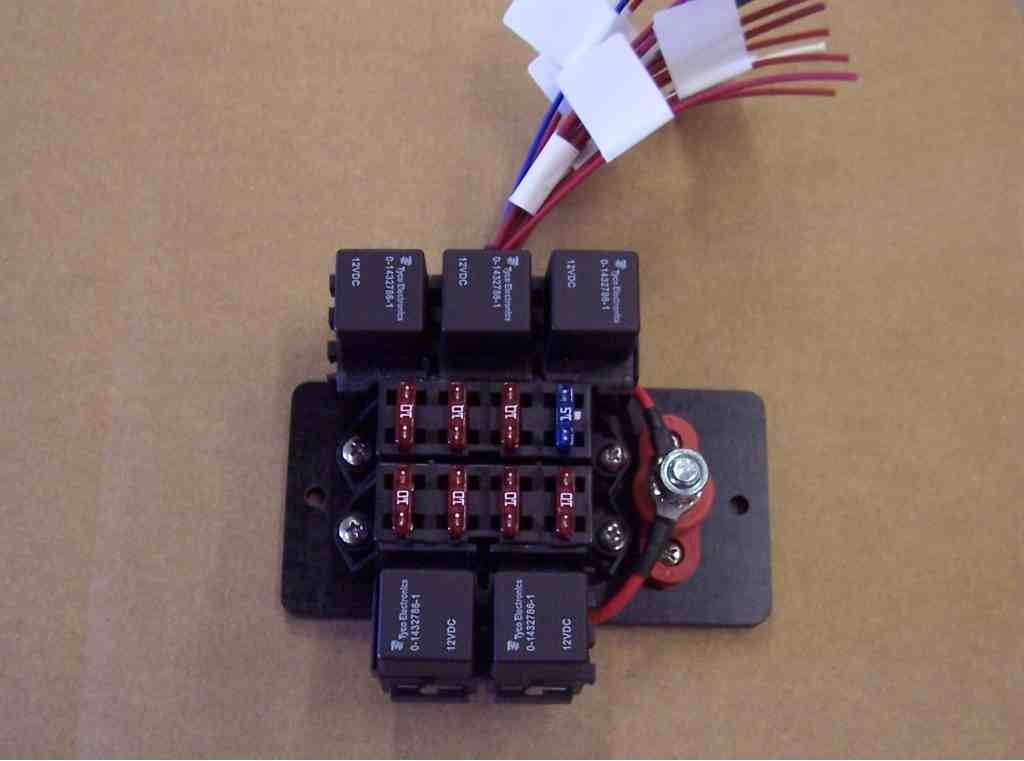
Considerable money can be saved by going elsewhere. I bough supplies for three relays, connectrs and terminals. I will have to add my own 10 gauge wires for the power connections, where most others only have 12 gauge pigtails for the power connections.

hellawprelay_sm.jpg

So bottom line it would have cost me $87 for three relays and connectors with pigtails. From Waytech I purchased the same thing for $38, the only difference is, I will have to add my own wires from the waterproof connector. Which means I will have to purchase a good crimping tool.

http://www.ceautoelectricsupply.com/rel ... noids.html
EC Electrical Components

wiredrelaysocket3_sm.jpg

Relay Specs with dimensions, I always need all the details I can get.

Waytek website
http://www.waytekwire.com/products/1401/Relays/

Hella Mini ISO Relay Specs.JPG

 
Last edited:

As I move forward with this project, I need to decide whether to CRIMP or
SOLDER my connections. Most likely it will be a combination of both. I always
believed before this project that it can't get any better than a soldered
connection, but after much research I can see where crimping connections
has it's place. At some point this can be terribly expensive purchasing
everything I needed to get started, so I will be soldering the big connections
larger than 10 AWG so I don't have to buy another crimper for a few cables in
my car that are that big. Anything smaller and I plan to solder when convenient,
like when I can do it outside the car on the bench.

First are the supplies that I have purchased. All the wire, ring terminals,
braided sleeving, tools and heatshrink is just general supplies that I need,
but the waterproof relays and connector are specifically for the headlights,
one for low beam and one for high beam, another for the Flex-A-Lite fan.
All relays are made by Hella and rated at 20/40 amps. That rating means
the relay is rated for 20 amps continuous on the Normally Closed (NC)
contacts and 40 amps continuous for the Normally Open (NO) contacts.

FP01_Purchase_Waytek_Relay&Connectors.jpg


http://www.amazon.com/Tool-Aid-18960-Ra ... ords=18960

Tool-ToolAidCrimper_18960.jpg

http://www.amazon.com/Klein-Tools-11063 ... ools+11063

Tool-KleinWireStripper_11063.jpg

Luckily I found a 15% off coupon for Del City, which saved me $65.

http://www.delcity.net/

FP01_Purchase-Del-City-Wiring01.jpg
FP01_Purchase-Del-City-Wiring02.jpg

http://www.wirecare.com/

I plan on putting labels under the clear heatshrink.

FP01_HeatShrink-CrystalClear.jpg

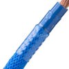
I don't like the looks of the corrugated plastic loom material, so I'm going
to use this braided sleeve material. Wire Care website sells nine different
types and most come in about 12 different colors.

Watch this video of the braided sleeve by TechFlex. It covers some other info,
but the braided sleeving starts at 2 min:05 sec.

FP01_BraidedSleave-TechFlex.jpg

Terminology was making it difficult about what's Open Barrel and Closed Barrel.
I had an idea, but I needed to know for sure. Also, how do you tell when you
have a GOOD crimp. The info below should help with terms and knowing when
to redo that connection.

FP01_Molex_Industrial_BarrelTypes.jpg

The next three graphics are just closeups of the page above so you can see
clearly what's being shown.

FP01_Terminals-ClosedBarrell.jpg
FP01_Terminals-OpenBarrell.jpg
FP01_Terminals-CrimpTypes.jpg

I would also suggest that you read thru this PDF, it's 27 pages long.
Yes I did read it all last night!
Ok, maybe I only read about 70% of it and skimmed the rest. I didn't
need to know how to crimp with a machine in a production environment.

http://www.molex.com/pdm_docs/ats/TM-640160065.pdf

And if you want to really ZOOM in, download the PDF file below.

Enjoy the reading guys !!! :p


Attachments

  • Molex_Industrial_BarrelTypes.pdf
    246.6 KB · Views: 1
Last edited:
wow!
I keep a rather extensive collection of wire ends, both crimp and solder style, and heat shrink tubes in various sizes and several rolls of different color 10 ga wire in the shop, some Ty-wraps ,and a couple wire strippers,crimpers and of course solder guns and solder and flux, but it looks like your going above and beyond! I vastly prefer soldered wire end connectors and heat shrink tube for most connections
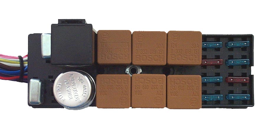
theres little sense in even having a relay in a car that won,t operate at a minimum of 12 volts and at least 30 amps minimum,
but Id have to point out that matched sets of relays and pigtails are readily available in several amp ranges rather cheaply.
once you understand how they are designed to function testing or replacing one is no
challenge


https://www.amazon.com/ARTGEAR-Harness-Color-Labeled-Automotive-Motorcycle/dp/B078T3RC5T

https://www.summitracing.com/parts/pco-5593pt/overview/

https://www.amazon.com/Fastronix-Weatherproof-Automotive-Relay-Socket/dp/B01CXA42XK

https://www.ebay.com/bhp/60-amp-relay

https://www.ebay.com/bhp/80-amp-relay

https://www.summitracing.com/parts/...MIq4ObtvSz3wIVU57ACh0MfQn4EAQYAiABEgJsYfD_BwE

https://www.amazon.com/dp/B07F83159...&pd_rd_r=991c9f49-060a-11e9-bb5a-dff16524fffe
RELATED THREAD
viewtopic.php?f=70&t=3504&p=33365&hilit=wire+crimp+solder#p33365

http://www.offroaders.com/info/tech-cor ... wiring.htm

http://www.jegs.com/p/Powermaster/Powermaster-GM-CS144-Style-Alternators/1534945/10002/-1

 
Last edited by a moderator:

I can't say that all crimped connection are gas tight, but at least some of them
when done right are suppose to be. Also the act of crimping breaks thru the
oxidation and creates a direct copper wire to connector electrical connection.

I did consider your suggestion of using all 10 gauge wire or larger. I just don't
have the room or hidden out of the way places to hide wiring that would be
bigger. It also, to a small extent, might help tracing a wire thru the loom if
it's different size next to other wires.

Maybe you noticed, I did not order anything smaller than 16 AWG.


Well I had a AH-HA MOMENT !
OhMyGod2.jpg

It finally hit me that hooking the Variable Speed fan controller to energize a
relay will NOT work as it should. Yes it will power the fan on, but only at full
speed and not the 60% of max to begin with.

The drawing in my first post in this topic, I run a 16 AWG wire from the Yellow
wire on the controller to the relay coil. I will have to run a 10 AWG wire from
under my seat where the fan controller is, to the Flex-A-Lite fan. Total length
should be under 6 feet.

FP06_FanControllerWiring01.jpg

 
Last edited:

I'm learning how to deal with this braided sleeve for wire management. It's certainly
not as easy as it looks before you get started. Making corrections, like removing a
wire and adding back another wire of different size is not easy. The damn stuff is
like a "Chinese Finger Trap". When I tried pulling a wire out, it just wanted to clamp
down even tighter. And it's never easy pushing a wire thru something, much easier
to pull it.

I had to have connectors, since I can't screw the sensor into the radiator while the
rest of the wire cannot rotate in the wiring harness. Anyway, below is the big picture.
Wires for temperature sensor will be hidden in the radiator shell, so to make this
easier, I staggered the connectors so they don't take as much room.

FP02_BraidedSleeve04_5020.jpg
FP02_TempSensorWiring_5028.jpg


This braided sleeve is suppose to be cut with a hot knife, so I used a box cutter
heated with a propane torch. But even then it would come apart while working with
it. So I will use heat shrink on every end of the sleeve to make it look neat and tidy.

The temp sensor uses 24 AWG, which is very fragile. It already came with it's own
black braided sleeve, but I put the red braided sleeve over both for more protection.
Again you can see that I staggered the connector to keep the package as small as possible.

FP02_BraidedSleeve01_5011.jpg

Having lots of different sizes of heat shrink is very helpful. I found some that was
just big enough to slip over everything, but still shrink down tight.

FP02_BraidedSleeve02_5013.jpg
FP02_BraidedSleeve03_5017.jpg


I used tape until I have the alternator and fan mounted, until then I can't know
exactly how long everything needs to be.

FP02_Harness_5026.jpg

 
Last edited:
its always BOTH a learning process and a P.I.T.A. at times to wire almost any custom built car electrical wiring but if you take notes and label things it will be fairly simple to trouble shoot and maintain
 
grumpyvette said:
its always BOTH a learning process and a P.I.T.A. at times to wire ......

I'm beginning to think I've met my match called wiring! But it's not just
wiring, it's the whole ball game.

What, When, and Where ... Then in which sequence do you put it to
all together???

No way have I've given up, just feeling a little frustration. :p

 
just break down the process into individual circuits and wire each individually , labeling each end of each wire as you go and use fuses and relays as required.
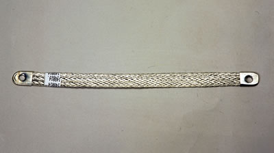
I generally start with a couple good chassis grounds to the engine and transmission and a third ground strap from battery NEG to the ENGINE, and a second battery neg strap to the frame.
if you break it down to individual well labeled circuits its not that confusing

viewtopic.php?f=36&t=317&p=13210&hilit=wiring+diagram#p13210

copst1.jpg

fzb1.gif

fzb2.jpg

fzb3.jpg

fzb4.jpg


sources for automotive wiring in rolls

https://www.wiringproducts.com/auto...MI7IrHy-Hn3gIV4f_jBx2UKQrlEAAYAiAAEgKktPD_BwE

https://www.delcity.net/store/Wire-&-Cable/r_IS1010?&mkwid=s5jFlx8hX&crid=82384381709&mp_kw=automotive wire&mp_mt=b&gclid=EAIaIQobChMI7IrHy-Hn3gIV4f_jBx2UKQrlEAAYASAAEgK-HfD_BwE

https://connectorexperts.com/?gclid=EAIaIQobChMI7IrHy-Hn3gIV4f_jBx2UKQrlEAAYAyAAEgIAkPD_BwE

https://bulkwire.com/

https://www.waytekwire.com/products/1453/Wire-Cable/

https://www.maneywire.com/wire-and-cable

https://www.awcwire.com/categorygroup.aspx?id=wire-and-cable

https://www.amazon.com/s/?ie=UTF8&k...hvtargid=kwd-449882953&ref=pd_sl_7ejajt3igf_b
fzb5.jpg
 
Last edited by a moderator:

I'm starting to smell Glyptal and alternator high temperature silver paint!!!

AlternatorShipping.jpg

Santa is almost here !!!!!!!!!!!!!!! :D

SantaClaus.jpg


Last edited:
:D

Just one wire off the Field connection plug turns on your alternator Rick.

Cover more when it gets to you Christmas Eve.
 
YES Rick.
The TRANSPO Regulator we used is not typical GM Specs.
No Resistor required. Connect in series with Idiot battery alternator llight bulb.
Or to switched 12Vdc power.
Transpo uses a special electronic regulator design all thier own.
Better than all.
Gold, Platinum, Diamond grade Aerospace electronics used.
Not Wally world Junk.
 
Crimp all electrical connections Rick.
Then Silver Solder.
Solder will Wick in.
Makes for lowest electrical conductive resistance connection possible.
PIA For newer Rodders.
Your old school too.
Must do the best always.
 
Back
Top