My Cam Research for the Experts Eye

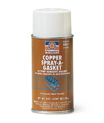
a good coat of copper coat spray helps gasket seal a great deal, read the links,


copperspray1.jpg


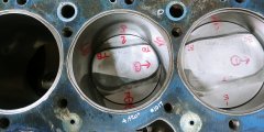
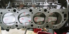
Here's the 4.520 gasket laid over the 4.28 bore

20220220_145301_HDR_resized.jpg

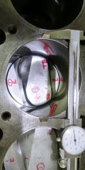
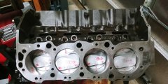
This is where the 4.37 gasket would lay over the 4.28 bore using a caliper. I don't have the experience to say 100% ok. Does this still look good?

20220220_145743_HDR_resized.jpg
 
Last edited:
The 4.37" bore gasket looks much better to me. That space where the gases are trapped between the head and deck don't get burned completely and contaminated the incoming charge. As long as the gasket does not extend beyond the deck surface and into the cylinder, but also does not provide a cavity by being too big, that is the best of both worlds.

But again that's me and how I like to do things. It will be trivial for most people !

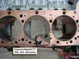
You can see how close I made the gasket. With copper I was able to trim it where needed.

GasketToBoreClearance_1925.jpg
 
thanks Rick, I also found this:


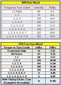
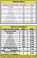
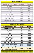
And more rotational data:

1645399072059.png
 
Your data looks more realistic when looking at going from from 1-4, to 1-5, I show 150 in/lbs both times and you show 144/180. I went back and looked at my data and it was recorded on two different days between 1-4 and 1-5. But I also have the same data when I go from 1-7 to 1-8, so surely I would not have made the same mistake twice. I've only made one mistake in my life .... I thought I was wrong, but I was right !!! :cool:

I'm not sure what to make of the our differences so far.
 
I'm not sure what to make of the our differences so far
Me neither lol. But the progression in the torque values on mine seem logical, will be interesting to see the increases as I get the short block assembled.

It looks like the 4.370-4.375 gasket bore will work, both on the block side and the chamber side. So now it's determining thickness and material. I don't think I'll use copper, looking at the MLS requirements of the Felpro/Cometic gaskets.
 
Me neither lol. But the progression in the torque values on mine seem logical, will be interesting to see the increases as I get the short block assembled.
It might come down to when you take your reading. If I take a reading of the torque value when a piston(s) reaches TDC or BDC then it's as if it's not even installed. Another words, the torque to turn IS NOT A CONSTANT THRU 360°. Your mission, if you should decide to accept it is to make us believe your system will take the average of a 360° revolution of the crankshaft.

.
 
I was thinking similar as I was checking readings, the reading would diminish a bit at TDC and BDC then pick up again as I continued to turn the crank. Made sense, but was only noticeable for the first couple of pistons. As I added pistons this went away and I got a pretty steady reading, or as steady as my manual turning could get. That also made sense to me since as you add pistons they won't be at TDC and BDC at the same time so the force needed "should" be more and more even as you progress.

I figured by taking at least 3 readings , each based looking at several rotations I could get what's probably a reasonable average of the torque. Plus, bigger picture, this is to see if there's an issue somewhere with a tight bearing, ring etc so if there was a slight variance that would I think be ok as long as the engine rotates without issue.

I noticed your same-value readings on your chart - seemed a bit surprising that as you added the resistance of another piston the reading didn't also slightly increase to reflect the added drag.

PS - Mission Impossible and The Saint are two of my all time favorite shows!
 
Last edited:
the 4.376 gasket in the pictures, looks closed to ideal than the 4.52 gasket
 
Thanks Grumpy.
Something just came to mind that relates to gasket thickness. I'm about to take the heads in to the shop.
Maybe I should wait on buying the head gaskets until I get them back. I expect at the least they will be resurfaced which might affect the gasket choice.
I think what I may do is after I get them back, install them with the old known thickness gasket to verify piston to valve clearance. I'll then know what new gasket thickness to buy to stay in the target quench zone.
I'd hate to buy gaskets and then find out the heads needed x amount of material removed, causing me to have to buy another set.
Is this a sensible idea?

In the meantime I'm going to talk to FP and Cometic tech to ask for their recommendation for my application.
 
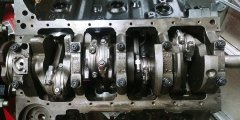
Last 2 pistons installed, everything went well. I'm satisfied that all ring top/bottom and gap orientations are good, rings turn freely and rods/caps are installed correctly, chamfers towards crank weights.

I think the overall rotational torque (and difference from Rick's block) is reasonable. Feels fine turning and I also verified that there are no ring scores in the cylinders - that compressor is great.

1645557726761.png

I will of course re-check torque on mains and rods.
ARP hardware:
Mains = 110 ft-lb
Rods = 63 ft-lb

20220222_123213_HDR_resized.jpg


20220222_123142_HDR_resized.jpg

20220222_122727_HDR_resized.jpg
 
Last edited:
It will be at least a week before further work, we're taking a quick trip to S. Texas next week before spring break madness and probably skyrocketing fuel cost.

I send this because of how much help you've offered and I don't want you to think I've disappeared.
:like:
 
Got back to it today. I've ordered some misc hardware such as ARP cam bolts, oil pump stud, etc. so further assembly will be whenever that stuff arrives. I did check out the valvetrain parts that came with the cam ....

Morel lifters
20220305_095739_HDR_resized.jpg

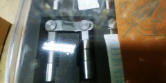
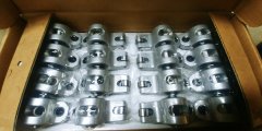
Harland Sharp roller rockers
20220305_095801_HDR_resized.jpg

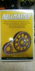
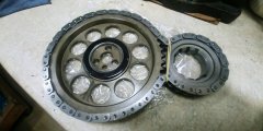
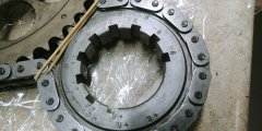
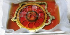
Rollmaster timing set with IWIS chain, torrington bearing
20220305_100729_HDR_resized.jpg
20220305_101153_HDR_resized.jpg
20220305_101316_HDR_resized.jpg

I set the chain/bearing into engine oil mixed with a bit of MMO
20220305_104605_HDR_resized.jpg

I mulled over whether or not to measure the torrington bearing thickness and replace with solid oil-impregnated thrust bearing of same thickness, but decided to go with the torrington. It's "installed" on the crank gear with 3 staked spots to retain it in place. My block does have both of the small front oil plugs that are drilled for lube to the timing set, so hopefully the torrington will last. It's not a good day if that bearing comes apart. If the advice here is to remove it and go with a solid thrust washer, I'll do that though.

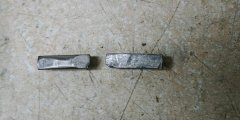
Installed new crankshaft keys - here are the old ones (top view), the one on the left was under the crankshaft gear and shows wear. One of those very simple things to replace with new.
20220305_102146_HDR_resized.jpg

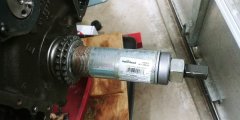
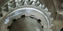
Used a proper balancer/gear installer to install the crank gear in straight up position per directions. I will degree the cam to ensure it's where it needs to be.
20220305_111537_HDR_resized.jpg
20220305_111958_HDR_resized.jpg

In the meantime I'm also working on the car electrical but keeping this thread as cam/engine related. Just a lot of other work going on in the background.

Cylinder heads are going to the shop next week, in the meantime I'll look up the info here on checking and setting up pushrod lengths.

As a start, I think I need that blue plastic rocker arm and I also found this:
Standard Length Big Block Intake 3/8" / .080" 8.275"
295-7941-8 Big Block Chevy, Standard Length Big Block Exhaust 3/8" / .080" 9.250"
295-7969-8 Big Block Chevy, Standard Big Block +.100" Long Intake 3/8" / .080" 8.375"
295-7979-8 Big Block Chevy, Standard Big Block +.100" Long Exhaust 3/8" / .080" 9.350"
295-7951-8 Big Block Chevy, Standard Length Big Block Tall Deck Intake 3/8" / .080" 8.675"
295-7961-8 Big Block Chevy, Standard Length Big Block Tall Deck Exhaust 3/8" / .080" 9.650"
295-7800 V8 396-454 Retro Fit Pushrod Set, Intake & Exhaust, 1965-Present
3/8" / .080"
3/8" / .080" 7.725 Int.
8.675 Exh


I take it that the retro fit info is for a retrofit roller cam installation.
It looks like I need a couple of pushrod length checkers to encompass 7.7" and 8.7"?
 
Last edited:
yes ...ITS darn cheap insurance to check & verify the valve train geometry,
and checking it certainly tends to avoid several potential related issues you might otherwise be dealing with
,
use of different brands of lifters and obviously use of roller lifters vs flat tappet lifters will result in the need for different pushrod lengths so you need to verify rocker geometry and valve train clearances


Last edited:
Thanks again Grumpy, yes I'll read through it all :thumbsup:

Just info, I am using threaded rocker arm studs with pushrod guide plates.

When I get my hardware, I'll get the timing set installed and degree the cam as next step, then install the oil pump (ensuring that stud doesn't contact the rear main bearing shell). I need to get the oil pan powdercoated asap so I can button up the bottom before installing the top end stuff. I really don't want to try to turn this beast on an engine stand with the cast iron heads installed!

One other item as I look ahead - I will static-set lifter preload, but I have a higher comfort level with also doing an actual running preload using an old set of cut-out valve covers. I think Summit has some cheapie stamped covers that I can cut to do this.
 
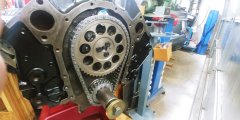
Timing chain installed, marks are with #1 at TDC. I also checked that the upper/lower timing gears were in the same plane and that the lower gear runs in the center of the links.
Everything turns fine, here's the readings I took. I'd say there's a 1-2 ft-lb variance just from the beam scale itself but these are fairly consistent over several readings. I also included Rick's Dart block readings as a general comparison, even though these are two different engines.

1647047308568.png

To measure torque needed to start rotation of complete assembly I slowly applied pressure to the beam scale until things started to move. I didn't try to "snap" start rotation because I think that reading would spike high.

20220311_151342_HDR_resized.jpg
20220311_151301_HDR_resized.jpg

ARP bolts are torqued to 25# per their spec but shouldn't I use a locking tab plate?
Edit - this is a Gen 6 stepnose cam that uses a retaining plate, I'm talking about the thin metal tab ring that you fold against the timing gear bolt heads. Don't seen to find for Gen 6.
 
Last edited:
Everything turns fine, here's the readings I took. I'd say there's a 1-2 ft-lb variance just from the beam scale itself but these are fairly consistent over several readings. I also included Rick's Dart block readings as a general comparison, even though these are two different engines.
Looks to be pretty much what one would expect when comparing these two engines.

shouldn't I use a locking tab plate?
If you can find one, it surely would not hurt to use one. I would use some RED Loctite on the 3 bolts, even with or without the locking tab plate.
 
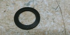
Since my post, I went back and looked at the timing gearset installation again. I didn't have red loctite but I had blue loctite so I used that, but I also used these serrated bellville washers under the ARP cam gear bolts. I could not find a locking tab plate. These washers are not Amazon knock-offs, they are Shnorr washers, oem supplier to most of the german car mfg. Excellent long-term quality, I've used them for years. I think that between the loctite, torquing to spec, and using the washers the bolts will stay in place.
20220313_121440_HDR_resized.jpg

Here's where I could use some additional input on my comments .... :)

1. The timing set fit is very snug, the bolts insert through the gear and into the cam no problem, but needs the bolts tightened to fully draw the gear fully onto the cam. I think that is ok. Too loose I think is a bigger issue for a brand new timing set, I anticipate it will very slightly stretch anyway.

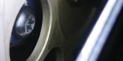
2. There appears to be space between the thrust plate retainer bolts and the gearset which of course is good (remember I'm using Gen VI stepnose cam), but I cannot move the cam either backwards or forwards. I think the cam is at its full forward position but if it goes backwards I don't know if this can be an issue with interference. I suspect this is because the new chain is pretty stiff. As mentioned, the assembly turns without any drama. The cam, retainer, retainer bolts and gearset were all supplied by Straub cams so I think if there's an issue they would not be supplied together on the same order. Retainer bolts are torqued to spec with blue loctite and the crank gearset is fully seated, verified by using a proper installation tool. So I believe that the timing set is in its "operating" position and if anything, the roller cam will want to push to the front vs a flat tappet cam.
20220313_122603_HDR_resized.jpg

3. Here's a look at a cam lobe with cam gear removed and cam pushed all the way forward against the retainer. Front of engine is to the right. The lobe is not dead center in the lobe. I don't know if this affects anything, my understanding is that the lobes are flat on roller cams. It would seem as long as the lifter rides close to center this would be ok?

20220313_122328_HDR_resized.jpg

4. Here's a look at the same lobe with the timing set fully installed. Virtually no difference so it's telling me that the timing gear is pulling the cam forward against the retainer. I will again double check that the crank gearset is indeed fully seated, but that should be fairly obvious?
20220313_121030_HDR_resized.jpg

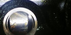
5. This pic verifies that the top gearset is fully seated onto the nose of the cam.
2132022133533.jpg

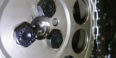
6. This picture is a bit murky, I'm trying to verify the relationship of cam retainer plate, cam, and torrington bearing. I need to examine this more closely. But what seems to be at this point is that the cam is in the full-forward position against the retainer plate and won't push backwards into the block, making me wonder if the bearing is actually even touching the retainer. I know that parts will seat in as the engine is run but I don't have the experience to know if what I'm looking at is ok or not.

20220313_122700_HDR_resized.jpg

EDIT - I'm adding this to highlight stopping to recheck things. I went back and used the crank gear/balancer installation tool to push against the crank gear again. Lo and behold the crank gear pushed in a bit further - evidently out of caution I had simply not applied enough pressure to actually fully seat the gear....
:facepalm:
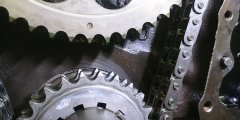
Using a straightedge against the top and bottom gears (the actual gear ring, not the face of the gears), the gears are in line and all turns smoothly.
I didn't get a picture yet but the bearing appears to be resting on the retainer plate, a slight difference from what looked like a gap before I re-pressed the crank gear.
The cam lobes appear to be in about the same place vs lifter bores - they didn't really shift backwards.
My reasoning here is that there was tension pulling the cam forward against the retainer. With now ensuring the crank gear is indeed seated, the tension has been reduced and gearsets are aligned.
I believe that this installation is now ok but I still ask about the lobe location within the lifter bore.
 
Last edited:
Back
Top