main cap studs, studs are NOT torqued into the block!
studs are screwed into the block for the full thread length then backed out 1/2 turn,
STUDS are installed through the main caps, before the nuts and washers are installed,
I generally oil the threads on the lower stud threads in the block,
but no loads are applied to the studs until the threads in the block are full length engaged,
into the block and the washers & nuts on the studs are tightened.
yes use
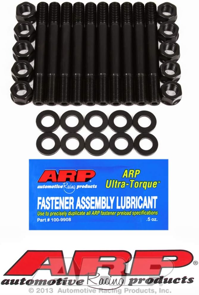
ARP Ultra-Torque fastener assembly lube on the threads.
on the main caps studs exposed fine threads, you use the nuts on.
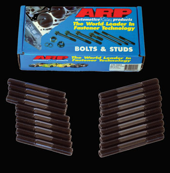
Serious race engine builders mostly use high strength ARP studs to anchor the main caps. Studs provide a more even clamping force with higher tensile strength than most bolts and they are less highly stressed in the block ...
hotrodenginetech.com
How to Install ARP Main Cap Studs
Serious race engine builders mostly use high strength
ARP studs to anchor the main caps.
Studs provide a more even clamping force with higher tensile strength than most bolts and they are less highly stressed in the block .
 1.
1. Clean and inspect ALL threads in the cylinder block thoroughly. After initial tank cleaning, dry the block and inspect threads closely. Chase the threads
with the appropriate size ARP thread chaser if necessary.
2. To prepare the threaded holes select a small stiff bristle nylon cleaning brush as found in engine brush kits available from online retailers.
We prefer to scrub the main cap bolt threads with a brush and brake cleaner and then blow them out with air to get them spotlessly clean prior to assembly. At this point you should also ensure that the main cap mounting surfaces are spotlessly clean and free of any nicks, burrs or other contamination. This step is important to ensure perfect seating of the main caps.
3. Clean and inspect ALL studs and verify all dimensions. Remove all shipping lubrication from the studs until they are squeaky clean.
4. Screw the studs into the appropriate holes HAND TIGHT ONLY! While not specified by the manufacturer,
we prefer to brush a very thin coating of ARP Ultra-Torque fastener assembly lube on the threads. Do not over-tighten the studs in the block.
Note: If permanent mounting of the studs is desired, Loctite may be applied to the threads.
If you do this the fasteners must be final torqued before the Loctite sets up.
 5.
5. Install the main caps and check for proper fit and alignment.
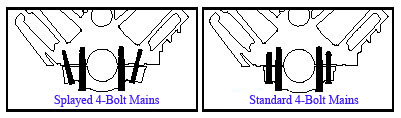
Splayed bolt main caps require outer stud installation after each main cap is installed.
Install the inner studs and use them as a guide for the main cap.
Tap the cap into place and then install the outer studs. (USE A DEAD BLOW MALLET)
6. Use a small application brush to coat the stud threads and washers with assembly lube and install the nuts finger tight.
Whether using
ARP fasteners or others,
we recommend ARP Ultra-Torque fastener assembly lubricant to ensure consistent torque readings.
Lubing with regular motor oil is discouraged due to inconsistent clamping forces. (THIS IS REFERING TO THE UPPER FINER THREADS< NOT THE
CORSER STUD THREADS IN THE BLOCK
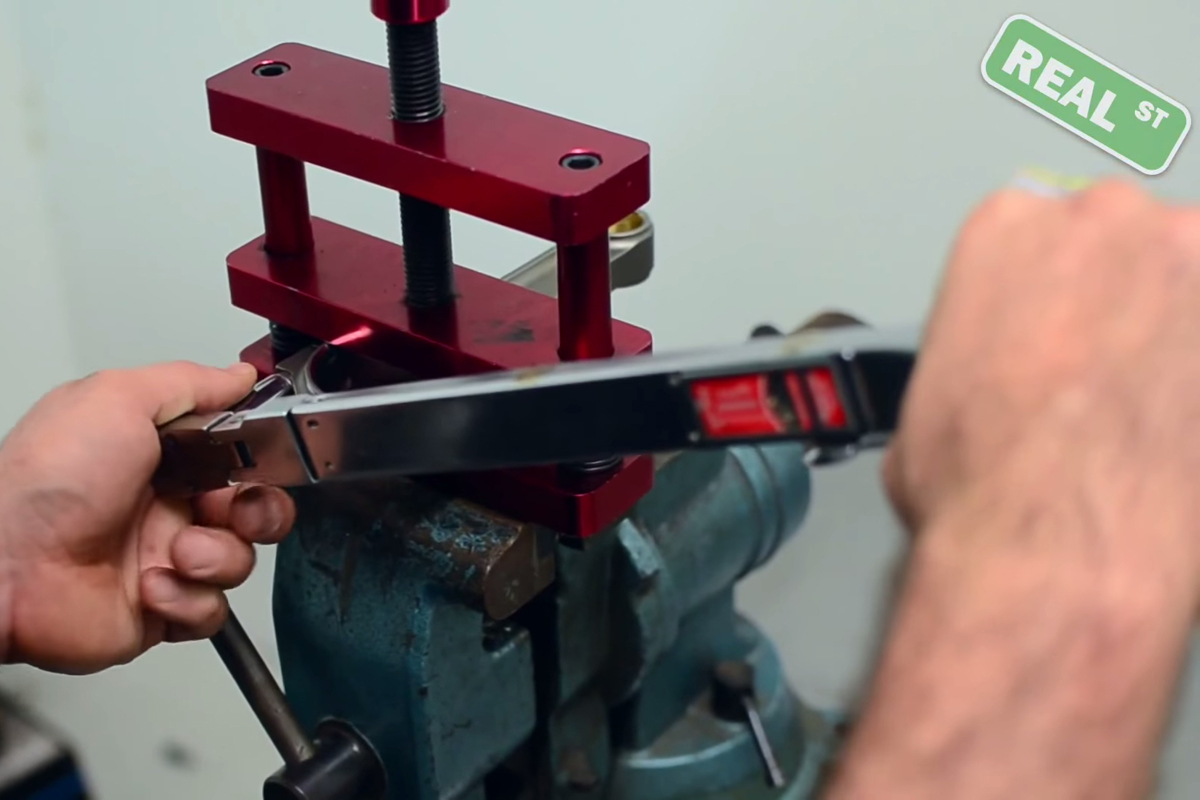
7. To apply the proper preload to the studs follow the manufacturer’s recommendations.
Torque the nuts in three even steps until you reach the recommended torque spec.
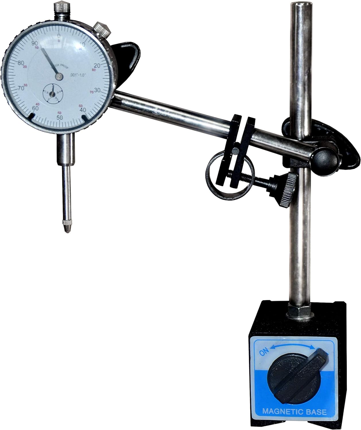
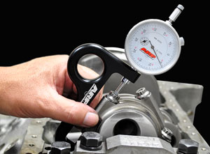
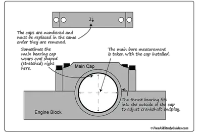
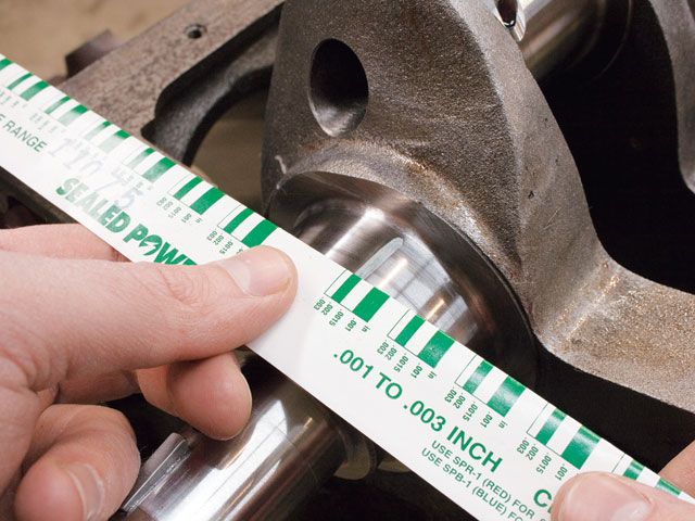
Note: clamping forces will change when installing new studs. Check the main bearing housing bores for proper size and out of round condition. In most cases align honing the mains with the new studs properly torqued will be necessary to ensure proper fit and clamping forces.
Editors note: If you found this article helpful, please click HERE to let them know and to order you copy of their 2013 catalog.
http://garage.grumpysperformance.com/index.php?threads/torque-specs-calculator-links-etc.1222/
http://garage.grumpysperformance.com/index.php?threads/splayed-main-caps.1014/
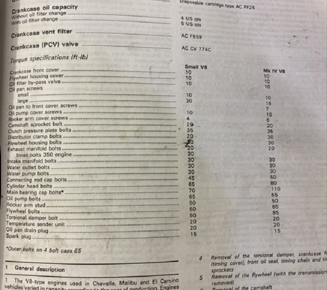
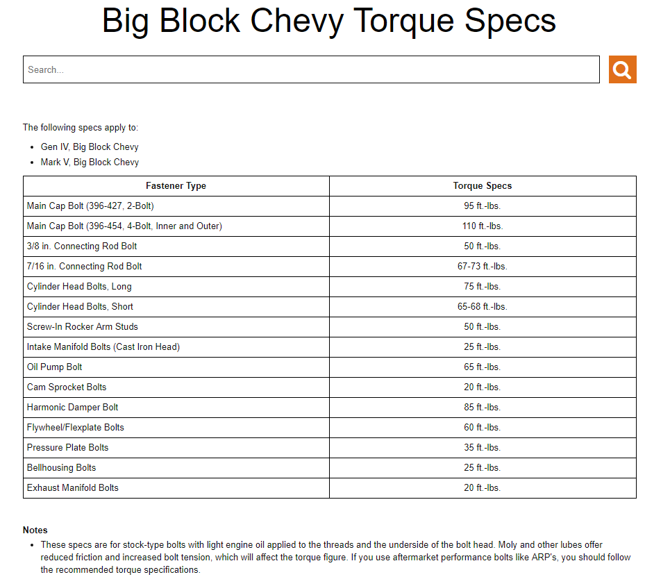
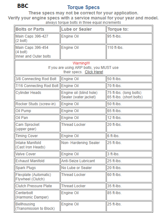
O.E.M. factory bolts use the 110 lb torque
ARP main cap bolts and STUDS CAN and frequently DO require a different torque
splayed aftermarket main caps generally use smaller diameter outer bolts that require less torque
 www.mahle-aftermarket.com