You are using an out of date browser. It may not display this or other websites correctly.
You should upgrade or use an alternative browser.
You should upgrade or use an alternative browser.
My Cam Research for the Experts Eye
- Thread starter TXChevy
- Start date
Got it, thanks. I went back and tweaked the routing again. I'll now be able to do all the flares/fittings off the car, then set the lines into place.
I've also seen that less expensive steel 37d JIC fittings will work for my less than 60 psi fuel system. I've made my list of what I need, just doing some homework on an industrial supply source.
Edit - so after some research into a source for fittings, I found a source for very reasonably priced plain steel JIC fittings, it was one of the places listed in one of the many links I've gone through. Hoseandfitting.com. I did the red/blue AN push-lok fittings last time and I prefer more of an updated utility functional look with hard lines as much as possible. At the very reasonable prices I can get some extras as well.
Last edited:
I agree with you. I've also found many good quality tools at swap meets and flea markets.Ridgid tools are it for plumbing and HVAC tools I couldn't tell you how many times in Home Depot I would see someone buying a cheaper tool to do some work and I talk them into spending 2 more dollars and buying the best
I'll follow up in a few days. As you've no doubt experienced there's times in a build project where there's lots of things "pending".
I've got parts and tools in shipping somewhere and in the meantime I'm working on fuel line routing plus small misc stuff that comes up.
I did visit my block at the shop today and it should be ready in a couple of days. They're also swapping my pistons onto the new rods.
I have decided on the straub 288/294 cam kit but won't order until block is finished just to be sure there's no glitches.
Since this looks to be the final camshaft, even if it's not won't matter. Below is a 17 pageI have decided on the straub 288/294 cam kit but won't order until block is finished just to be sure there's no glitches.
PDF report (1 page was blank, so I deleted) on your engine, if there is something that's
not correct, let me know and I will correct it before you order. Dynomation does more
than predict the HP/TQ curve.
You will also get to see some of the assumptions that I made, like the intake manifold. Not
that it will make any sense to you, but none the less it's there. I suppose you could download
the manual or I could post it if your interested.
But the headers dimensions will make sense. Things like primary tube diameter and length.
This is more of a Dynomation assumption, other than I selected open headers.
Attachments
Last edited:
I'd like to let you think that I put in several hours to create that report, but alas I cannot tell a lie !WOW and another WOW lol.
Blown away by your providing this.
It was just a few mouse clicks and mainly adding my name as the "Engine Tester" and your name
as the "Engine Designer" to give it that SPECIAL touch. LOL !
It's still very much appreciated Rick.
So here's some comments, I think most of this won't make any difference, only to verify some data. I'm listing them here as my thinking out loud when looking at the info, please correct me wherever needed! All in all, I'm happy with the simulated outputs and still taking into account there are some assumptions made. I think this engine will (1) be a driveable dependable combination and (2) have a moderate increase in p/t as well as where they occur in the rpm range. Both were primary goals.
P3 - Altitude is 213 ft, humidity is 60%,
Induction Type = divided plenum (Edelbrock RPM) Not the air gap version.
P5 - Rocker ratio is 1.7 (cam catalog shows 1.6 but I verified the numbers are with 1.7)
Valve overlap is 69.5, Primary .006 Timing EVO is 76.5, EVC 38.5, True .006 Timing EVO 76.5, EVC 38.5
P9 - I think peak flywheel (brake hp?) power peak @4600 is reasonable and useful by that rpm. Torque peaks @ 3600 which is what's moving the car. I don't exactly understand the delta @ 5000, with flywheel hp 399.9 and indicated hp 482.8 - this is telling me that the engine is losing about 83 "usable" hp? I assume from smaller valves/stock heads etc?
P10 - 6k piston speed @ 4000 ft/m was the target, so that looks good. The VE floats around 90-105% in the "daily" rpm range of 2400-4800 rpm which seems to make sense based on what I see for stock and mildly modified engines. I don't know about a realistic mechanical efficiency target for this type engine, I guess the fuel conversion efficiency is a bit low since this isn't an economy build?
P11 - I had spent considerable time setting up the ignition curve for the current engine and it was worth the time. In looking at the timing data shown on this page, are these target numbers for setting the ignition curve for this combination?
P17 - I was wondering what that small extra bump was on the exhaust velocity as the exhaust ramp was closing. Also, the center of the pressure overlaps looks to be just before TDC - my assumption is that even though the cam is installed at 0 degrees, that's the "static" installation where the overlap center is right at TDC? The mid point of these pressure overlaps is before TDC because of what's going on with exhaust and intake charges?
P18 - I know this one's for cylinder pressure but I couldn't correlate this one with the velocities chart.
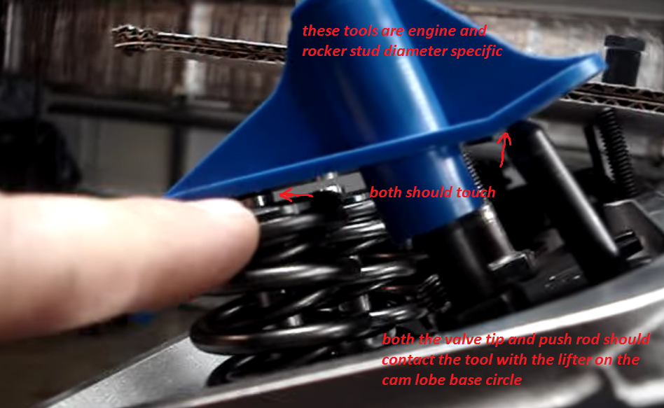
As mentioned I plan to get this Straub 288/294 cam with their recommended springs/retainers/etc and the Morel 5374 lifters (I've looked at a lot of info on them, including noise issues, it appears though that most are happy with them and that the noise issue posting were from a number of years ago.) I will closely check lifter bore dimensions though. I'll get their roller rockers which are Crane gold rockers. I'm not getting their pushrods as there will be a time period for me to take the heads in, install, check clearances, and measure for pushrods, so I think that I can simply order the correct length pushrods from another source when I'm ready for them.
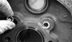
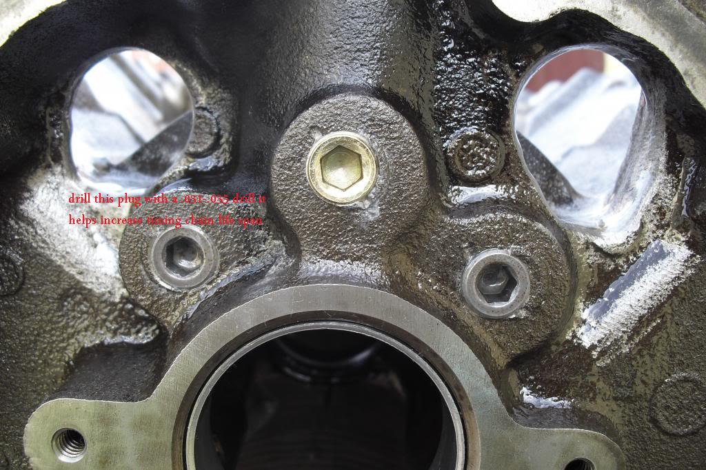
One question to verify drilling the block front oil galley plug with a .030 hole - is this for only the passenger side or for both sides? I see different info on this. I'm getting the drilled plug(s) from the machine shop so it's an easy install.
I want to thank you again for doing all this, it's extremely helpful. I think I'm ending up with components that will work for my goals rather than just reading cam descriptions and installing at 4 degrees advanced!
So here's some comments, I think most of this won't make any difference, only to verify some data. I'm listing them here as my thinking out loud when looking at the info, please correct me wherever needed! All in all, I'm happy with the simulated outputs and still taking into account there are some assumptions made. I think this engine will (1) be a driveable dependable combination and (2) have a moderate increase in p/t as well as where they occur in the rpm range. Both were primary goals.
P3 - Altitude is 213 ft, humidity is 60%,
Induction Type = divided plenum (Edelbrock RPM) Not the air gap version.
P5 - Rocker ratio is 1.7 (cam catalog shows 1.6 but I verified the numbers are with 1.7)
Valve overlap is 69.5, Primary .006 Timing EVO is 76.5, EVC 38.5, True .006 Timing EVO 76.5, EVC 38.5
P9 - I think peak flywheel (brake hp?) power peak @4600 is reasonable and useful by that rpm. Torque peaks @ 3600 which is what's moving the car. I don't exactly understand the delta @ 5000, with flywheel hp 399.9 and indicated hp 482.8 - this is telling me that the engine is losing about 83 "usable" hp? I assume from smaller valves/stock heads etc?
P10 - 6k piston speed @ 4000 ft/m was the target, so that looks good. The VE floats around 90-105% in the "daily" rpm range of 2400-4800 rpm which seems to make sense based on what I see for stock and mildly modified engines. I don't know about a realistic mechanical efficiency target for this type engine, I guess the fuel conversion efficiency is a bit low since this isn't an economy build?
P11 - I had spent considerable time setting up the ignition curve for the current engine and it was worth the time. In looking at the timing data shown on this page, are these target numbers for setting the ignition curve for this combination?
P17 - I was wondering what that small extra bump was on the exhaust velocity as the exhaust ramp was closing. Also, the center of the pressure overlaps looks to be just before TDC - my assumption is that even though the cam is installed at 0 degrees, that's the "static" installation where the overlap center is right at TDC? The mid point of these pressure overlaps is before TDC because of what's going on with exhaust and intake charges?
P18 - I know this one's for cylinder pressure but I couldn't correlate this one with the velocities chart.
As mentioned I plan to get this Straub 288/294 cam with their recommended springs/retainers/etc and the Morel 5374 lifters (I've looked at a lot of info on them, including noise issues, it appears though that most are happy with them and that the noise issue posting were from a number of years ago.) I will closely check lifter bore dimensions though. I'll get their roller rockers which are Crane gold rockers. I'm not getting their pushrods as there will be a time period for me to take the heads in, install, check clearances, and measure for pushrods, so I think that I can simply order the correct length pushrods from another source when I'm ready for them.
One question to verify drilling the block front oil galley plug with a .030 hole - is this for only the passenger side or for both sides? I see different info on this. I'm getting the drilled plug(s) from the machine shop so it's an easy install.
I want to thank you again for doing all this, it's extremely helpful. I think I'm ending up with components that will work for my goals rather than just reading cam descriptions and installing at 4 degrees advanced!
Last edited:
Thanks Grumpy, I'll install that.
More questions - I started looking at cam endplay/walk. I read where roller cams have a tendency to walk forward, so my understanding is there are 2 options for my Mk 4:
1 - use the 'regular' cam and install timing chain set that is set up for torrington bearing and use cam button with good quality cover or cover with built-in cam adjustment like the Cloyes 9-231. I realize short water pumps may need shallow bolts etc.
2 - buy the cam as a step-face, use a retaining plate and Gen 6 timing set.
Since I've not ordered anything yet, what would you advise? The Straub 288-290 is available in either configuration.
if your blocks set up to use the newer cam with the extended nose, use option #2

below you see the more modern block with the cam retainer plate and this uses a step nose cam, un-like the standard first gen non-roller cam blocks

youll really want to use a cam retainer lock plate, over the cam button and under the three cam bolts to hold the cam button into the timing gears, and lock the bolts from getting loose if you use a cam button on the older blocks.
like pictured below
notice the stepped cam nose to fit retainer plate,(yes pictures are SBC, but BBC is similar)
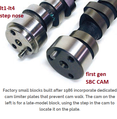
if the blocks the older style go with option #1

youll want to use a cam button and bolt retainer plate the picture above shows the cam button installed without one, thats wrong

yes as usual, much of the info you need is in links and sub=links
http://garage.grumpysperformance.com/index.php?threads/checking-piston-to-valve-clearances.399/
http://garage.grumpysperformance.com/index.php?threads/valve-train-clearances-and-problems.528/
http://garage.grumpysperformance.com/index.php?threads/rocker-push-rod-wear-issues.9815/
http://garage.grumpysperformance.co...ectly-and-get-it-to-last-cam-install-info.90/
http://garage.grumpysperformance.com/index.php?threads/check-cam-valve-lift.15893/#post-95551
http://garage.grumpysperformance.co...-pushrods-and-check-info-you-might-need.5931/
http://garage.grumpysperformance.com/index.php?threads/pushrod-length-tolerance.15189/#post-86920
http://garage.grumpysperformance.co...ng-combustion-chambers.2630/page-2#post-54342
http://garage.grumpysperformance.co...train-clearances-and-problems.528/#post-79273
http://garage.grumpysperformance.co...mble-and-swirl-quench-squish.4081/#post-12283
http://garage.grumpysperformance.com/index.php?threads/valve-to-piston-clearance.16349/#post-99047
below you see the more modern block with the cam retainer plate and this uses a step nose cam, un-like the standard first gen non-roller cam blocks
youll really want to use a cam retainer lock plate, over the cam button and under the three cam bolts to hold the cam button into the timing gears, and lock the bolts from getting loose if you use a cam button on the older blocks.
like pictured below
notice the stepped cam nose to fit retainer plate,(yes pictures are SBC, but BBC is similar)
if the blocks the older style go with option #1
youll want to use a cam button and bolt retainer plate the picture above shows the cam button installed without one, thats wrong
yes as usual, much of the info you need is in links and sub=links
http://garage.grumpysperformance.com/index.php?threads/checking-piston-to-valve-clearances.399/
http://garage.grumpysperformance.com/index.php?threads/valve-train-clearances-and-problems.528/
http://garage.grumpysperformance.com/index.php?threads/rocker-push-rod-wear-issues.9815/
http://garage.grumpysperformance.co...ectly-and-get-it-to-last-cam-install-info.90/
http://garage.grumpysperformance.com/index.php?threads/check-cam-valve-lift.15893/#post-95551
http://garage.grumpysperformance.co...-pushrods-and-check-info-you-might-need.5931/
http://garage.grumpysperformance.com/index.php?threads/pushrod-length-tolerance.15189/#post-86920
http://garage.grumpysperformance.co...ng-combustion-chambers.2630/page-2#post-54342
http://garage.grumpysperformance.co...train-clearances-and-problems.528/#post-79273
http://garage.grumpysperformance.co...mble-and-swirl-quench-squish.4081/#post-12283
http://garage.grumpysperformance.com/index.php?threads/valve-to-piston-clearance.16349/#post-99047
Last edited:
If you are saying that where you live is 213 ft and 60% humidity, then the dyno test are done to a standard and the HP/TQ is corrected to that standard. In this case the standard is J1349. Standards are used so you can compare dyno results whether they be run at sea level or in Denver.P3 - Altitude is 213 ft, humidity is 60%,
Induction Type = divided plenum (Edelbrock RPM) Not the air gap version.
I don’t have the option to input a specific model of intake manifold, I have to pick from Maximum-Torque, Standard-Flow, High-Flow, Max-Flow.
I'm not sure what you meant by repeating the same timing numbers. Mine are shown below.P5 - Rocker ratio is 1.7 (cam catalog shows 1.6 but I verified the numbers are with 1.7)
Valve overlap is 69.5, Primary .006 Timing EVO is 76.5, EVC 38.5, True .006 Timing EVO 76.5, EVC 38.5


I changed the rocker ratio to 1.7, but kept the lift at .578/.578. It did make more of a difference than I thought it would. I hope you can read the RPM and HP/TQ numbers, they are the same as every other graph before.

Indicated HP is what you would have if there were no losses in the engine, but we know that’s not true in the real world. Dynomation breaks out two different losses called “Frictional Power” and “Pumping Power”. If you take …..P9 - I think peak flywheel (brake hp?) power peak @4600 is reasonable and useful by that rpm. Torque peaks @ 3600 which is what's moving the car. I don't exactly understand the delta @ 5000, with flywheel hp 399.9 and indicated hp 482.8 - this is telling me that the engine is losing about 83 "usable" hp? I assume from smaller valves/stock heads etc?
Ind HP – Fric HP – Pmp HP = FlyWhl HP
482.8 – 49.9 – 33.0 = 399.9 HP
Does this help ???
I can't really answer your question about mech eff and fuel conv eff without some research.P10 - 6k piston speed @ 4000 ft/m was the target, so that looks good. The VE floats around 90-105% in the "daily" rpm range of 2400-4800 rpm which seems to make sense based on what I see for stock and mildly modified engines. I don't know about a realistic mechanical efficiency target for this type engine, I guess the fuel conversion efficiency is a bit low since this isn't an economy build?
I'm sure you already understand that mean piston speed is an average, but some people don't understand just HOW MUCH more above average velocities and accelerations can get. And just how much does that piston weigh when the crank yanks it back down after TDC.
I can elaborate more on piston speed. The 4,000 ft/min is just the average piston speed. Your engine with it's 4" stroke and rod length of 6.135", the piston will reach a max velocity of 6,611 ft/min at 6,000 RPM . Most people would guess that max velocity would occur at 90° ATDC, but in your case it happens at 73° ATDC. Assuming a piston weight of 550 grams, the piston will weigh 3,288.1 lbs at TDC.

I would say they are only rough numbers, there are just too many factors that go into the REAL timing numbers. Below is a link the 318 page Dynomation User Manual and on page 184-185 is the explanation for ignition timing and other options that are available. Let me know if you would like to investigate any of these options.P11 - I had spent considerable time setting up the ignition curve for the current engine and it was worth the time. In looking at the timing data shown on this page, are these target numbers for setting the ignition curve for this combination?
A major factor in ignition timing is the combustion chamber and again Dynomation must make some approximations by limiting the number of choices. Read page 182 of the manual. If you want me to select a different chamber I can do that.
Which bump are you talking about ?P17 - I was wondering what that small extra bump was on the exhaust velocity as the exhaust ramp was closing. Also, the center of the pressure overlaps looks to be just before TDC - my assumption is that even though the cam is installed at 0 degrees, that's the "static" installation where the overlap center is right at TDC? The mid point of these pressure overlaps is before TDC because of what's going on with exhaust and intake charges?

I would have to agree with you, it takes time for the gases to get moving again after stopping.
P18 - I know this one's for cylinder pressure but I couldn't correlate this one with the velocities chart.
I couldn't make sense of that graph with pressure on both axis.
Maybe this will make better sense.

.
Last edited:
Rick, thanks for taking a look at my questions, even the trivial ones. Helps me fill in some knowledge gaps.
On the overlap, the numbers I had for seat to seat valve timing were EVO 76.5 and EVC 38.5 but I'll check. Real-world I can't see this is any difference, only an observation of the numbers.
All in all this info to me looks to reinforce that for my purposes, the combo I have will work well. Maybe not taking every bit of p/t, but I'm ok with that. I want an engine that will work dependably.
I hope to pick up the block today, if that's the case then I'll put in my order for the cam (stepnose).
Thanks for the continued mentoring. I hope that someone else willing to ask questions will also gain from these posts.
Edit, just picked up my block from the machine shop looks great, measures out fine. Time for a good wash and into the bag.
On the overlap, the numbers I had for seat to seat valve timing were EVO 76.5 and EVC 38.5 but I'll check. Real-world I can't see this is any difference, only an observation of the numbers.
Yes, makes sense that the engine work costs something. Plus more loss from the th400 and Ford 9.Indicated HP is what you would have if there were no losses in the engine, but we know that’s not true in the real world. Dynomation breaks out two different losses called “Frictional Power” and “Pumping Power”. If you take …..
Ind HP – Fric HP – Pmp HP = FlyWhl HP
482.8 – 49.9 – 33.0 = 399.9 HP
Does this help ???
I keep letting that sink in - very enlightening. That 6611 ft/m is above what I think is termed as safe piston speed, so 6k rpm to me is really pushing it. Just something I need to keep in mind. Plus from looking at the simulations, by 5k rpm the engine is running out of steam anyway. That's fine because for my purposes the 2400-4800 rpm curve is where the engine will run almost all the time.I'm sure you already understand that mean piston speed is an average, but some people don't understand just HOW MUCH more above average velocities and accelerations can get. And just how much does that piston weigh when the crank yanks it back down after TDC.
I can elaborate more on piston speed. The 4,000 ft/min is just the average piston speed. Your engine with it's 4" stroke and rod length of 6.135", the piston will reach a max velocity of 6,611 ft/min at 6,000 RPM . Most people would guess that max velocity would occur at 90° ATDC, but in your case it happens at 73° ATDC. Assuming a piston weight of 550 grams, the piston will weigh 3,288.1 lbs at TDC.
No need for additional work on this - I understand what you're saying. I can do what I did before which was to run the engine through the rpm range and observe the timing changes (I had made some graphs on it to remember) and set the curve for optimum actual driving.would say they are only rough numbers, there are just too many factors that go into the REAL timing numbers. Below is a link the 318 page Dynomation User Manual and on page 184-185 is the explanation for ignition timing and other options that are available. Let me know if you would like to investigate any of these options.
A major factor in ignition timing is the combustion chamber and again Dynomation must make some approximations by limiting the number of choices. Read page 182 of the manual. If you want me to select a different chamber I can do that.
It was the bump right at the IVO valve event, just to the left of where you had pointed.Which bump are you talking about ?
Yes, I can understand that one!I couldn't make sense of that graph with pressure on both axis.
Maybe this will make better sense.
All in all this info to me looks to reinforce that for my purposes, the combo I have will work well. Maybe not taking every bit of p/t, but I'm ok with that. I want an engine that will work dependably.
I hope to pick up the block today, if that's the case then I'll put in my order for the cam (stepnose).
Thanks for the continued mentoring. I hope that someone else willing to ask questions will also gain from these posts.
Edit, just picked up my block from the machine shop
looks great, measures out fine. Time for a good wash and into the bag.
Last edited:
Not a problem, I'm enjoying the process also.Rick, thanks for taking a look at my questions, even the trivial ones. Helps me fill in some knowledge gaps.
No, it's mean piston speed of 4000 ft/min that is used as the rule for safe rpm. I was only pointing out that reality was quite different. Most anyone can calculate Mean Piston Speed, but the speed at any one point is much harder. I'm always amazed at the speeds/velocites inside an engine and wanted to point that out.I keep letting that sink in - very enlightening. That 6611 ft/m is above what I think is termed as safe piston speed, so 6k rpm to me is really pushing it.
OK, that bump if caused by the reflected wave from the collector reaching the exhaustIt was the bump right at the IVO valve event, just to the left of where you had pointed.
valve while it's still open and giving a little extra tug on the remaining exhaust gases,
while helping to pull in the fresh gases from the intake port/valve.
Read pages 284 thru 288 of the Dynomation manual.
Pay close attention to these two passages quoted below:
Page 284 ( This is the bump you are asking about )
When the compression wave produced at exhaust valve opening (EVO) reaches
the end of the header pipe (at the transition to the collector), a lower-strength expan-
sion wave is reflected back to the cylinder. The positive compression wave, now of
lower intensity, continues to move through the collector. When it reaches the atmo-
sphere boundary, a second expansion wave is generated that moves back through
the collector and into the primary header pipe. If the header system and cam timing
are properly coordinated, the first expansion wave will return to the cylinder at, or
slightly before, IVO.
Page 287
Peak exhaust velocity typically occurs twice during the exhaust cycle. The first
peak-flow event, at approximately 60 degrees after EVO, is produced by maximum
flow during blowdown. The second event occurs at maximum piston speed on the
exhaust stroke, about 73- to 82-degrees before TDC, and is the maximum flow during
exhaust pumping. In most well-designed engines, the first peak will be the greater
of the two (see Figure-16a); if the flow at the second peak is greater, it can indicate
excessive restriction in the exhaust system (see Figure-16b). When the exhaust
system is designed properly, the level of the first peak should fall between 0.45 to 0.5
Mach. If flow rates over 0.5 Mach are recorded, the exhaust system is too restrictive.
Just a heads up, I wasn't aware that there were two thrust plates available and I got theI hope to pick up the block today, if that's the case then I'll put in my order for the cam (stepnose).
wrong one. I don't know about the BBC, but if they show dimensions you might want to
verify it fits before ordering.
Also did you want a new report with the correct rocker ratios, it won't take more than
5 minutes ???
Ok, got it makes sense. It what I thought except this is explained very well.OK, that bump if caused by the reflected wave from the collector reaching the exhaust
valve while it's still open and giving a little extra tug on the remaining exhaust gases,
while helping to pull in the fresh gases from the intake port/valve.
Read pages 284 thru 288 of the Dynomation manual.
That dynomation manual has a ton of info, it's my nightly reading!
Yes please. I think that will close the loop on this set of components, thanks for doing this.Also did you want a new report with the correct rocker ratios, it won't take more than
5 minutes ???
I just ordered cam/lifters/spring stuff/retainer plate/rockers so I'm committed lol. Cam is the step-nose and as far as I know there's just one retainer plate for this block. It's going to be several weeks on the cam so I'll get the block prepped in the meantime plus work on the car. Right now I'm working to finish the fuel system.
I will get pushrods, timing set, etc as I go, using the advice here.
Incidentally the shop installed the front drilled galley plugs on both sides of the block - .030 hole in each. I've seen info on this and having both plugs drilled appears to be ok.
See the attachment below.Yes please. I think that will close the loop on this set of components, thanks for doing this.
What other oil system mods are you doing ?Incidentally the shop installed the front drilled galley plugs on both sides of the block - .030 hole in each. I've seen info on this and having both plugs drilled appears to be ok.
Keep in mind that the more places oil can flow from, the more volume you will
need to maintain the same good pressure. If you are only doing a couple of mods,
probably no problem with the stock pump. Start making 4-5 mods, then you
might want to consider a pump with more volume.
Attachments
The flare tool showed up today and I made some test flares with it. With a minimum of care, the flares turned out perfect. Worth every penny.Ridgid tools are it for plumbing and HVAC tools I couldn't tell you how many times in Home Depot I would see someone buying a cheaper tool to do some work and I talk them into spending 2 more dollars and buying the best
Rick, thank you for that last simulation. They all have been incredibly helpful to see the bigger picture.
I'm already using a Milodon hi volume pump with same brand 7 qt pan that works with the 57's steering. The only (minor) other things I've done was cleaning up casting flash in the valley drain slots and smoothing out the oil pump flow at the main cap. I'll measure the lifter bores to know what clearance is to the lifters and I'm considering adding the oiling slot in the distributor hole. Oil pressure was excellent before so with new bearings it should be the same or possibly a few lbs higher.
It's been my pleasure, you provided all the info needed in one place at the beginning and beenRick, thank you for that last simulation. They all have been incredibly helpful to see the bigger picture.
very appreciative of my efforts. Can't ask for anything more, I'm not doing it for money obviously,
just the need to help. Grumpy is the same way, if he had the money (I remember him saying) be
would open a school so he could teach.
Sometimes I have to search thru a persons thread looking for pieces of info and then search the
internet for their cam card to pull it all together. Hence the reason that I came up with that list I
posted at the beginning of your thread. If I can't get that filled out by the other person, then I
figure they are not that vested in the simulation so why should I. OK, I'm off my soap box ! LOL !
Well then, you should have all the oil system mods that you could want to do covered ! Well done !I'm already using a Milodon hi volume pump with same brand 7 qt pan that works with the 57's steering.
Don't hesitate to ask for anything else you need to be successful with this build !
block prep.
you really should read these links for a lot more USEFUL info, on block pre prep one of the least discussed & acknowledged, and yet more common reasons engines fail , is related to micro metallic crud left in the engine while its being assembled, especially engine's built on newly machined...
garage.grumpysperformance.com
oil system mods that help
heres a short list REMEMBER the object or goal in building and maintaining the lubrication system is too maintain a 100% dependable pressurized cooling flow of lubricant to the bearings, rockers ,valves etc. your most important tool, is your ability to think about how things are supposed to...
garage.grumpysperformance.com
whats a windage tray do?
"OK GRUMPYVETTE< I have dumb question? What is a windage tray and whats it for?" windage trays don,t provide a huge boost in horse power, the purpose is mostly in providing much improved oil control, thus they can, if properly designed provide a much more consistent oil supply, and enhanced...
garage.grumpysperformance.com
magnets
heres an old post "Any source for the magnets Grumpy? what do you use? " http://www.kjmagnetics.com/proddetail.a ... SH&cat=167 magnets are ceramic and glass hard, don,t try to drill or grind them, as they can shatter or http://www.magnet4sale.com/samarium-cobalt-discs/ proper magnets trap...
garage.grumpysperformance.com