My S10 ZR2 build

Ernest Shaw

Retired machinist
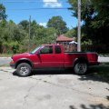
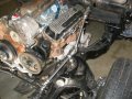
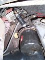
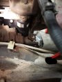
I'm starting out with a 1998 S10 ZR2 that I've had for a few years. The truck isn't anything special, just a project vehicle. I drove it a few years and age started catching up with it so I thought I'd start collecting some parts for a build. Good thing I did. One day I went out to start it and out of the blue the starter would grind whenever I tried to start it. Closer inspection showed that one of the starter mounting bolts was missing. I got one and went to replace it and found that the reason the bolt was missing was because the block was cracked were it goes in letting it work its way out. Ouch! Instead of trying to engineer a fix I decided that since it had so many miles on it, about 230K that I'd set it aside and collect parts for a v8 swap since the engine was coming out anyway. I have quite a stockpile of parts for it so I decided it's time to start using some of them. This is a pic of what I started with.
 

Attachments

  • My S10 ZR2.jpg
    My S10 ZR2.jpg
    45.9 KB · Views: 10
My first order or business is getting the 4.3 out of there. I thought the best way to accomplish this is to strip off the front sheet metal so that's what I did.
 

Attachments

  • stock engine bay.jpg
    stock engine bay.jpg
    142.8 KB · Views: 7
I took lots of pictures of what goes where for future reference to work in conjunction with my shop manuals. In addition I tagged where my electrical items went to help take the guess work out of it later, my memory isn't quite what it use to be! Next order of business is setting a engine in place and seeing what kind of mess I've gotten myself into.
 

Attachments

  • v8 installed.jpg
    v8 installed.jpg
    198.6 KB · Views: 9
There's a lot more to this than meets the eye is what I've come to realize but I like a challenge. The first thing I tried to do is free up as much available space as I possibly can to aid installation. The engine was installed with the same front dress as the 4.3 had and it bolted up in an identical manner. I did swap out the intake manifold and breather assembly just to get an idea how things would flow. I removed the a/c housing and installed a non a/c unit since I didn't use it but very rarely. Next item to go was the vacuum brake booster. In it's place I put a hydro boost unit. So far things are looking good for fit, that is until I got to the exhaust. The exhaust fits really well with the 1982 low performance Camaro exhaust manifolds but they fit the Vortec heads like poo. They look fine until you start doing more snooping. I also have a couple sets of LT1 exhaust manifolds so I decided to see what they would fit like. You'll see from the photos that they fit the Vortec heads a lot better but fitting them is a lot more work. First thing to address is the bolt pattern. For some reason these manifolds have smaller bolt holes on both sides of the center exhaust ports than the outer ones. This isn't a problem but kind of strange.
 

Attachments

  • stock pass LT1.jpg
    stock pass LT1.jpg
    187 KB · Views: 13
Both sets are identical so I know it wasn't just this one manifold. When a gasket is place on it you can see where the missing holes need to be.
 

Attachments

  • pass frt. missing hole.jpg
    pass frt. missing hole.jpg
    147 KB · Views: 7
Same thing is true on the other end but you can't do anything about it without using an adapter plate. I've heard that it can be run without the adapter plate so I will try that first. Both manifolds will be surfaced prior to final use so it may be ok.
 

Attachments

  • rear missing hole.jpg
    rear missing hole.jpg
    148.1 KB · Views: 3
Pics of the standard gasket like what's used with the Camaro manifolds on the head and the LT1 gasket on the vortec heads. You can see that the LT's a much better fit. Another reason to use the LT1 is the difference in exhaust diameter on this manifold is .25 inch larger. One other thing about the use of these is that the pipes that are connected to them have the pipe installed in a adapter that is much like those used on headers. By this I mean it's put into a triangular piece and welded on the back side. If clocking is an issue the pipe can be clocked however needed and re-welded or a complete new adapter made, easy peasy.
 

Attachments

  • std. gskt on vortec head.jpg
    std. gskt on vortec head.jpg
    109.3 KB · Views: 5
  • LT1 gskt on vortec head.jpg
    LT1 gskt on vortec head.jpg
    111.2 KB · Views: 5
Last edited:
With the manifolds installed there is plenty of clearance, however the drivers side manifold interferes with the intermediate steering shaft. After taking careful measurements the interference is 3/8 of an inch so the steering shaft needs moved to the drivers side another 3/4 inch so there is some additional clearance as well. The only alternatives to this would be to route out the manifold or move the engine to the passenger side the additional amount, neither of which I'm too crazy about. I'm thinking of trying something like this: I'm just not real certain how to go about it. The one in the pic has a lot more room than I do. My steering box is a lot closer to the firewall than this unit.
 

Attachments

  • offset steering.JPG
    offset steering.JPG
    204.8 KB · Views: 12
I love builds like this that stuff big engines in small compartments that the factory never intended.
This will test your engineering skills trying to make everything fit well. Keep at it. :thumbsup:
 
It looks to be a little earlier than what I'm dealing with, maybe around a 1995? Cleaned up the engine compartment too!
 
Got a little time today and did some measuring. Seems the steering is only off about 6 degrees from being straight so I should be able to use a heim bearing to support a dd shaft and jog around the offending manifold exit and still keep things relatively straight and still have some clearance. Another thing I discovered today is that my old stock leaky lines that ran from the oil adapter on a 4.3 block to the stock 4.3 remote oil filter under the radiator support will work just like advertised if I still want leaky lines. Still exploring my options on this. This is a real sore spot with owners of these trucks.
 
Got a little time today and did some measuring. Seems the steering is only off about 6 degrees from being straight so I should be able to use a heim bearing to support a dd shaft and jog around the offending manifold exit and still keep things relatively straight and still have some clearance. Another thing I discovered today is that my old stock leaky lines that ran from the oil adapter on a 4.3 block to the stock 4.3 remote oil filter under the radiator support will work just like advertised if I still want leaky lines. Still exploring my options on this. This is a real sore spot with owners of these trucks.
I remember putting those New Oil Cooler lines on my 1997 Blazer.
Changed every single oil seal on the Front and rear diffs.
Transmission and transfer case out.
Split the Front diff in 1/2 open.
Got it done in 2 nights at work old job.
 
1 month later the 4.3 V6 Blew up.
New ball joints Moog too.
Moog Idler arm.
$800 in New tires.

Said never again With a Chevy V6.
Junk.
 
Another thing I discovered today is that my old stock leaky lines that ran from the oil adapter on a 4.3 block to the stock 4.3 remote oil filter under the radiator support will work just like advertised if I still want leaky lines. Still exploring my options on this. This is a real sore spot with owners of these trucks.
I got my replacement lines from NAPA and they don't leak.
And I would be proud to own that blue S10.
 
I'm still fooling with the oiling system. I had a few choices on what cooler to use, pic included. The radiator I'm using is a new 4.3 type with the round cooler in the tank. I'm not a fan of this type so I removed it and installed a stock plate type. This will help heat up the oil some in the morning but I've also installed an external cooler to the radiator support. This hasn't been plumbed in yet, I'm still on the fence as to whether I'll need it. What I may do is leave it installed and if I have a need later it will already be in place and just need to have the lines run to it. If you're wondering about the tank on the radiator being removed I've done it before with no problems. I have the tools so...... On the last pic the stock line I was referring to earlier is #1 in the diagram. The other lines will require that I make them longer because I moved the radiator into the radiator support, effectively making the hookup longer. If you change one thing you have to make a concession somewhere else but that's the name of the game isn't it?
 

Attachments

  • oil cooler choices.jpg
    oil cooler choices.jpg
    166.6 KB · Views: 7
  • oil cooler installed.jpg
    oil cooler installed.jpg
    192.7 KB · Views: 7
  • 4.3 oil cooler diagram.jpg
    4.3 oil cooler diagram.jpg
    38 KB · Views: 8
Ideally, you want engine oil temps to stay in the 200F-220F range the vast majority of the time and trans fluid temps to stay in the 155F-165F range.
coolant temps in the 190F-210F range are rather common now with emission tuning, older engines seemed to run a bit better if you could keep coolant temp under 190F
 
I'm looking for a suggestion or two. Where are the best places to tap into for temp gauges when measuring the fluid temps for trans and engine oil? I was thinking of this location in the picture of a Camaro (second pic) as I've seen the port on other oil mounts like the one I'm using (first pic), but haven't really got a good idea on the trans though. If that spot for the oil would be good it would be ideal for my situation as I wouldn't have far at all to run the line to a guage inside the cab is why I ask.
 

Attachments

  • oil sender on camaro.jpg
    oil sender on camaro.jpg
    84.6 KB · Views: 8
  • filter clearance.jpg
    filter clearance.jpg
    99.6 KB · Views: 8
Last edited:
For the trans, there are two places to measure fluid temp. In the output line going to the cooler, this
is where you will see the highest temps. But measuring here will drive you crazy watching those temps
as they are 30-40°F higher than the pan and fluctuate much more. The pan will be more of a constant
temp and changes will occur more slowly.

You may have seen the graphic below, but TCI don't say where they are measuring, so I sent them an
email to find out. TCI said those numbers are temps for the pan.

http://www.tciauto.com/tc/trans-life-expectancy/

TCI_TransTemp.JPG
 
Last edited:
Back
Top