busterrm
solid fixture here in the forum
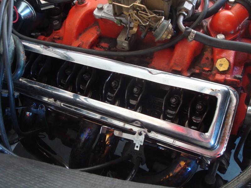
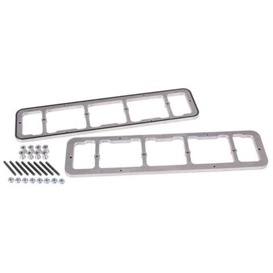
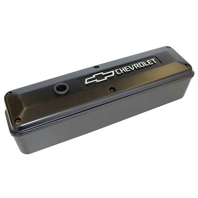
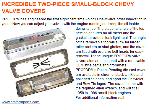
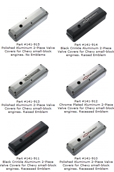
Yes, valve covers are Proform, pulleys and brackets are matched set, can't remember the brand, thet are from a eBay store I want say up in Minnesota. Valve covers I watched eBay for till I found them for 195 bux, pulleys and brackets are billet and I waited them out for while to let the price drop to 650 bux. Yes they are very functional, pulleys lined up perfect, no adjustment at all needed. The valve covers are intended to keep valve adjustment from getting messy, but indycars proved splash guard is needed to block the rockers from squirting you in the face!I really like the look! Impressed..
I'm going to steal some of the styling, and look into the parts you used for my build...
The rocker covers and the pulleys you used, are there functionality benefits to them as well as looking good?

Last edited: