Unforgiven Project

Thank you for the links Grumpy. I browsed through them quickly tonight. I will spend more time with them over the weekend. I think I need to get a dyno report first before I can calculate shift points though.
What I meant by redline was... I seen the mean piston speed at 6700 RPM's on the chart. I was thinking that the rev limiter should be set at 6700 or lower to limit piston speed from exceeding 4200

Am I thinking correctly on this?
I understand that the shift points will be set by the power ban curve and may be alot lower than 6700. Without looking back through my thread... I think Rick's power curve that he calcutated for my motor peaked
around 6300 before falling off.

I look forward to reading the links this weekend though.

I got more done on the motor tonight and some pics.. But it's getting late for me and I have to head off to work in the morning. I will post the the events that transpired in the morning.
 
What I meant by redline was... I seen the mean piston speed at 6700 RPM's on the chart. I was thinking that the rev limiter should be set at 6700 or lower to limit piston speed from exceeding 4200

Where on the chart do you see 4200 piston speed?
 
The mean piston speed is 4199 in the box on the right in the pic. Grumpy states that you do not want to go over 4200
to be safe.
 
In this chart or one by Grumpy?
index.php
 
I did as Rick said and used my degree wheel to find TDC . Then for fun I used the information in the Excel Spreadsheet from yesterdays post
to verify the info. I spun the crank to 15 degrees and I got an indicator reading of .085, exactly what the spreadsheet says.

In the first pic below, after finding true TDC I reset the pointer a adjusted the indicator to zero. I found Rick was correct... After Using Rick's process checking for TDC...I found that I was originaly off by 1 degree. It don't sound like much, but in tuning.. it could mean the difference between smiling and frowning! ;)

IMG_0747.JPG

The next pic is what the reading looked like when I turned the crank to 15 degrees. As you can see... the indicator reads .085 ( moving counter clockwise on the dial).


IMG_0746.JPG


I also got a few pics of that front oil seal and what the differences where.

IMG_0748.JPG
Yes I dented the seal when I removed it from the cover. But you can see the height difference between the two.
IMG_0751.JPG IMG_0751.JPG
The pic above is the new Moroso seal ... it measures .378 thick.

Note that the OLD seal below measures just over 1/2" thick.

IMG_0755.JPG

That difference of .125 was enough to extend the seal through the back of the timing cover and contact the chain...creating metal shavings!
The pic below shows where the chain was hitting the edge of the seal.
IMG_0750.JPG

The next step was to install the cover, balancer, and pointer.

IMG_0757.JPG IMG_0756.JPG

The oil pump drive shaft came in so I got it and the pump installed. Torqued it to 65lbs. I prefit the pan to recheck that it clears because of all the repairs that were done to it, I then painted it and hung it above the wood stove to dry overnight. The fire at this point was a dying bed of coals,
so it was perfect for drying paint.
 
Yes T ... This chart shows my piston mass with the green and yellow arrow on the left and the MPS above the yellow arrow on the right.IMG_0744.JPG
 
this is a great example of (engine building" vs parts assembly)
yodam.jpg

yodaq.jpg

Id bet 80% or more of the people assembling parts have never checked most component clearances ,
except in most cases for ring end gap and bearing to crank journal, as thats almost mandatory.
things like,
piston to the cylinder head (quench)
piston to valve,
rocker slot to rocker stud,
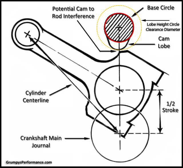
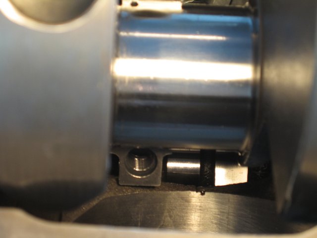
connecting rod to cam lobe,
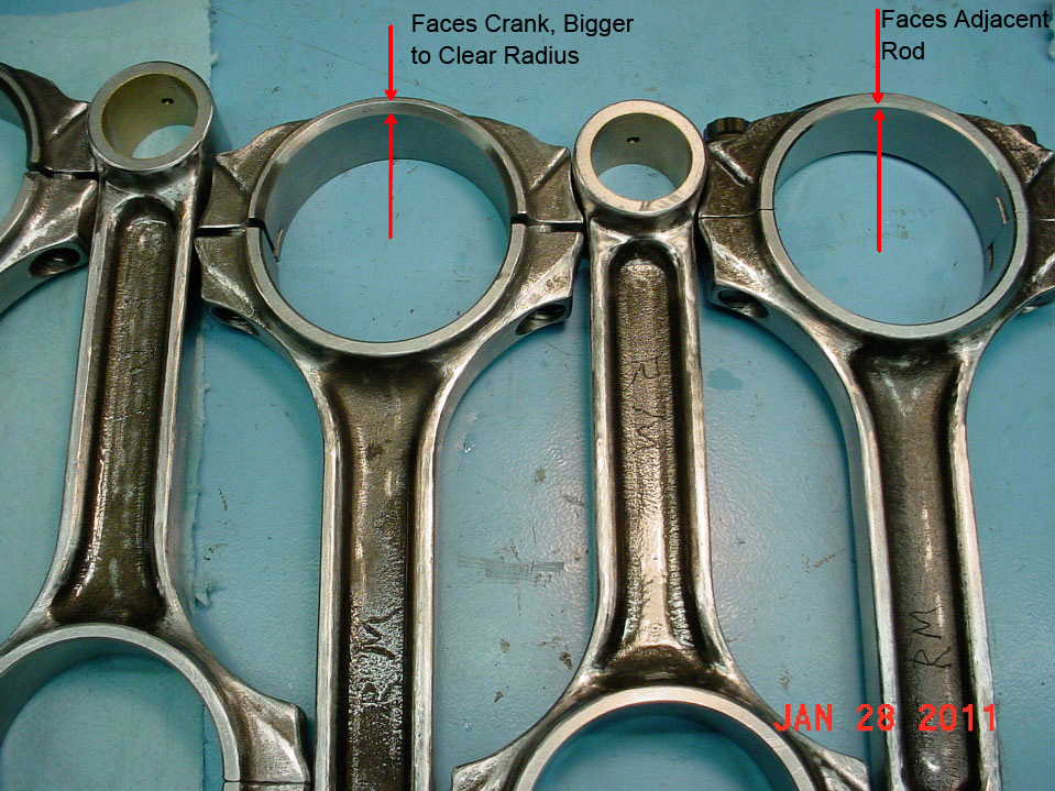
connecting rod to block skirt,
piston skirt to crank counterweight,
cam button to the timing cover,
spring bind height,
rod side clearance,
thrust bearing clearance,
ring end gap and piston slot back clearance on rings.
piston to bore clearance.
pushrod to the cylinder head, or guide plate,
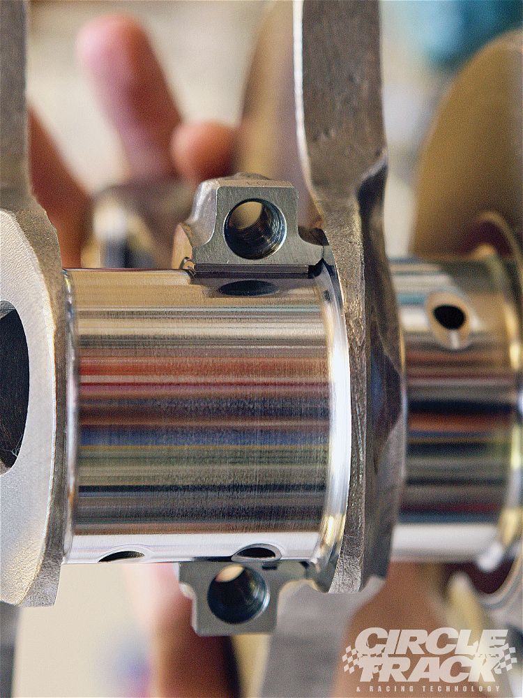
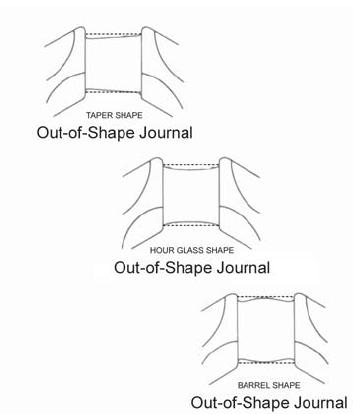
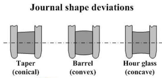
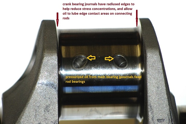
crank journal taper and concentricity and surface smoothness
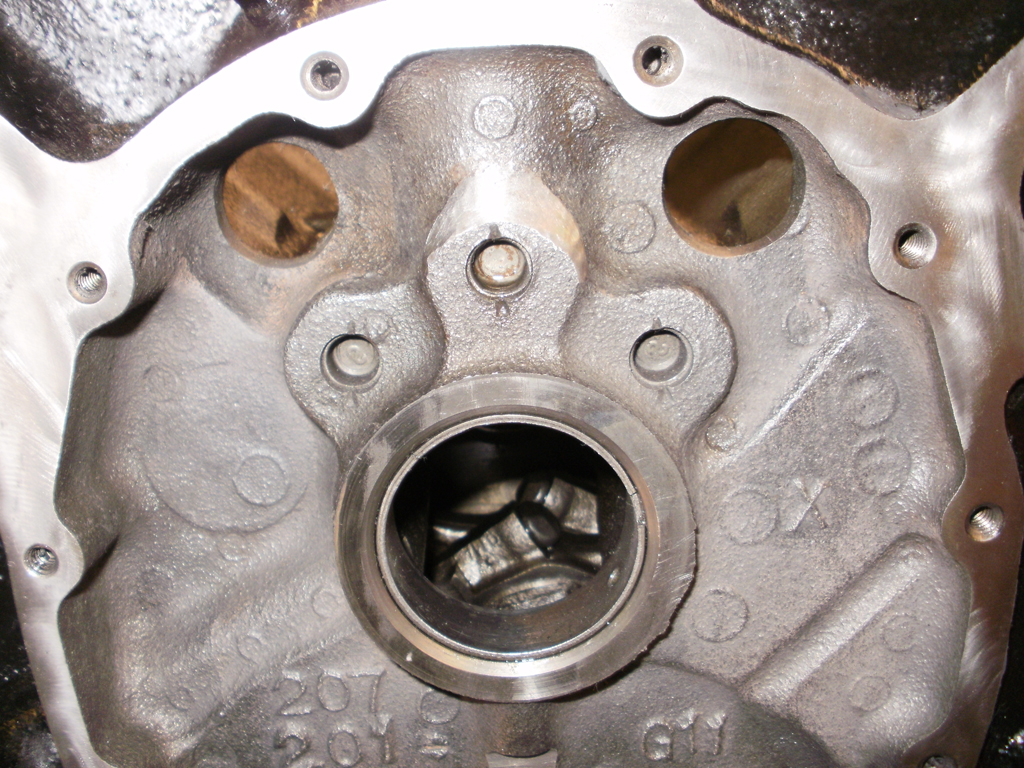
cylinder head surface and not being warped
cleaning out all the threaded holes with a tap.
sonic testing bore walls
having the block , crank and heads checked for micro-cracks
verifying the oil pump drive shaft has about .050 clearance with the distributor fully seated,
replace and shim distributor gear with new cam installation
verify oil pump relief spring function, test to ensure it opens at no higher than 70 psi
checking for crank straitness.
verify crank journal to counter weight junction has consistent radias
verify head gasket opening is at least .030 larger than bore diameter all the way around bore circumference
verifying main cap concentricity and shoulder depth.
verify pushrod length and valve train geometry.
timing chain slack, and/or lack of clearance to the timing cover.
verify theres no crud inside push rods or block oil passages.

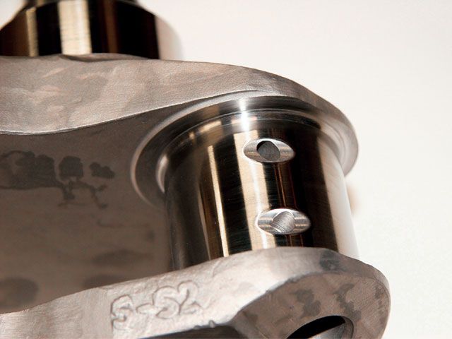
verify the block oil passages and bearing oil holes align properly (correct and bevel as required)
bearingoffset2.jpg

p117190_image_large.jpg

MEASURE CAREFULLY

bearingjournalz.jpg

journaltapers.jpg


chamferedhole.jpg


1310.jpg

crnk1a.jpg

BaseCircleDiaaaa.jpg

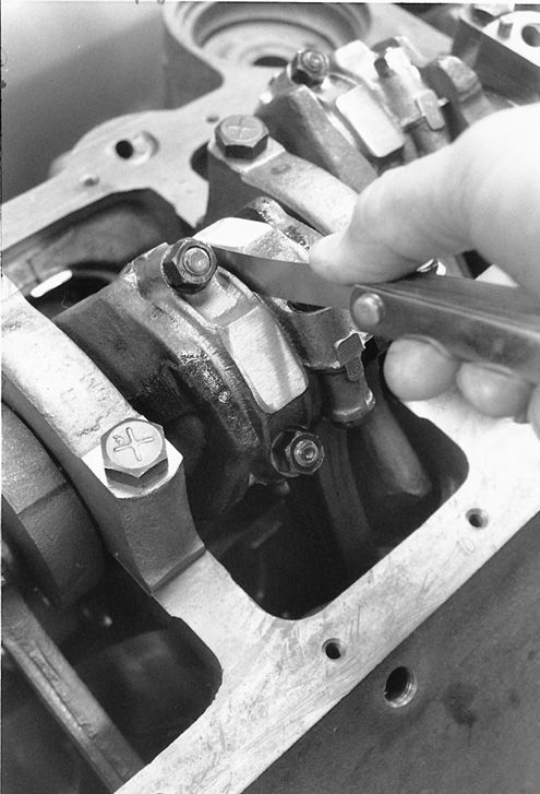
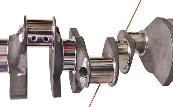
notice how the rod bolts come close to the cam bearings as the pistons reach top dead canter in the bores
block-clearance.jpg

rodcaptoblockclearance.JPG


crnk6.jpg


reading links and sub-links will take days ,
but it's sure to save you hundreds of dollars ,
and weeks of wasted effort.


http://garage.grumpysperformance.com/index.php?threads/bearing-clearances.2726/

http://garage.grumpysperformance.co...tion-of-crank-durring-short-blk-assembly.852/

http://garage.grumpysperformance.com/index.php?threads/another-rings-end-gap-question.14994/

http://garage.grumpysperformance.com/index.php?threads/oil-system-mods-that-help.2187/

http://garage.grumpysperformance.co...alves-and-polishing-combustion-chambers.2630/

http://garage.grumpysperformance.com/index.php?threads/valve-train-clearances-and-problems.528/

http://garage.grumpysperformance.com/index.php?threads/checking-piston-to-valve-clearances.399/

http://garage.grumpysperformance.com/index.php?threads/cam-bearing-install-tools-install-info.1479/

http://garage.grumpysperformance.com/index.php?threads/rocker-push-rod-wear-issues.9815/

http://garage.grumpysperformance.co...e-springs-and-setting-up-the-valve-train.181/

http://garage.grumpysperformance.com/index.php?threads/cylinder-head-resurfacing.15767/

http://garage.grumpysperformance.co...ng-and-basic-piston-ring-info-youll-need.509/

http://garage.grumpysperformance.com/index.php?threads/engine-assembly-tips.4294/
 
Last edited:
Rick.. is the rod weight included in the piston mass for that program? my piston and pin weigh 642 grams and my rod weighs 565 grams. Do I add these together or are they calling for just the piston mass of 642

It would depend on where you wanted to measure the stress. But you could only add the little end
of the rod, the rest of the rod is not feeling the same forces since it's going in a circle. Where the piston
is going in a straight line. This would tell you the stress in the middle of the rod beam. I'm not totally
sure that this is completely valid, as there might be more to the physics going on here than I'm aware of.

Normally what you are looking at is how much the piston, wrist pin and rings are stressing the rod where
it pulls on it thru the wrist pin. Therefore the same forces are pulling on the rod bolts, distorting the big
end of the rod and crankshaft.

so are you saying that this may be a redline for my motor according to the chart?
If 4200 fpm mean piston speed is the number you want to stay under, then yes you have ONE more rpm before the motor explodes.... just kidding about that last part !!! ;)

You should read the complete post, I talk about the difference in Mean Piston Speed and the absolute
Velocity at any point in the crankshaft rotation. Mean Piston Speed is just a rule-of-thumb, it's not the
holly grail when it comes to talking about the stresses. Also it's not the velocity but the acceleration
that's most important. Going 70 mph down the highway is easy on the human body, but when you hit
that semi truck going the other direction your deceleration is what's going to hurt.

Now if I understand correctly , at 15 degrees.. I should be .085 thousands into the hole..given the fact that I am zero decked.

Exactly !
 
Thanks John... I'm tying my best to check even the simplest of things, cause even though I thought I was careful the first time, Evidence shows I missed a few things. The links Grumpy supplies are VERY helpful if people would just stop and read. I can't wait to learn how to set my shift points
by using calculations instead of the seat of my pants. The Excel sheets that Rick supplied was so cool! I think I have a better handle on the scientific reasons a particular part will or won't work in a motor now. The MPS was something I thought was very interesting. I never actually knew how to calculate a safe RPM limit. I'm still not 100% positive yet , but I think I'm on the correct path for learning.
 
Did you check the end play in the oil pump drive shaft ?

Not yet Rick. My plan was to leave the pan off until I put the heads and intake on the block. Which will be tonight. I was then going to install the dizzy and lock it down
temporarily, then turn the engine stand mount so the lower half of the motor is facing up. That way I can physically set an indicator on the shaft
and move it up and down by hand to get an exact number.
What do you think.
 
What do you think.
Sounds like a plan, just wanted to make sure you were planning on checking the oil pump
driveshaft end play.

Rick... you still there? Where did you go?
I'm doing a complete re-install of all software on my garage computer, which includes upgrading
from Windows 7 to Windows 10, all my data, programs, bookmarks, etc, etc ..... So sometimes I
have to go off line to reboot or restore files and ......

We are at what's called "End of Life" for Windows 7, Microsoft will no longer be supporting
Windows 7 (no updates) in January 2020.
.
 
Beer always makes the job go smoother !!! ;)

Be prepared for some pain, there is always the passwords from websites, banks, etc. Making
sure data files are saved. Learning to use a new Operating System.
 
oh ok ... yea I already upgraded to 10 awhile ago. We keep an address book with all our passwords to everything for those P.I.A. situations you are talking about .

Well I'm off to the barn now. have a good day.
 
And people wonder why there are not as many local drag strips and racers like there used to be, racing has gone so scientific that us dumb bastards just can't keep up, literally.

$12000.00 cheap build engine plus car/truck at $25000.00 plus computer stuff at $15000.00 plus salaries for crew and trailer to haul it with at$100000.00 and my brain and pocket book hurt!!

Sports equal money pits that all cannot afford.

I finally see the piston speed and have never understood why that was so important when max RPM was set at a reasonable figure unless you are using the wrong/cheap pistons that will come apart above max RPM.
I stopped all racing in the mid 1980s when it got too technical for me.
 
Got alot done today.
First thing was to check the pick up height to clear the pan. the measured 7"deep so I set the pickup at 6.750 off the rail. with the gasket installed i should have about 3/8 to 7/16" clearance to the floor.

IMG_0759.JPG

I thought the deck looked dirty so I spent some time cleaning it.
IMG_0762.JPG

after the cleaning I re-installed the studs.

IMG_0764.JPG

then came the new head gaskets.

IMG_0767.JPG

They look even better on the deck!

IMG_0770.JPG
The gasket fit really well with no cylinder interference as shown below. I ordered 4.100 bore gaskets ... my cylinders are 4.040

IMG_0769.JPG

With the motor starting to look good.. I thought I would spend some time cleaning the heads too. the first pic below is what I started with and the next pic is a comparison of before and after.

IMG_0771.JPG

IMG_0772.JPG

After I got the heads cleaner , I installed and torqued them to 80lbs (per ARP). I then installed the rockers and got them adjusted. Once I got zero lash, I gave them a half turn then locked them down.
A 7/16-20 thread will move the pushrod .050 per revolution. I figued that since we want a preload of minimum of .020 and a maximum of .060.... A half turn would set .025 ....I am betting that this number will grow when the motor gets up to temperature and the preload will be around .030-.035

IMG_0773.JPG

The polylocks all look good and have no signs of binding.

IMG_0783.JPG
 
Back
Top