Unforgiven Project

TW, does Steve Morris hold you responsible if the motor damages the dyno? I was told by
the shop here in OKC that if the motor came apart on their dyno, I was responsible for any
damages. I hate to bring this up, but it's better to know the facts.

That's a darn good question Rick!! I will have to ask him.
 
I went thru and checked all the rods. I used Rick's advice and torqued the bolts several times each before a final torque reading.
The big end of the rods stayed in round within .0002 tenths. That two tenths reading was only in one direction on all rods. It was a 45* angle.
I marked all the bolts heads with the cylinder # and an "I" or an "O" for inner and outer. Glad I checked each individual bolt before and after install because the depth of the dimples on the bolts seem to vary quite abit as you will see in my findings below. Bolt stretch averages between .004-.0045 so I'm in spec!

IMG_0723.JPG
 
.
Jim, you left me hanging wanting to know just how much the stretch varied by cylinder !!!

Sorry, I could not resist making up a pretty Excel table so I could see all the stretch
values by cylinder. As always, you will want to verify my numbers.

I assumed you would torque each bolt until you got the stretch you wanted of .0045 inches.
Instead you torqued everything to 70 ft/lbs and then looked at the stretch acquired. Looks
like you did a fine job, just a different approach on my part.

RodBoltStretchChart01.jpg
.
 
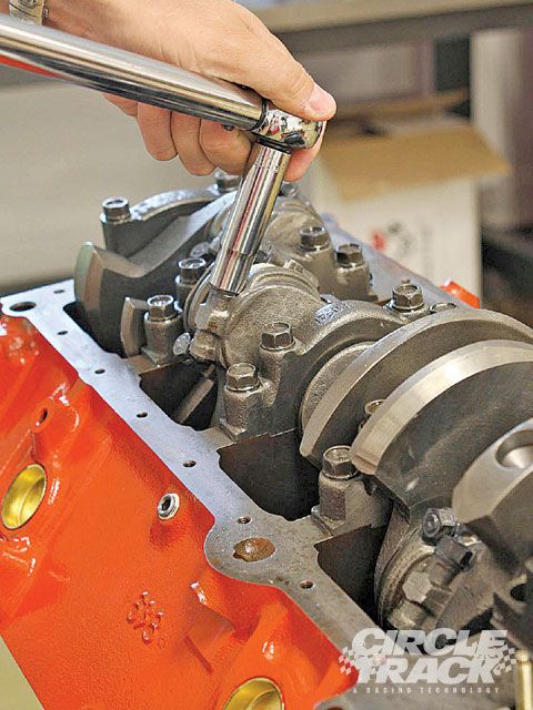
most engines using nearly stock rod designs with arp rod bolts don,t seem to suffer a bit using a torque wrench, if you use the correct tech and lubes
arp-ultra-torque-fastener-assembly-lubricant
if as previously mentioned, the rods bolts are tightened and loosened three successive times and torqued to the recommended
torque suggested
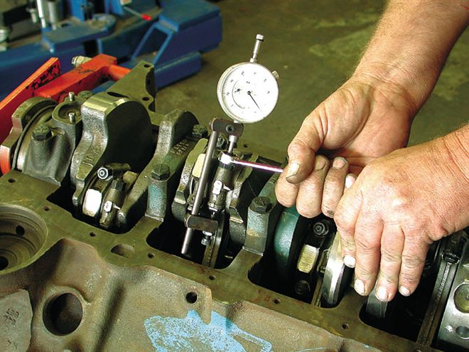
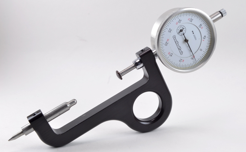
yes I generally use a rod bolt stretch gauge on anything built for serious performance,
but as the chart above illustrates the difference in the results is not huge in most cases.
btw most ARP rod bolts use 12 point nuts, so a 12 point deep socket
ctrp_0901_19_z+limited_late_model+race_engine_build.jpg


I got this email from Chris B. ar ARP concerning this post. It is very interesting so I am reposting it here with his permission for all to read.


Hi Dave,

Chris Brown from ARP here. I was forwarded your e-mail discussion by a
friend who looks at the Team Chevelle website every now and then.
What you have been experiencing is the frustration of the age old battle
Of torque and friction versus load. The reason for all the different
results from different lubes and torque values, is due to the amount of
friction present between the surfaces that are scuffing against one another.
The most important factor to monitor is the stretch, because the bolts work
like a spring. To generate load, you must extend, or stretch the spring.
The amount you stretch the bolt is determined by the length, diameter
and the strength, but let's not get into that now. We at ARP calculate
the stretch for each bolt design, based on 75% of its yield strength,
the yield being the point at which the bolt has reached it's peak load
and then "feels funny".Torque is simply a twisting force, index number,
it does not equal load. The amount the rod bolt (in this case) stretches,
is determined by how much friction you have to overcome. With engine oil,
there is more friction generated than with ARP Moly Lube. This because the
friction coefficient or index if you like, for oil, is more than that of
the moly lube. In other words it is slicker. Therefore, it will take less
torque typically with moly lube, than with oil, to achieve the same amount
of stretch in the bolt. As RJ in the discussion group says, "It seems like
there is extra drag on the nut." It is very hard to predict how much
friction there will be, between the surfaces, even when you have control
over the lubricant, because of the surface finish on the spot face of the
cap and the nut bearing surface.Therefore, it is hard to predict how much
the bolt will stretch, based on the torque value being applied. When using
the stretch gauge, none of these variables come into play Because you are
not relying on a certain friction value to give you the result you need.
You simply zero the stretch gauge on the particular bolt you are going
to install and tighten the nut until you reach the correct amount of stretch,
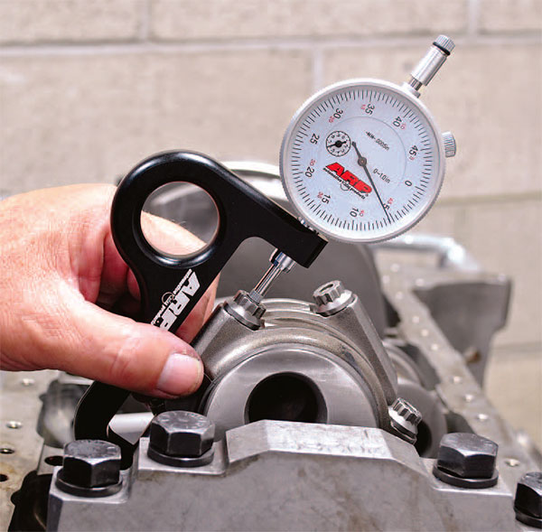
and therefore clamp load or preload and stop. You can, on a 3/8rod bolt,
use a long series box end wrench, put it on the nut, install the stretch
gauge over the top and watch the stretch gauge as you tighten the nut.
Several of the tool companies out there have extra long box end wrenches
for certain jobs and with more leverage, it is certainly easier.

Best regards,
rodboltyg.jpg

or box wrench is useful
https://www.xtremediesel.com/arp-ul...MIiN_xkvT05QIVCY6zCh2Z2Af3EAQYAiABEgJnNfD_BwE


100_9910_ARP_web_updated_600x600.jpg

116_0609_rod01_z.jpg


https://www.enginelabs.com/engine-t...easuring-rod-bolt-stretch-vs-torque-with-arp/

https://www.hotrod.com/articles/using-rod-bolt-stretch-tool/

http://garage.grumpysperformance.co...ng-rod-bolt-stretch-preload.11050/#post-85102

http://www.performanceenginetech.com/connecting-rod-bolts-stretch-vs-torque/


stretch-gage.jpg

Connecting Rod Bolts – Stretch vs. Torque
Today I’d like to discuss the proper method for performance connecting rod bolt installation. There are a few ways to tighten connecting rod bolts, including the basic torque method, the stretch method, and the torque to yield method. Without a doubt, bolt stretch is the only truly accurate way to establish proper bolt preload. To better understand why, we need to look at how a bolt works.

Understanding Stretch
A bolt functions similar to a spring, in that it needs to be stretched beyond it’s static length in order to apply a clamping force. In the case of a connecting rod bolt, the clamping force must exceed the tensile load imparted by the attached components during high rpm operation. This is accomplished through a combination of bolt material selection and stretch dimension.


A common method for determining ideal stretch, is by incrementally increasing the amount of stretch until the bolt becomes permanently elongated. This dimension is termed yield, and a typical target stretch range is then determined to be 75-80 % of yield, with the min/max provided to the end user at +/- 5 % of this target. As an example:

  • Yield = .007″ stretch
  • Target stretch is 75-80 % of yield = .0052″ – .0056″
  • +/- 5 % of target = Min/Max of .0049″ – .0059″ (recommended stretch range)
Yield varies, and is affected by a variety of factors, such as material, bolt length, under-head register length, and shank diameter.

Proper Use of Torque
As explained above, what we really want to do is install the rod bolt at a near optimal percentage of yield in order to apply as much clamping force as possible without putting the integrity of the bolt at risk. Using a torque wrench to tighten the rod bolts in your high performance engine is a risky proposition, unless you are willing to invest some effort into quantifying the readings.

Torque in regards to bolt tightening is just the amount of force required to overcome incremental increases in friction. Torque readings (friction) are affected by thread quality, composition of lubricant, and surface finish of the bolt spot-face machined on the cap of the rod. Beyond the friction variables, not all torque wrenches – or users for that matter, are created equal.

I have used nearly every type of torque wrench available, and have a very high quality calibration unit at my disposal. The only torque wrenches that are consistently correct throughout the scale of readings, are high quality dial type. The ever-popular “clicker” type wrenches rarely apply the torque that the user has dialed in, and the higher the torque, the more it’s off. With that being said, they will torque consistently, just not the proper amount of torque.

Torque vs. Stretch
Now that we understand that the stretch value is what needs to be achieved, it’s necessary to verify what amount of torque on the wrench being used is going to stretch the bolt within spec. All rod manufacturers provide an information sheet that will list the recommended torque spec and bolt stretch range. Here’s the process I use to match my torque wrench reading the proper stretch value:

  • Install the cap on the rod with the manufacturers recommended lube on the bolts.
  • Carefully draw the cap into the rod using a nut-driver alternating from side to side in order to keep everything square until the cap & bolts are properly seated.
  • Loosen one bolt just enough to be sure there is no load on it.
  • Install the bolt stretch gauge on the loose bolt.
  • Set the dial to “0” – remove and re-install gauge to verify it still reads “0”
  • Remove the gauge.
  • Finger tighten the loose, just measured bolt.
  • Torque the opposing bolt to 25 ft. lbs. – this assures it has a small amount of preload on it.
  • Torque the measured bolt to the manufacturer’s recommended value.
  • Install the stretch gauge, and see what the bolt stretched to.
  • If the bolt isn’t within specs, loosen and adjust torque up or down until you reach the desired stretch.
  • If the bolt is stretched within the specified range, loosen the opposing bolt and repeat the measure/torque/verify procedure.
  • Repeat these steps to 4 bolts to assure that the same torque reading provides the same amount of stretch.
At this point you should be able to use the torque wrench reading determined in the outlined process to torque the rest of the bolts, or continue to stretch each bolt individually. I should also be clear that you must zero the dial on the stretch gauge for each bolt. The center dimples used for the gauge are not a critical dimension, and will vary from bolt to bolt.

That’s all for today. I hope I’ve cleared up any of the mystery surrounding proper rod bolt installation for you. As always, I look forward to your feedback, questions, or comments. You can comment directly to this or any other article on the site or send me an e-mail. Please invite your friends to join us, and thanks for visiting …..
 
If you read thru Grumpy's post above then watching stretch as you torque the rod bolt nut is the better way to go. Quoted below for your convenience. Don't know why this would not work on a 7/16 inch rod bolt also. Maybe you have to make your own box end wrench.

You can, on a 3/8rod bolt,
use a long series box end wrench, put it on the nut, install the stretch
gauge over the top and watch the stretch gauge as you tighten the nut.
Several of the tool companies out there have extra long box end wrenches
for certain jobs and with more leverage, it is certainly easier.

Take note of the BOLDED text quoted below.

Torque vs. Stretch
Now that we understand that the stretch value is what needs to be achieved, it’s necessary to verify what amount of torque on the wrench being used is going to stretch the bolt within spec. All rod manufacturers provide an information sheet that will list the recommended torque spec and bolt stretch range. Here’s the process I use to match my torque wrench reading to the proper stretch value:

  • Install the cap on the rod with the manufacturers recommended lube on the bolts.
  • Carefully draw the cap into the rod using a nut-driver alternating from side to side in order to keep everything square until the cap & bolts are properly seated.
  • Loosen one bolt just enough to be sure there is no load on it.
  • Install the bolt stretch gauge on the loose bolt.
  • Set the dial to “0” – remove and re-install gauge to verify it still reads “0”
  • Remove the gauge.
  • Finger tighten the loose, just measured bolt.
  • Torque the opposing bolt to 25 ft. lbs. – this assures it has a small amount of preload on it.
  • Torque the measured bolt to the manufacturer’s recommended value.
  • Install the stretch gauge, and see what the bolt stretched to.
  • If the bolt isn’t within specs, loosen and adjust torque up or down until you reach the desired stretch.
  • If the bolt is stretched within the specified range, loosen the opposing bolt and repeat the measure/torque/verify procedure.
  • Repeat these steps to 4 bolts to assure that the same torque reading provides the same amount of stretch.
At this point you should be able to use the torque wrench reading determined in the outlined process to torque the rest of the bolts, or continue to stretch each bolt individually.

I should also be clear that you must zero the dial on the stretch gauge for each bolt. The center dimples used for the gauge are not a critical dimension, and will vary from bolt to bolt.

This is what you were referring to your statement above .... good catch Unforgiven !!!


The ever-popular “clicker” type wrenches rarely apply the torque that the user has dialed in, and the higher the torque, the more it’s off. With that being said, they will torque consistently, just not the proper amount of torque.

The above statement is important for using a Clicker type torque wrench.
.
 
The last heads I install at 175 lbs per ft I pulled the ligaments and tendons in my arm and you could hear them ripping away.

I DON'T DO ANY ENGINE WORK ANY MORE!!!:(:(:eek::eek: I DON'T LIKE PAIN!!!
 
It was a 460 Ford. Forget what head bolts used but that was the specs for them. Bored 090 thousandths and ran a tunnel ram with 2 1100 Deamons.
 
Thank you men.
All very good information.
I used the torque values Scat gave me (70LBS) to verify that I was not stretching past .005 when checked with the stretch gauge. This was done
with the rods in a vise that I had installed aluminum angle stock over the jaws for rod protection. I had brought the rods into my work place to do all the checking because it is climate controlled at a nice 70 degree's. I used my dial bore gauges (very accurate) to verify the roundness of the big end.
All bolts are recorded and etched on the head for placement. I feel I have piece of mind now when I install them on the crank. I will use the stretch gauge to make all the bolts read .0045 ... I read the response Gumpy posted from ARP and the man stated that they calculate the stretch based on 75%
yield. I believe that is what they meant by not going past .005 (my particular bolts). The fella I was talking with over the phone told me that it was 100%.. That confused me! Why would you stretch to 100%?! I think we missunderstood each other. I trust that Chris Brown fella that Grumpy posted though. So... I'm shooting for .0045
Rick ... nice spread sheet. I see that I only had .0038 on number 4 rod. I can afford to torque that one a tad more (using my box end wrench) and gauge.
I have to get a fire going in the barn tonight so I can get going with the rebuild. Crank is already in place and I was waiting on the rods.
I also have to bring to work with me... that oil pump. I need to disassemble it and run it thru the parts washer before I atempt to re-install it.
 
Ford Big Block (385 Series) Torque Specs
Help Center

Search by Keyword

The following specs apply to:

  • Ford Big Block, 385 Series,
    • 429 c.i.d.
    • 460 c.i.d.
Fastener Type Torque Specs
Main Cap Bolts 95-105 ft.-lbs.
Connecting Rod Bolts 40-45 ft.-lbs.
Cylinder Head Bolts 140 ft.-lbs.
Rocker Arms (Non-Adjustable) 18-22 ft.-lbs.
Intake Manifold Bolts 25-30 ft.-lbs.
Oil Pump Bolt 25 ft.-lbs.
Cam Bolts 40-45 ft.-lbs.
Harmonic Damper Bolt 70-90 ft.-lbs.
Flywheel/Flexplate Bolts 75-85 ft.-lbs.
Pressure Plate Bolts 35 ft.-lbs.
Front Cover Bolts 12-18 ft.-lbs.


Notes
  • These specs are for stock-type bolts with light engine oil applied to the threads and the underside of the bolt head. Moly and other lubes offer reduced friction and increased bolt tension, which will affect the torque figure. If you use aftermarket performance bolts like ARP's, you should follow the recommended torque specifications.
 
AHHH SHIT!!!!!
Grumpy has just jinked my rebuild by posting FORD info on my thread! LOL
Now I 'm going to have to go to church and beg for forgiveness. Just as a precaution! :D
 
I made a little progress last night. I got the crank torqued down per scat recommendations . 80LBS , done in three steps. Then I got all the piston and rods installed. It was getting late so I just snugged the rod bolts until tonight. I am going to spend alot of time measuring and torquing the rods bolts, and I want to have a fresh start on them. I wiped the entire block and cylinders again prior to installing the pistons. My blue shop towels were leaving fuzzy's all over so I switched to a micro fiber towel soaked in MMO. It did not leave any fuzzy's that I could see. I did what Grumpy said and dipped the piston and rod assembly in MMO before install also. After torquing the mains down, I spun the crank to recheck the smoothness of the rotation to make sure there was no sign of binding. It turned with one finger.
I brought the oil pump into work with me today so I can disassemble and clean it. If all goes well... I hope to have the bottom end buttoned up tonight.
I did not think you guy's would what to see pics of the reassembly cause it has already been posted the first time. But if you want I can
post some as I go along.
Wife is going out of town for a few days so I think I can get alot done.
 
Post pictures of the oil baffle and or scraper before putting the pan on please.
 
It's your thread and a journal of what was done, please post as many pics as you like!

I have all my important build thread captured and converted to a PDF file. If any website goes
away, I will still have my journal/documentation.
 
I have all my important build thread captured and converted to a PDF file. If any website goes
away, I will still have my journal/documentation.

Thats a good idea Rick.

I stumbled on to something last night going over the crank... Do you guys remember back when I was having alignment issues with the balancer and the rest of the pullies. Back then...I shortenend the balancer then found that I had to make a shim because I removed about .125 too much..
Well last night while the crank was installed, I noticed a monster radius on the snout! I realized that the balancer was not seating against the snout shoulder, but instead, bottoming out on the tangent of the radius! I could not see this then because the timing cover was hiding it.
For the fix... I am going to install the shim and balancer i made on the first build ( because I know it lines up now). I will then take a measurement from the back of the balancer to the shoulder of the crank snout and remake a spacer shim so it seats properly over the radius and against the shoulder. I will get pics of this. I am asumming at this point in time that the original hub on the balancer did not have a large enough chamfer in the first place to clear that radius and allow it to press further to the shoulder.
 
Thanks Rick...
Well I did the best I could trying to save the oil pan. about 1 1/2 months ago we tig welded the rod exit holes on each side of the pan. I got the rails damn straight. Today, I was playing around trying to straighten the crank scraper. because of the deformation of the metal , the scraper has about .125 dip along the scrapping edge. You can see it with the RED arrow. The YELLOW arrow indicates the patch work done on the exit hole on this side of the pan.
IMG_0726-1.jpg

IMG_0727-1.jpg

I had to do some cleanup on the baffle as well...IMG_0728-1.jpg


IMG_0729-1.jpg

I need to pick up some 1/4" sheet metal bolts to lock it all down. Hopefully I can fit the pan tonight and check for clearances. If all checks good I will spray paint the pan .
 
Back
Top