Time has come to spec a cam. Kind of makes me nervous, it seems to me that TPI engines aren’t many peoples forte (I don’t think they were well understood even back when they were popular).
Just a few details:
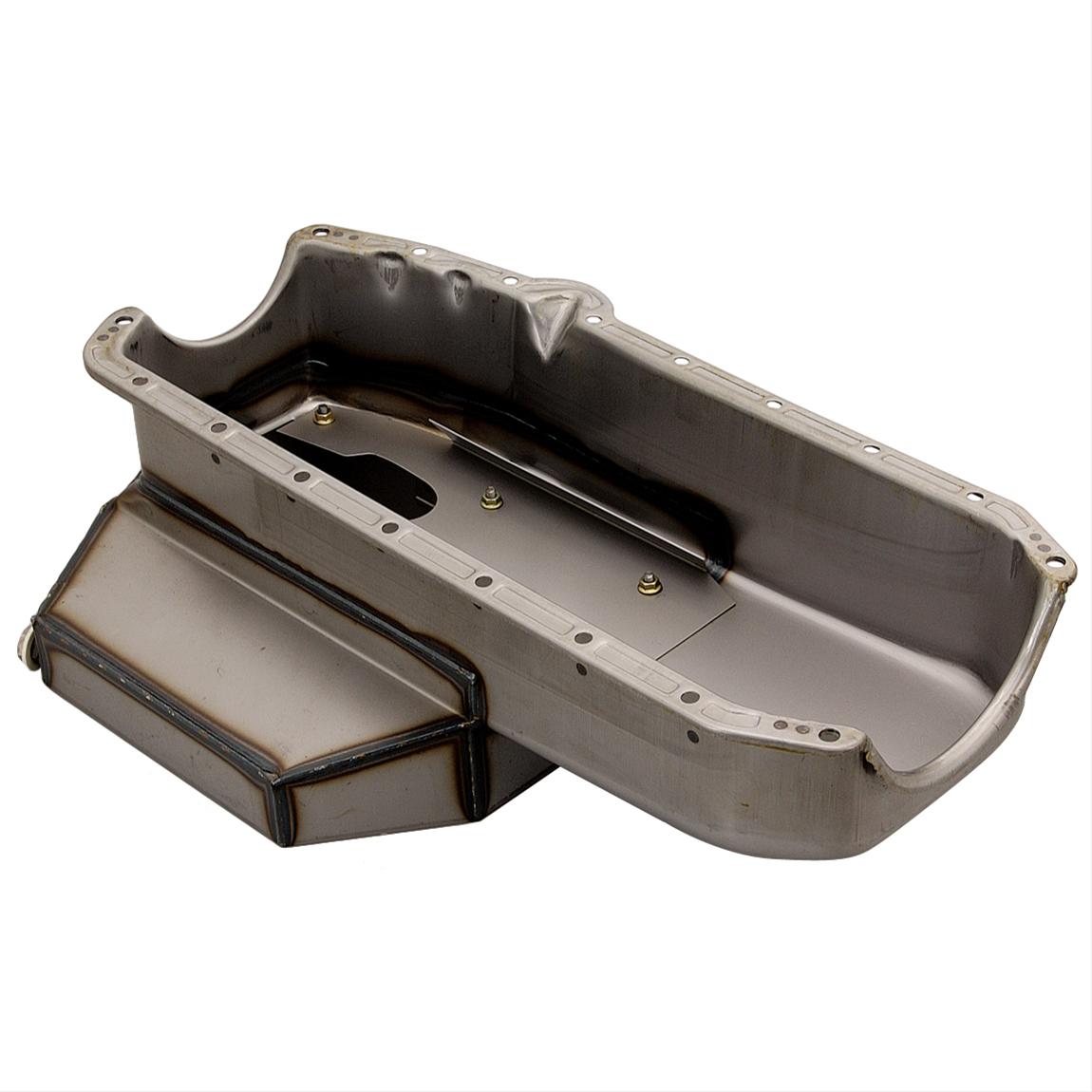
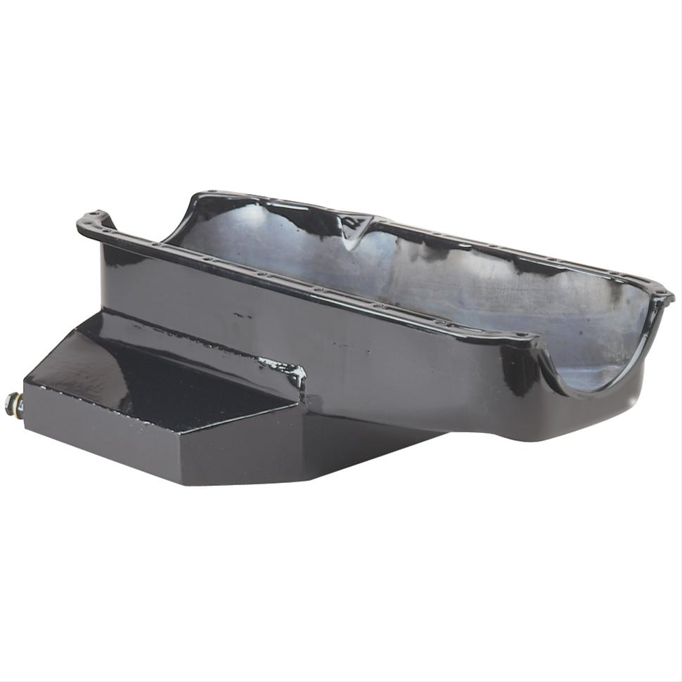
427 tuned port
FIRST intake, EH ported
Dart SHP block, 4” stroke X 4.125 bore
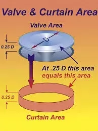
223cc CNC ported heads, 10.25 CR
1 3/4” LT headers
Car will be running a gen 4 ECM, tuned by me with HP tuners
Want a cam that idles like stock. Intake tuned to a 3500-4000 RPM torque peak. ZL1 converter in a built 6L80E with a 3.08 rear gear. Billet step nose cam core, small base circle, LS firing order.
Yes I know it’ll make a gajillion ft lbs of torque. That’s the point and the reason for the high gear (and cruise RPM). Car will run fat rear tires and an IRS, though I’m sure that won’t help that much…
Everyone wants to cut big cams. I want an efficient and specific cam that I cannot find on the shelf. If anyone knows who has experience in this arena, I’m all ears…
Just a few details:
427 tuned port
FIRST intake, EH ported
Dart SHP block, 4” stroke X 4.125 bore
223cc CNC ported heads, 10.25 CR
1 3/4” LT headers
Car will be running a gen 4 ECM, tuned by me with HP tuners
Want a cam that idles like stock. Intake tuned to a 3500-4000 RPM torque peak. ZL1 converter in a built 6L80E with a 3.08 rear gear. Billet step nose cam core, small base circle, LS firing order.
Yes I know it’ll make a gajillion ft lbs of torque. That’s the point and the reason for the high gear (and cruise RPM). Car will run fat rear tires and an IRS, though I’m sure that won’t help that much…
Everyone wants to cut big cams. I want an efficient and specific cam that I cannot find on the shelf. If anyone knows who has experience in this arena, I’m all ears…