Let’s Tune This Engine

Is there a way to do that on the car ?

Yes... I would start with the one that was bent first. use one of your old push rods and install it. look for binding on the retainer and rocker,
then rotate engine to full valve open slowly and watch for any binding anywhere. Measure the gap at the bottom of the spring coil when valve is
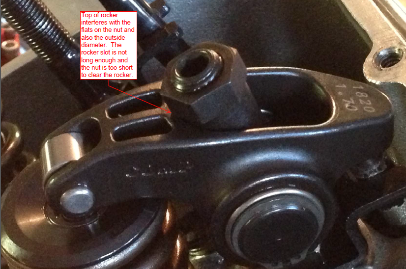
open. I believe you should be no less than .060 between the coils. Check to see if your roller is not off the valve also. look at your guide plate and see if the push rod is rubbing on it or the head itself. Check to see where the nut on the stud is. It might be that it is wedging against the slot in the rocker.

It's a slow and methodical process, but it needs to be done. There was an interference somewhere that bent that pushrod.

Worst case senerio is the valve smacked the piston...but I would think you would have had more bent push rods if that were the case.
 
Thanks. I should have thought of feeler gauges. I was using stacked paper :rolleyes:

I doubt I’d have 200 psi of compression if worst case scenario happened. I didn’t hear any odd noise either.

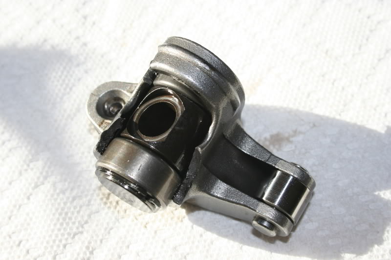
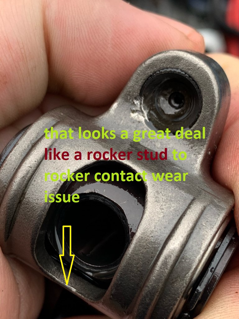
Based on the dent on the rocker, next to the cup, I’m betting the rocker twisted around and the pushrod was shoved into it.

Nonetheless, when the engine was running I did hear clicking no matter what I did to adjust the valves. I also got that vacuum reading vibration indicating a valve was not seating properly. None of this I got with the engine prior to the cam swap. I’m going to recheck the pushrod guides.

Also the ignition
 
Last edited:
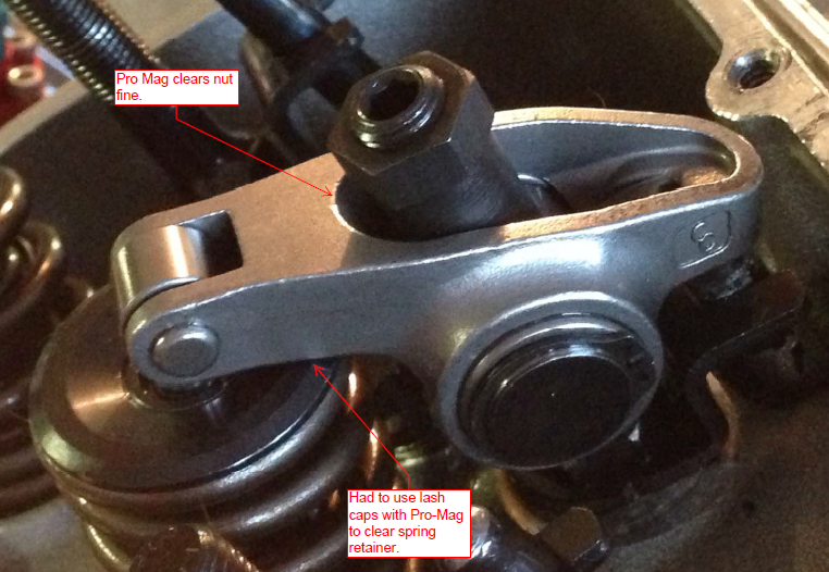
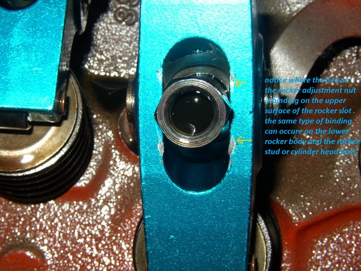
some of the most common areas that gets over looked or ignored in some cases is the rocker nut clearance in the rocker body , or the lower rocker slot binding on the rocker stud
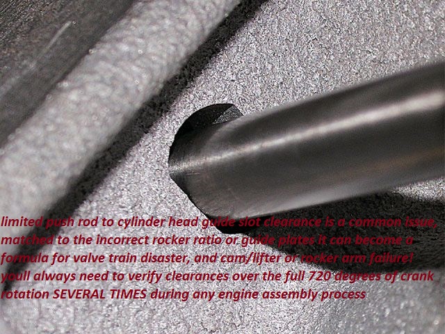
pushrods binding near full lift in the cylinder head slot or the push rod guides is also common,
if your hearing metallic clicking noise at idle, somethings binding or at least touching where it should not be
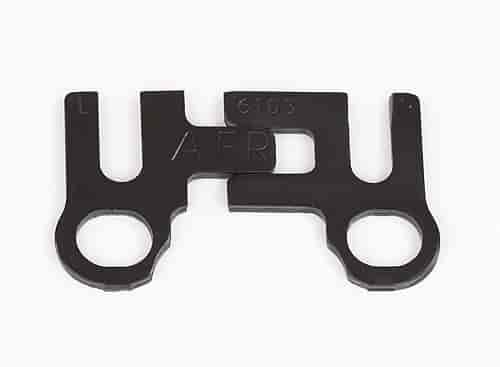
sguide_plate.jpg

http://garage.grumpysperformance.com/index.php?threads/valve-train-clearances-and-problems.528/

http://garage.grumpysperformance.co...-pushrods-and-check-info-you-might-need.5931/

http://garage.grumpysperformance.com/index.php?threads/rocker-push-rod-wear-issues.9815/

http://garage.grumpysperformance.co...ength-change-valve-to-piston-clearance.16408/

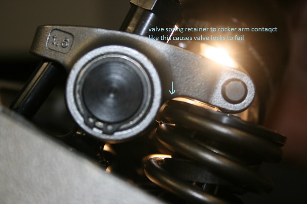
and the rocker contacting the retainer,
retain6.jpg


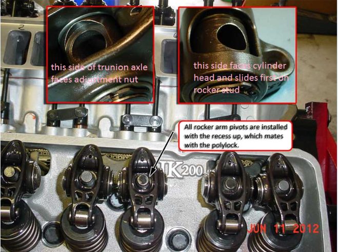
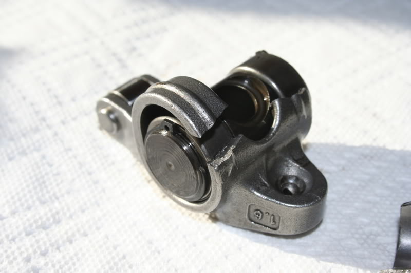
SOME ROLLER ROCKERS CAN AND DO BIND ON ROCKER STUDS, or rocker adjustment nuts, youll need to check carefully
rpo1x.JPG

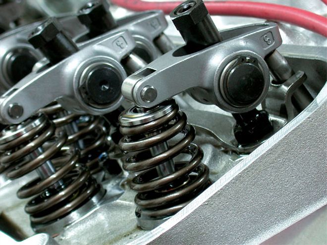
some roller rocker too retainer combo clearance issues cause problems easily solved with beehive springs and smaller retainer diameters

beehivesprcl.jpg


the POLY LOCKS that are used with most roller rockers AND ROLLER ROCKER SIZES, (come in a variety of lengths AND DIAMETERS AND THREAD SIZES) so you might find you need tall valve covers to allow clearance BUT in most cases swapping to shorter poly locks reduced that problem from mandating taller valve covers, be aware that the outside diameter of the locks is a darn important factor in allowing the rocker to reach full potential lift!
it should be obvious that youll need to carefully check clearances over the full rotation and lift in several areas if you chance valve train components and retainer to rocker and internal rocker clearance slot to poly lock are two of many potential places the valve train may bind if theres not the correct clearance

rockerh1.png

rockerh2.png


rockerbin.jpg

rockertrunion1.png


rockflr2.jpg

rockflr1.jpg
 
Grumpy... YOUR THE MAN!!! Those pictures and explanation are priceless.
The 4th to the last pic is a very common issue I have seen...where the points of the nut make contact with the rocker..It actually happened to me.
Thou it is a very easy correction.. but one that must be looked for.

These type of explanation's are what make this site so awesome.!
 
Delete
 

Attachments

  • 09F85E75-7426-4FD2-B881-FC46DFC3FDFA.jpeg
    09F85E75-7426-4FD2-B881-FC46DFC3FDFA.jpeg
    118.4 KB · Views: 9
  • 361AE0FC-9911-4B58-8349-89D8BA4848DA.jpeg
    361AE0FC-9911-4B58-8349-89D8BA4848DA.jpeg
    123.5 KB · Views: 11
  • 140F3922-D923-48C8-888C-B1DC27F84E5D.jpeg
    140F3922-D923-48C8-888C-B1DC27F84E5D.jpeg
    112.1 KB · Views: 9
Last edited:
I THINK I might have found it.

I went though all the rockers, pushrods, retainers, keepers, guide plates, poly locks and could not find any evidence of contact other than the small amount of damage next to the cup of the rocker of intake. This is where the pushrod with the loose poly lock got banana-ed.

F35EDB57-5272-4FF3-A6E3-0D37B3FCC822.jpeg

I checked for coil bind and rocker to retainer clearance and there seems to be a lot of clearance. This is maximum lift.

6EF6141F-94AC-4F0A-8A54-156F254AC24D.jpeg


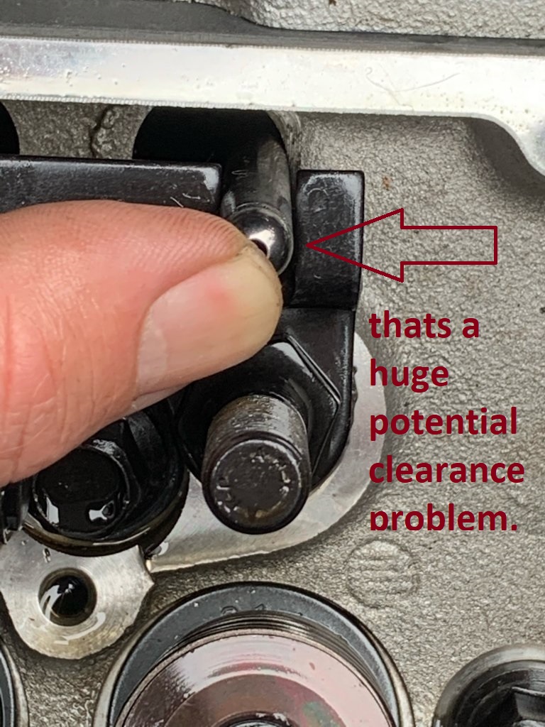
Then I think I finally caught it. I think this pushrod is binding between the head and the guide plate... but only when the rocker is installed and lifts the rod up like I am doing with my thumb.


2E201678-CDF0-4D15-9644-5C715816C8D8.jpeg

With the rocker not installed and the rod resting close to the stud... it is fine. That’s why I’d didn’t catch it. With the rocker installed, it binds. This is intake 5.

When all the rockers are installed loosely, they all have some play... except for intake 5.

Why is this happening now and not with the old cam ? The lifters are taller. The rods are shorter. Maybe there’s a tiny, but critical change in geometry ? Dunno.

The clacking I heard with the stethoscope was distinct. I do hope that this is the cause. It was in this side and wouldn’t go away no matter how I tried to adjust the preload.
 
That last pic with your finger on the pushrod shows that the pushrod is rubbing on the head! That would definetly
cause the push rod to bend and slip the cup. Your going to have to clearance that head if that rod is that close.

Also, the second to the last pic indicates the poly lock might be bound up on the backside of the slot in the rocker. Double check..

Are those new guide plates? Check to see if the guide plate is holding the rod out of alignment.
If it is, you can slot the hole in the plate where the stud goes through. This will give you
some room to adjust the plate. Or you could move the push rod slot itself by grinding one side of the slot and welding the other side of the slot . ONLY do this if it showing that the slot is out of location . Or use a different guide plate all together.

From the pic though.... I think that some bit of shaving must be done to the head.
 
Last edited:
Fixed. There was enough movement, more than enough, to carefully center the rockers and clear the head. I hope this was the issue. I think it’s possible, by not certain.

The new pushrods get here on Monday.

Oh and I rechecked the poly lock clearance in the rocker. It looks good.
 
Awesome. It pays to spend some time double checking everything..Glad you had the room for the adjustments.
 
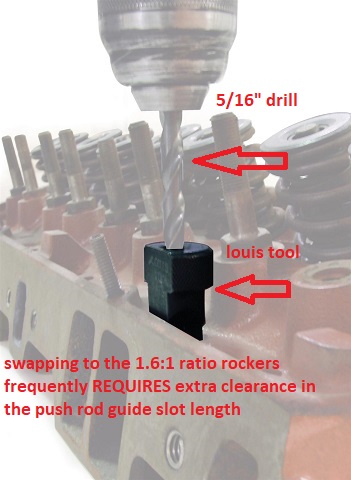
You can buy guide plates that are even more adjustable, I don't have a picture or a web address, but I think Grumpy does have that information. He posted it on my thread when I was building my engine. Mine is a 400 also, it seems you get into these issues when you go above the standard 1.5 rocker ratio, if I am right yours are 1.55.
 
I’m not reading all the posts in between although the “lash” on a hyd cam is set cold.
You MUST be on the base of the lobe to set the lifter properly with Comps instructions.
Remember there are standard hydraulic rollers and short travel rollers.
Once on the lobe base...
Back off the lifter until you have up/down play in the pushrod then tighten the rocker until you can spin the pushrod but “0” up/down movement. For short travel lifters you add 1/8 turn.
Standard lifters.. 1/2 turn.
Follow the process from Comp exactly and you will be set for a long while.

Now that you have the cam in did you verify your spring clearances?
Do you have enough clearance for the new lift?
Coil bind or perhaps is the retainer hitting the oil seal?
 
I just clicked on the link for your rollers. I know this is a SBC but on BBC there are retrofit lifters for motors that did not come from the factory with rollers.
You should check that out with Comp.
 
I agree with Grumpy, you'll need at least 1/16 inch minimum clearance all the way through the lift of the lobe and movement of the valve. I used the adjustable guide plates Grumpy showed above. They got most of it, but through the full movement of the valve about halfway the clearance closed up and I had to relieve the head some with a die grinder to have the clearance through the full stroke of the pushrod.
 
The lift on this cam isn’t too radical. Eyeballing I can tell the gap between the coils is way over 1/16, easy.

I did set the lash following the steps of the SA book. Quite frankly I’m more comfortable using the EOIC method.

I’ll be doing that and checking all the pushrod-to-guide plate clearances.

Once the lash is done, I’m going through the ignition again. I suppose it is possible that it’s misfiring. On the other hand the plugs look good.
 
Looking at the first photo it it’s the contact with the cyl head that concerns me more. Draw a virtual line through the valve stem and the stud... look the pushrod may be in the correct place and either the casting or the location of the stud is wrong.
 
I see what yer saying. Way past dark here. Il check that out tomorrow.
 
Back
Top