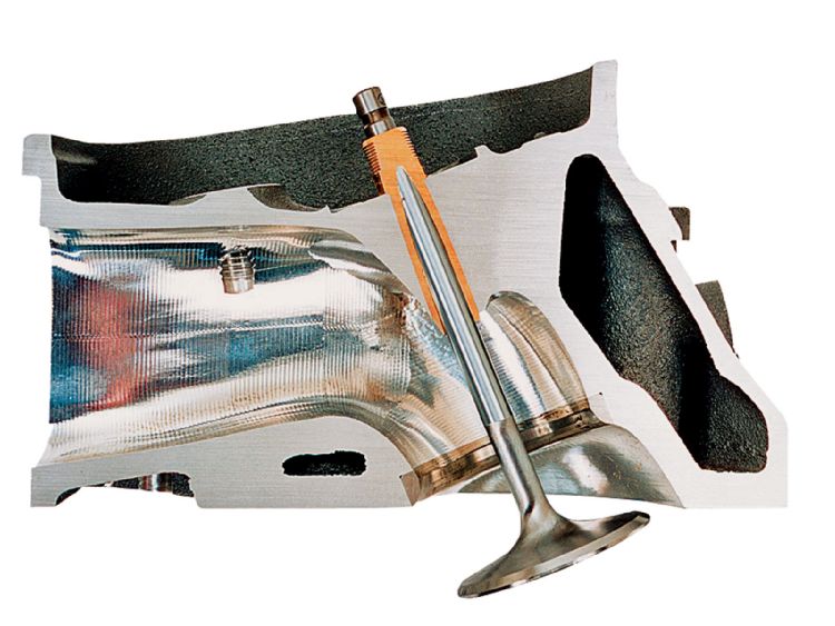
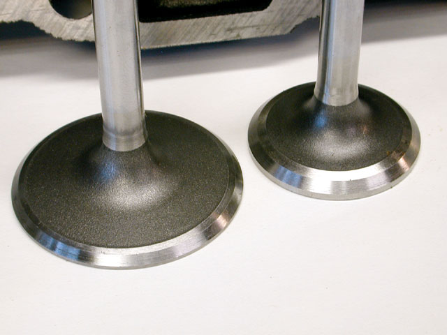
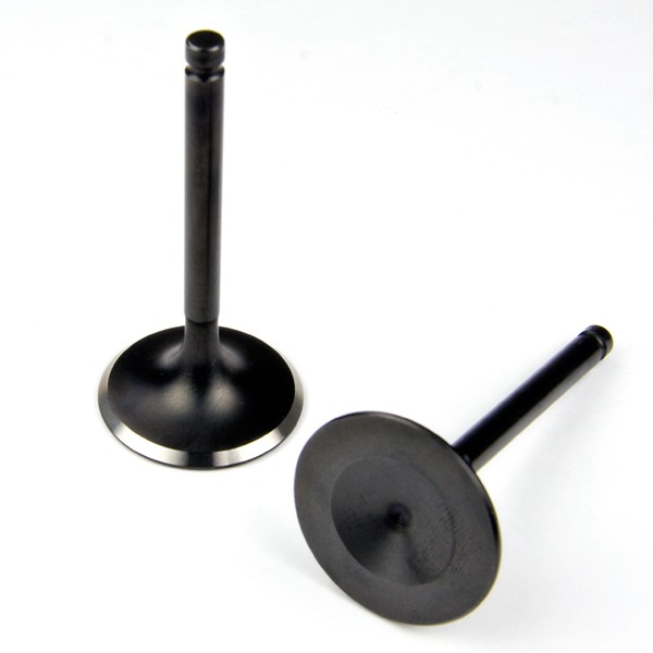
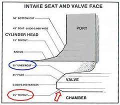
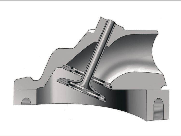
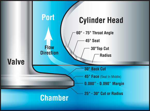
valve seat angles and the actual angles cut on the valve edges them selfs and how you have the area under the valve in the port bowl area cut and blended has a marked effect on your engines air flow.
When you drop off heads to be machined, its MANDATORY you are very clear and specific about what you want done,
and establish both the expected total cost and parts finished date or,
delivery time frame with the machine shop before work is started.
failure to do both almost always results in mis-understandings,
lower quality work, missed machine work being done, or a total failure of the machinist do do what you intended.
you can't for example say, "DO A VALVE JOB"
you need to be specific, saying I want a 3 angle or 5 angle valve job , what the angles are, what you want in valve mads, if they are too add new valve seats if required , test and replace all the valve springs, set the installed valve spring height at lets say 1.78" and a valve spring seat pressure falls in the expected range of of 180-193 lbs install new valve seals, verify the valve guide clearance back cut angle on the valve etc.
YES THIS WILL ALWAYS COST YOU MORE THAN A TYPICAL HIT OR MISS ONE ANGLE VALVE JOB< IT IT WILL GENERALLY RESULT IN A MUCH HIGHER QUALITY WORK AND MORE ATTENTION TO THE DETAILS


include diagrams and written instructions where needed
garage.grumpysperformance.com
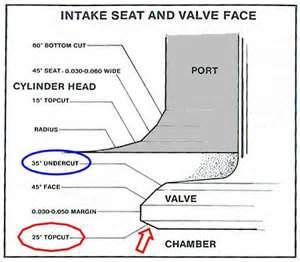
as a general rule air flowing over a change in angle across a surface tends to become noticeable more turbulent, if the change in angle exceeds about 15 degrees, and that tends to reduce flow. so if you look closely you see a tendency to cut the seat on a port in 15 degree steps or less.
I know from multiple experiences, that a throat and bowl clean up, mild combustion chamber contour smoothing, and a well done multi angle valve job, and upgrading to the correct valves and valve springs can very easily allow well over 1000 higher rpm and 30 plus extra horse power on a BBC.
when I first started building engines it was rather common for guys to drop heads off at the local machine shop and have the heads rebuilt and a valve job done, this consisted in most case in getting a 3 angle valve seat cut and a two angle cut on the valves and checking the guides and seals for wear and replacing them if it was required.
but after a few years of reading and doing some research I found I got much better results driving over a 120 miles to a PERFORMANCE machine shop that charged about twice as much for a valve job, but they cut three angles on the valves and 5 angles on the seats and cleaned and blended the bowl area under the valves, it was not unusual to see a car run one or two tenths faster in the 1/4 mile once that was done, compared to the stock, as cast factory heads, on a muscle car.
ccing the heads is always a good idea as is smoothing the combustion chamber and removing casting irregularities,
in fact one secret I had was building big block Chevy heads and having that shop upgrade the valves to the larger manley or TRW, valve sizes and cut and blend the seats, a set of BBC heads that came with 2.06 (oval port heads) 0r 2.19 intake valves (rectangular port heads)could usually accept the larger 2.19-or 2.30 intakes after some rather expensive machine work and having new valve seats installed, and 1.88" or even 1.94"exhaust valves VS the stock valves and some porting work.
the change in power was usually noticeable.
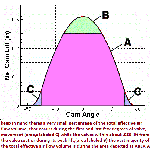
keep in mind the valve starts flowing at least some airflow as the valve lifts off the seat but generally not a significant amount until the valves at least .006 off the seat and by .050 lift its generally flowing enough to measure easily, but keep in mind that even at only 1000rpm those valves are going thru repetitive cycles from fully seated to fully open and back to fully seated 8.3 times PER SECOND , and at 7000 rpm its 58 times PER second, so the time a valve remains at any specific lift is very minimal
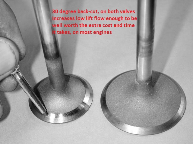
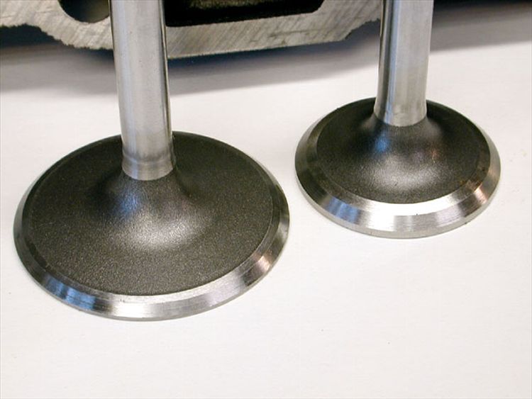
in fact a simple change like a 30 degree back cut on a set of big block valves is usually worth an additional 10-15 hp, at very minimal cost and double angle back cuts have occasionally shown a bit more, flow especially at lower valve lifts.
Remember the valve is at minimal valve lift twice in each cycle while its only at peak lift once.
the port area under the valve seat must be smoothed and blended into the seat area to maximize air flow , but you generally don,t want the seat throat to exceed about 88%-90% of the valve diameter, or both flow and valve heat transfer to the valve seat is compromised.
we also learned that there were valves with longer valve stems and smaller diameter and lighter weight valves stems that would allow taller spring installed heights and larger springs for improved clearances, if you were willing to use custom length push rods and verify your valve train clearances and geometry, etc.
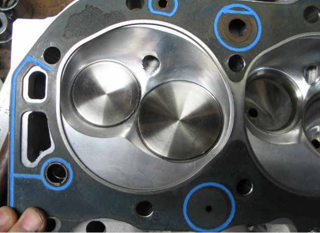
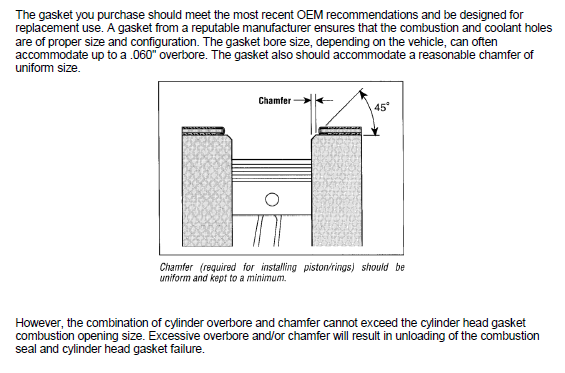
head gaskets are rarely completely round, nore are combustion chambers
you,ll want to place a head gasket you,ll use on the heads and mark the area inside the opening as the only areas you can change,
(notice the gasket fire ring is NOT a perfect circle like many people assume)
ideally you,ll want to un-shroud the valves while opening up the combustion chamber volume, but not extend the combustion chamber past the front edge of the gasket fire ring as that usually causes gasket failure
http://garage.grumpysperformance.com/index.php?threads/ccing-my-heads.14187/
http://garage.grumpysperformance.com/index.php?threads/iron-vs-aluminum-heads.389/#post-31684
http://garage.grumpysperformance.com/index.php?threads/multi-angle-valve-job-related.3143/#post-8387
http://garage.grumpysperformance.com/index.php?threads/port-speeds-and-area.333/
http://garage.grumpysperformance.co...r-piston-dome-or-port-volume.2077/#post-60554
![[IMG]](/proxy.php?image=https%3A%2F%2Fweb.archive.org%2Fweb%2F20151002214931%2Fhttp%3A%2F%2Fwww.grumpysperformance.com%2Fvgd4.jpg&hash=fc8807777541b8d743058c878b4f8a6e "[IMG]")
![[IMG]](/proxy.php?image=https%3A%2F%2Fweb.archive.org%2Fweb%2F20151002214931%2Fhttp%3A%2F%2Fwww.grumpysperformance.com%2Fporting%2Bvalve_area.jpg&hash=7731b80d345aee14ba360224448732d2 "[IMG]")
![[IMG]](/proxy.php?image=https%3A%2F%2Fweb.archive.org%2Fweb%2F20151002214931%2Fhttp%3A%2F%2Fwww.grumpysperformance.com%2FPorts.jpg&hash=122368aa696a2c36b220bd53642fc638 "[IMG]")
![[IMG]](/proxy.php?image=https%3A%2F%2Fweb.archive.org%2Fweb%2F20151002214931%2Fhttp%3A%2F%2Fwww.grumpysperformance.com%2FPortMatch02.jpg&hash=3ef0d922ac022a108018672bd8c12ec4 "[IMG]")
![[IMG]](/proxy.php?image=https%3A%2F%2Fweb.archive.org%2Fweb%2F20151002214931%2Fhttp%3A%2F%2Fwww.grumpysperformance.com%2FPortMatch03.jpg&hash=c8bf8d7bf4beb8dfaf9729d334c6a748 "[IMG]")
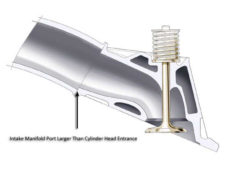
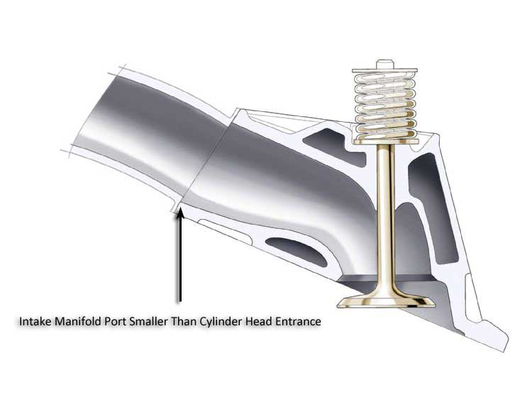
PORT MATCHING THE INTAKE RUNNER EXIT TO THE CYLINDER HEAD PORT ENTRANCE USUALLY HELPS REDUCE RESTRICTIONS TO FLOW RATES, AND REDUCES FUEL/AIR DISTRIBUTION ISSUES
http://garage.grumpysperformance.com/index.php?threads/how-to-lap-valve-seats.1159/#post-2362
http://www.alexsparts.com/
http://www.summitracing.com/parts/man-11730-8
http://www.summitracing.com/parts/mil-45135-8
http://www.summitracing.com/parts/mil-45117-1
http://www.summitracing.com/parts/man-11847-8
ideally your port cross sectional area doesn,t change suddenly
valve seat and back face angles ,valve diameter and valve lift and duration effect the flow thru the curtain area
it should be rather obvious that youll need to know the exact distance the piston deck sits at TDC ,above or below the block deck surface and the valve notch recess or pop-up dome volume of the piston to do accurate quench or compression calculations
valve seat and back face angles ,valve diameter and valve lift and duration effect the flow thru the curtain area
keep in mind that valve may be forced off its seat, too full lift and re-seating 50 plus TIMES A SECOND at near 5500 rpm, so theres very little TIME for gases to move through the very restrictive space between the valve seat and valve edge
Calculating the valve curtain area
The following equation mathematically defines the available flow area for any given valve diameter and lift value:
Area = valve diameter x 0.98 x 3.14 x valve lift
Where 3.14 = pi (π)
For a typical 2.02-inch intake valve at .500-inch lift, it calculates as follows:
Area = 2.02 x 0.98 x 3.14 x 0.500 = 3.107 square inches
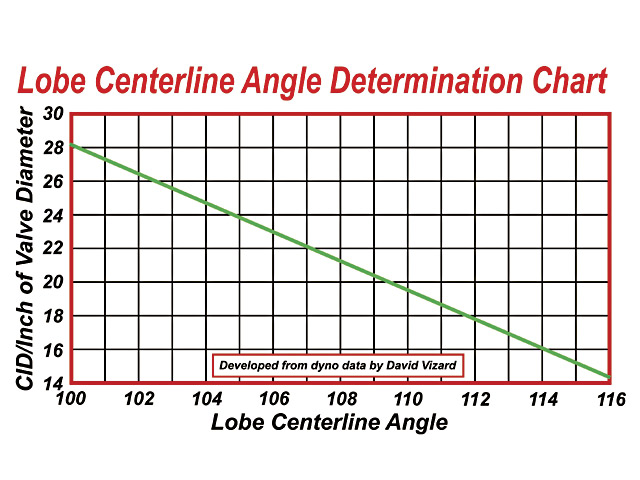
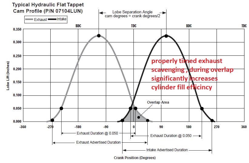
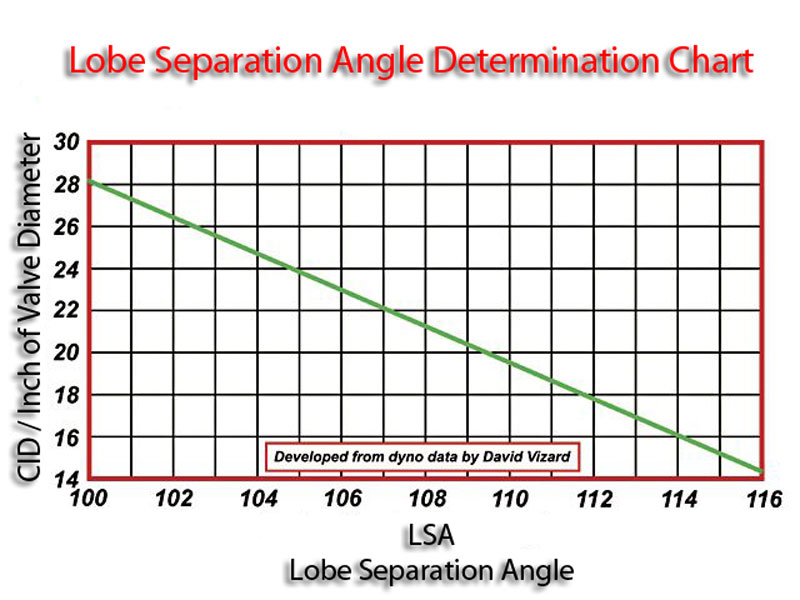
wider LSA smooths out the idle but it reduces overlap, the increased overlap tends to allow cylinder fill at a bit higher rpm and it also tends to kill off a bit of low rpm torque
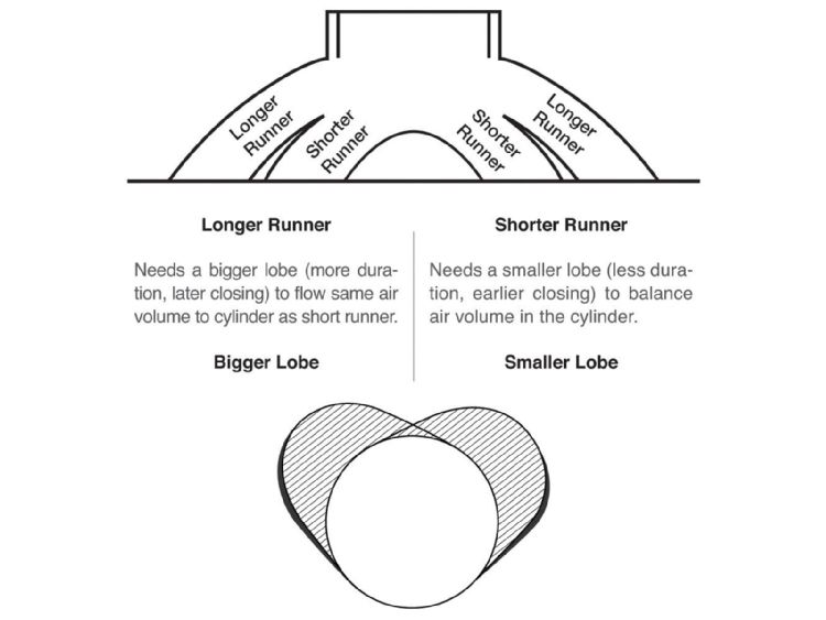
keep in mind a cam simply controls PART of the complex sequence of mechanical , inertial flow,and thermal events that effect the engines cylinder filling exhaust scavenging efficiency , the head flow, intake design, efi or carb manifold, plenum and runners, exhaust header design, primairy and collector size and length, exhaust back pressure the fuel air ratio, the ignition timing, and the drive train gearing, the engine displacement, combustion chamber shape valve sizes, the valve seat angles and several other factors have significant effect on the power your likely to see and at what rpm, its available.
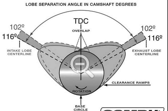


The following tables illustrate how variations in lobe separation angle and cam
timing will effect the behavior of the engine in which the camshaft is installed.
EFFECTS OF ALTERING CAMSHAFT TIMING
Advancing.......................................... Retarding
Begins Intake Event Sooner................. Delays Intake Closing Event
Open Intake Valve Sooner ........................Keeps Intake Valve Open Later
Builds More Low-End Torque................. Builds More High-RPM Power
Decrease Piston-Intake Valve Clearance Increase Piston-Intake Valve Clearance
Increase Piston-Exhaust Valve Clearance Decrease Piston-Exhaust Valve Clearance

keep in mind any valve clearance recessed areas must have the areas shrouding flow blended to increase rather than restrict air flow and to reduce the potential for detonation that sharp exposed edges tend to have
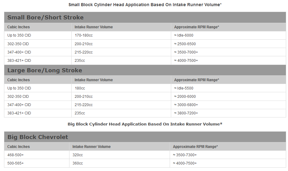
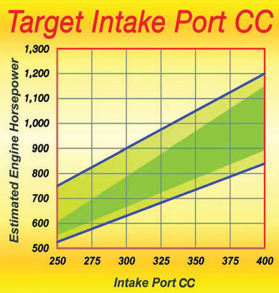
PROJECTED HP PORT VOL.
MIN - MAX MIN - MAX
350 - 400 140 -160
400 - 450 160 - 180
450 - 500 180 - 200
500 - 550 200 - 220
550 - 600 220 - 230
600 - 700 230 +
This chart gives a good working guideline as to the intake port volumes to target for a small-block Chevy. Remember, a little too small is much better than a little too big. If the port volume of the heads you have seems a little too big, go for all the compression ratio the fuel intended will stand, as this will, to some extent, compensate.
READ THRU THIS LINK
http://www.circletrack.com/enginetech/1 ... ch_engine/
http://garage.grumpysperformance.com/index.php?threads/how-to-lap-valve-seats.1159/#post-2362
USE THE CALCULATORS to match port size to intended rpm levels... but keep in mind valve lift and port flow limitations[/color]
http://www.wallaceracing.com/runnertorquecalc.php
http://www.wallaceracing.com/ca-calc.php
http://www.wallaceracing.com/area-under-curve.php
http://www.wallaceracing.com/chokepoint.php
http://www.wallaceracing.com/header_length.php
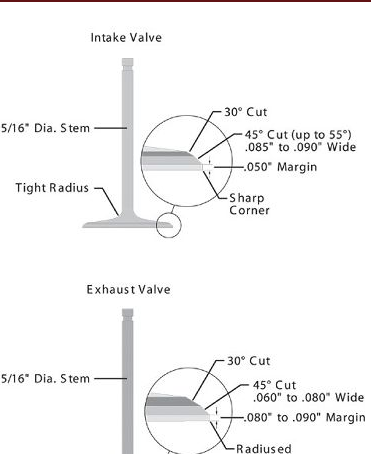
Most of the machinists prefer an intake-seat width of 0.040-0.060 inch. Narrower seats generally improve flow but are also less durable. Narrow seats work best on drag-race applications where the engine is freshened often. Harder seat materials (e.g., induction-hardened seats) allow you to run slightly narrower seat widths than in the past while retaining excellent durability. Since exhaust valves operate at extreme temperatures, they require a wider seat to conduct heat away from the valve through the seat. Most shops specify 0.060- to 0.080-inch seat width for the exhaust side.
http://www.chevyhiperformance.com/techa ... z2bm45kKdb
http://www.stockcarracing.com/techartic ... to_04.html
http://garage.grumpysperformance.co...olishing-combustion-chambers.2630/#post-50247
http://worldtracker.org/media/library/C ... pter23.pdf
as a general rule you'll find single plane intakes on a SBC generally work best on engine combos with at least a 245 duration cam at .050 lift and with 10.7:1 or higher compression and solid lifter cams that can operate efficiently in the 5500rpm-7000rpm PLUS power band and geared to operate in that same 5500rpm-7000rpm PLUS power band most of the time.
this also requires a short block assembly designed to operate in that upper rpm band, now as the engine displacement is increased, like in the larger displacement BBC engines port and runner air flow speeds will also increase so the effect is that a larger BBC engine can use more, or longer cam duration at a given rpm band, due to its larger cylinder volume to valve curtain area requiring more time, for effective cylinder fill and scavenging .
thus a 2.02 valve sbc reaches max flow near .505 lift
thus a 2.19 valve BBC reaches max flow near .5475 lift
Calculating the valve curtain area
The following equation mathematically defines the available flow area for any given valve diameter and lift value:
Area = valve diameter x 0.98 x 3.14 x valve lift
Where 3.14 = pi (π)
For a typical 2.02-inch intake valve at .500-inch lift, it calculates as follows:
Area = 2.02 x 0.98 x 3.14 x 0.500 = 3.107 square inches
For a typical 2.19-inch intake valve at .550-inch lift, it calculates as follows:
Area = 2.19 x 0.98 x 3.14 x 0.550 = 3.714 square inches
a typical 383 sbc with that .500 lift cam, has 47.875 cubic inches of volume in a single cylinder, divide that by the curtain area of 3.107 and you get 15 cubic inches of cylinder volume for each square inch of valve curtain
a typical 496 BBC with that .550 lift cam, has 62 cubic inches of volume in a single cylinder, divide that by the curtain area of 3.714 and you get 16.69 cubic inches of cylinder volume for each square inch of valve curtain, or about 11% less available air flow even with the larger valve and higher lift cam, to compensate use of a tighter LCA is frequently used to allow a longer, and more effective cylinder scavenging time frame in the big block combo

http://garage.grumpysperformance.com/index.php?threads/port-speeds-and-area.333/
http://garage.grumpysperformance.co...alves-and-polishing-combustion-chambers.2630/
http://garage.grumpysperformance.co...lsa-effects-your-compression-torque-dcr.1070/
THERES A GREAT DEAL MORE INFO IN THE LINKS AND SUB LINKS AS USUAL
http://zhome.com/ZCMnL/PICS/detonation/detonation.html
http://rlengines.com/Web_Pages/Serid_10 ... chine.html
http://www.superchevy.com/how-to/engine ... w-testing/
http://www.superchevy.com/how-to/engine ... omparison/
http://www.reidsautomotive.com/Cylinder ... vices.html
http://www.strokerengine.com/SBCHeadsFlow.html
http://www.chevyhiperformance.com/techa ... ve_angles/
http://www.popularhotrodding.com/tech/0 ... to_06.html
http://www.enginebuildermag.com/Article ... gines.aspx
http://www.enginebuildermag.com/Article ... pdate.aspx
http://www.aera.org/engine-professional ... echnology/
http://www.precisionenginetech.com/tech ... ns-part-2/
http://www.carcraft.com/techarticles/11 ... lve_angle/
http://www.allpar.com/fix/holler/valve-prepping.html
http://www.enginebuildermag.com/Article ... _jobs.aspx
http://www.chevyhiperformance.com/techa ... ewall.html
http://www.popularhotrodding.com/tech/1 ... ewall.html
http://www.carcraft.com/techarticles/11 ... ewall.html
http://www.enginebuildermag.com/Article ... _flow.aspx
By Larry Carley
Page 1 of 2
Next Page >>
Larry Carley
No one knows airflow better than the legendary Joe Mondello, who rose to fame back in the 1960s for his race-winning cylinder head work.
“Back in those days, we didn’t have flow benches to test our work. Our test bench was the drag strip. If a modification worked and made the car run faster, that’s what we used. If it didn’t work and the car ran slower, we went back to Plan A or tried something else.”
Today, it’s an entirely different situation. Mondello’s tech center in Crossville, TN, uses state-of-the art equipment to test and verify cylinder head modifications. Mondello says most of the development work he does today involves using a wet flow bench, a machine that mixes an ultraviolet dyed liquid mist with air to simulate what actually happens to the air/fuel mixture as it flows into the combustion chamber.
A dry flow bench measures airflow in cubic feet per minute (cfm), which is useful information for evaluating how changes that are made in the configuration of a port or the angles on a valve seat affect airflow at various valve lifts. But a wet flow bench shows you how those changes affect turbulence in the air/fuel mixture, and where fuel may be separating or puddling in the valve bowl, seat area and combustion chamber.
In other words, a wet flow bench shows you things you can’t see with a dry flow bench. It also allows you to verify the effect any modifications you’ve made are having on the air/fuel mixture that might hurt performance because of turbulence, fuel separation or puddling in the combustion chamber. The basic idea is to make sure the air/fuel mixture stays mixed and disperses evenly as it enters the combustion chamber so it will burn properly and produce maximum power.
“It’s important to remember that the engine is the primary guide for what kind of modifications actually produce more power, not just airflow numbers alone,” says Mondello. “That’s where the wet flow bench has really helped. The results we see on a wet flow bench are confirmed on the dyno and on the track. We can tear down an engine and look at the patterns on the pistons to confirm what the wet flow bench already told us.”
How Seat Angles Affect Airflow
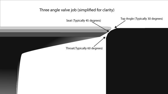
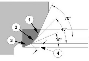
Generally speaking, the more angles there are on the seats, the better the seat flows. A stock valve seat with only a single 45 degree angle cut on it will have a sharp edge just above and below the area where the valve sits on the seat. As the valve starts to open and air begins to flow past the valve, the abrupt change in angles create turbulence that reduces air velocity and flow.
This abrupt angle can also cause the air/fuel mixture to separate. So cutting another angle above the primary seat and a third angle below the seat helps smooth out the airflow. That’s why a traditional 30-45-60 degree three-angle valve job produces more power than a stock valve job. The extra angles help the air turn the corner so-to-speak, which reduces turbulence to improve air velocity and flow. It also lessens air/fuel separation to improve combustion, too.
Mondello says the traditional three-angle valve job is old hat in today’s performance engines. A 30-45-60 degree three angle valve job is still better than a single 45 degree cut on the valve seats, but it can’t come close to what’s possible by optimizing the valve seat profile with additional angles.
“A few weeks ago, we had three engineers from Harley-Davidson Screaming Eagle Division here for a technical session. They just designed a new 103 head and a 110 head and were quite proud of how well it flowed. We took their head, and in three days time we improved the airflow 52 cfm over their initial design. Out of the 53 cfm that we picked up, 25 cfm was due to changes we made in the valve seat angles alone. That shows you how critical valve seat angles are for maximizing airflow and power,” says Mondello.
“Many cylinder head manufacturers are using single point cutters on a CNC machine to cut their valve seats, and they are not spending much time blending the chambers or doing all the things they really should be doing to make the valve job work properly. That’s actually good for our business because we rework a lot of these cylinder heads, especially Harley heads,” Mondello explains.
The most important part of building any performance cylinder head is cutting the angles on the seats, Mondello says. “Over the years, many engine builders have relied on the basic 30-45-60 degree three angle cutter. They think they can use the same three seat angles on every cylinder head they do – but that’s not true. The angles that work best will vary depending on the application.”
Mondel says he prefers to use a fairly steep top angle, because a steeper angle improves airflow. “When the valve first opens, a steeper angle allows better flow into a combustion chamber that has hills and valleys and is not perfectly flat. If you have a 30 degree top angle, the air coming off that seat will be turbulent and you’ll get separation between the air and fuel which hurts power. Increasing the angle allows for a better transition from the seat into the combustion chamber. It’s more efficient, offers less resistance and makes more power.”
Mondello recalls that in his early days of reworking cylinder heads, he discovered that four angles often provided the best airflow, throttle response and power. The four angles he used were 45 degrees for the primary seat, a 33 to 37 degree top cut, a 58 degree undercut below the primary seat, and a 70 degree cut below that made with a hand-driven reamer. Using these angles can often improve airflow 8 to 15 cfm or more.
Finding the angles that work best with a given cylinder head, camshaft and valve combination requires a lot of time on both a wet and dry flow bench, as well as dyno testing and track time. A lot of small shops don’t have a flow bench or a dyno to do development work and testing on their engines. They have to rely on experience and feedback from their customers to determine what works on the track or drag strip. Consequently, they may not be getting as much power out of their engines as they could.
Special Valve Seat Cutters
To address this issue, Mondello has put his nearly 50 years of experience in reworking performance cylinder heads into his own line of high performance valve seat cutters. The “Joe Mondello Signature Series Infinite Flow Valve Seat Cutters” feature all of Mondello’s tricks for improving airflow, velocity and power. The valve seat cutters feature multiple valve angles that are proven to significantly improve airflow and power over a single angle or three-angle valve seat cutter. Mondello says his multi-angle cutters typically increase airflow 10 to 20 cfm by just adding and changing the angles on the valve seats.
However, Mondello urges caution and care when using a cutter that is designed for a certain application. “My exhaust seat cutters go from a primary seat into a full radius below that seat, but they’re only recommended for exhaust seats, not intake seats. A lot of guys will also use them to cut the intake valve seat because it shows an 8 to 10 cfm increase in airflow on a flow bench. But when you look at the actual airflow pattern on a wet flow bench, the profile that was developed for the exhaust seat causes bad fuel shear and turbulence in the valve bowl and seat area. That’s why I offer different profiles for the intake seats.”
Of course, putting a radius on the intake seat is nothing new, and a lot of guys have been doing it for years because it increases airflow. But Mondello says bigger airflow numbers don’t necessarily translate into more power. It depends on what happens to the air/fuel mixture as it enters the combustion chamber.
“My valve seat cutters are designed to improve airflow, throttle response and horsepower, and they can be used on heads for street cars as well as a race car. Either way, you’re going to get better results than a simple three-angle valve job,” he says.
Mondello says that when cutting a full radius on exhaust seats, it is better to use a seat with a straight ID rather than a seat with a taper ID. With the straight ID, you can form the full radius up to the primary seat without having to worry about running into the bottom taper or leaving a ridge at the bottom of the seat. “I use an 86 degree radius undercut blade (IFT 86R6B-HP) to cut the very bottom of the seat and to clean out that little ring or any deformation that might be left from the seat cutter.”
Mondello’s product line includes a new exhaust seat cutter for heads with smaller valves like those from BMW and Audi, and will soon add a cutter for the intake seats. He also has cutters specially-designed for Harley intake and exhaust valve seats.
Besides making more power, cutting additional angles on the valve seats allows a shop to charge more for a valve job. “It’s a value-added service that improves performance, so why not charge more for it?” asks Mondello.
Important Ratios
Another factor that has a huge impact on airflow through the valve port and seat is the ratio of the size of the valve opening to the size of the throat area just below the base of the valve seat (as measured from the largest area at the bottom of the valve seat). The number one rule here, says Mondello, is having the optimum ratio that maximizes air velocity through the “primary choke” area in the valve bowl just under the seat.
“A lot of the aftermarket performance heads today are typically made with a 91 to 92 percent throat area, which, in my opinion, is too big,” says Mondello. “To get maximum velocity and airflow, the ratio needs to be a little smaller. On many heads, a throat dimension-to-valve size percentage of 86-1/2 to 89 flows best. On Harley motorcycle heads, we use 89 percent. On big displacement high flow V8 racing heads with valve sizes from 2.100˝ to 2.25˝, we may go as high as 90 to 91 percent. We try to keep the choke area as small as we can so it will flow efficiently and improve velocity in the port runner.”
He explains, “If you have big ports in a cylinder head but only a so-so valve seat, the head won’t flow as well as it could. Engines run on velocity, not cfm airflow numbers. The right valve angles will have a supercharging effect that really helps ram more air and fuel into the cylinder. That’s what gives you instant throttle response instead of a bog when you stomp down on the gas pedal.”
Mondello says a bowl cutter should be used to achieve the proper percentage for the valve-to-throat dimension size. Even if a performance engine has to run under a “no porting” rule, the bowl area under the seat can be cleaned up to improve airflow. Reworking this area can often improve airflow an additional 8 to 14 cfm.
Is Good Quality Valve Work Possible With Outdated Equipment?
Mondello chastises shops that are still using old, worn-out equipment to do what they call “performance” valve jobs. “It isn’t really performance work if the equipment can’t hold tight tolerances,” he says. “A tolerance of a couple thousandths of an inch is not close enough when performance valve work requires holding tolerances to tenths of a thousandth. The valve-and-seat machine bearings and pilots have to be in good condition.”
The concentricity of the valve seats to the valve guides is critical not only for proper valve seating and sealing, but also for the longevity of the valves. Misalignment between the valves and seats forces the valve stem to flex every time the valve seats. Eventually, this can lead to metal fatigue and valve failure. So the seats have to be as concentric to the guides as possible.
Mondello said the valve guide pilots that some shops use have too much play for accurate valve work. A valve-to-guide tolerance of .0004˝ is too much for performance work. It should be down around .0002˝ or less. One way to achieve that is to use a high-pressure lubricant on the pilot. Mondello prefers a lubricant called CMD-3, which can handle up to 50,000 psi. The same lubricant can also be used on a dead pilot to take slop out of the valve cutting system.
Chatter is another problem that can ruin a performance valve job. Chatter can be caused by three things: too much play in the pilot (or to the guide if the valve-and-seat machine uses a live pilot versus a dead pilot) or the speed of the cutter. However another culprit may be the casue and have nothing to do with the pilot or the cutter: examine how level your machine actually is compared to what you think it is.
“If your valve-and-seat machine is off-kilter just a bit, the valve seat cutter can chatter when it cuts the seat,” Mondello explains. “When was the last time you leveled your machine? More importantly, when was the last time you leveled your level?”
The Living Legend continues: “Many people don’t know that a level is not flat on the bottom. It has a bow in it. Most people also don’t know how to check their level. You can’t accurately level your valve-and-seat machine if the level you are using is off. When you set your level, make sure the little level is always to your left. If you turn it around, you will get a different reading.”
Mondello says using a lubricant when cutting hard seats will also reduce chatter. He uses a 2020 Mondello Signature Series cutting fluid for this purpose, and 2030 Mondello Signature Series fluidwhen refacing titanium and stainless steel valves.
Seat Materials
The type of seat material used will depend on the application. Racers running titanium valves typically use a beryllium-copper alloy seat, or one of the new beryllium-free copper-nickel alloys. Beryllium-copper and copper-nickel seats have a high rate of thermal conductivity, and are a must for high revving, high power engines with titanium valves.
Mondello says one of his favorite materials for valve seats is powder metal. He says he uses powder metal seats from a leading U.S. manufacturer in many of the heads he rebuilds. He likes the powder metal seats for a variety of reasons: they have great machinability when they are new, they produce very little chatter when you cut them, they have built-in lubricity for the valves, they hold up well, and they are made in the USA.
Mondello urges engine builders to be very vigilant about their suppliers, because in his opinion, not all manufacturers pay close enough attention to their alloys. Consequently, the hardness of the seats may vary greatly even within the same size seat.
Interference Fit
Keeping the seats in is just as important as the angles that are cut on the seats. Mondello says one of the most common problems he sees are engine builders not using the proper press fit when they install valve seats. “You should always preheat aluminum heads and freeze the seats prior to installing them (Mondello does not recommend preheating iron heads).
I recommend .005˝ to .0065˝ of interference when installing seats in a cast iron head, and .0065˝ to .007˝ in an aluminum head, unless the seats are Beryllium Copper, in which case I recommend .004˝ to .0045˝ of interference fit. Some guys tell me .007˝ to .0065˝ of interference in an aluminum head is too much. But you know what? I’ve never had a seat drop out, not even after an engine got too hot and overheated.”
Mondello says to achieve a good fit, you need a good hole (correct dimensions, smooth finish and no distortion or damage to the seat counterbore). You also have to use a lubricant when driving in the seat.
“I don’t believe in using locking compound on valve seats. It interferes with the heat transfer. All you need is a little assembly lube,” he says.
Mondello says shape is important too. “The valve seat should also have a chamfer on the bottom edge. If you’re finding your seats are straight cut with a flat bottom. You need to put a bevel on those seats before you install them. And regardless of what type of seat you are installing, always use a pilot and driver. Some guys will just beat the seats in using a driver and a puck. That’s asking for trouble. Use a pilot to align the seat so it goes in straight.”
Mondello cautions against using excessive heat when preheating a cylinder head to install new seats. “You only need to heat the head up to about 160 to 180 degrees F. If you get it too hot, say 200 to 250 degrees F, the guides can move around and change the alignment between the guide and seat. When we do Harley heads, we preheat the head on an electric stove. You can also use a hot plate or a torch for the same purpose.”
To be sure, Mondello urges precision. “Use an infrared thermometer to check the temperature. We put the seats in a freezer while the head is being warmed up. That makes it very easy to install the seats. You can almost drop them into place.”
Mondello says you have to install the valve guides before you do the seats. The position of the guides determines the position of the seats, so once the guides are in place, they can be used to pilot the position of the seats.
“On Harley heads, we drive the valve guides into the head from the top (from the spring seats). On most other V8 heads, we also drive the guides in from the top (spring seat side). On early 396/427 Chevys where the guide exhaust guide is stepped, you have to drive out the old exhaust guide from the combustion chamber. New intake and exhaust guides can then be driven in from the top side.”
related info, that you might need
http://garage.grumpysperformance.co...heads-for-small-block-chevys.3293/#post-26213
http://garage.grumpysperformance.com/index.php?threads/what-are-these-heads.4702/#post-12742
http://garage.grumpysperformance.co...-by-step-guide-with-pictures.5378/#post-71848
http://garage.grumpysperformance.co...ther-efi-intake-manifold-info.431/#post-26322
http://garage.grumpysperformance.com/index.php?threads/porting-can-help.462/page-3#post-59145
http://garage.grumpysperformance.co...ads-tuned-intake-turbulence.12998/#post-67611
Volume (CCs) of Head Gasket
CCs of Head Gasket = Bore x Bore x 12.87 x Thickness of Head Gasket
COMMON SBC INTAKE PORTS
felpro # 1204=Port Size: 1.23" x 1.99"=2.448 sq inches
felpro # 1205=Port Size: 1.28" x 2.09"=2.67 sq inches
felpro # 1206=Port Size: 1.34" x 2.21"=2.96 sq inches
felpro # 1207=Port Size: 1.38" x 2.28"=3.146 sq inches
felpro # 1209=Port Size: 1.38" x 2.38"=3.28 sq inches
felpro # 1255 VORTEC=Port Size: 1.08" x 2.16"-2.33 sq inches
felpro # 1263=Port Size: 1.31" x 2.02"=2.65 sq inches
felpro # 1266=Port Size: 1.34" x 2.21"=2.96 sq inches
felpro # 1284 LT1=Port Size: 1.25 x 2.04''=2.55 sq inches
felpro # 1289 FASTBURN=Port Size: 1.30" x 2.31" 3.00 sq inches
http://users.erols.com/srweiss/calccsa.htm
Your RPM computed from your Cross Sectional Area of 1.95
(the smaller AFR HEADS)
and Bore of 4.03 and Stroke of 3.75 is 5,569.12 .
Your RPM computed from your Cross Sectional Area of 2.05
(the Larger AFR HEADS)
and Bore of 4.03 and Stroke of 3.75 is 5,854.72 .
you,ll barely notice the about 300 rpm shift in the power band on the lower part of rpm range but appreciate it much more on the upper edge of that power curve
heres a chart FROM THE BOOK,HOW TO BUILD BIG-INCH CHEVY SMALL BLOCKS with some common cross sectional port sizes
(measured at the smallest part of the ports)
...........................sq inches........port cc
edelbrock performer rpm ....1.43.............170
vortec......................1.66.............170
tfs195......................1.93.............195
afr 180.....................1.93.............180
afr 195.....................1.98.............195
afr 210.....................2.05.............210
dart pro 200................2.06.............200
dart pro 215................2.14.............215
brodix track 1 .............2.30.............221
dart pro 1 230..............2.40.............230
edelbrock 23 high port .....2.53.............238
edelbrock 18 deg............2.71.............266
tfs 18 deg..................2.80.............250
USE THE CALCULATORS
http://www.rbracing-rsr.com/runnertorquecalc.html
http://www.wallaceracing.com/chokepoint.php
http://www.wallaceracing.com/header_length.php
http://www.superchevy.com/how-to/en...-0902-chevy-engine-port-variations-measuring/
http://www.hotrod.com/articles/choosing-the-right-camshaft/
http://garage.grumpysperformance.com/index.php?threads/bits-of-383-info.38/
Last edited: 1 minute ago
The key to performance valve work, therefore, is knowing the angles, having a valve-and-seat machine that’s in good condition and can maintain tight tolerances, and paying attention to details.
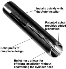
replacing worn valve guides
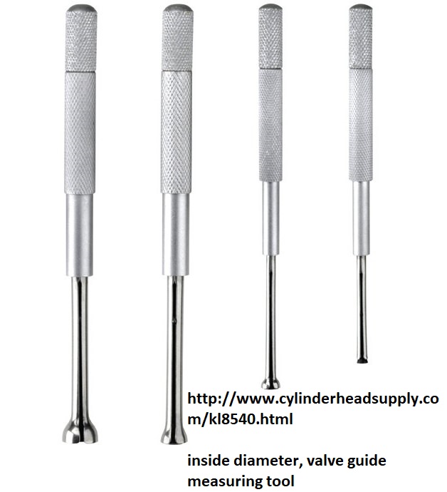
https://goodson.com/collections/cylinder-head-rebuilding-tools
http://www.cylinderheadsupply.com/kl8540.html
http://www.enginebuildermag.com/2003/12 ... ditioning/
http://www.calgaryfieros.com/OSGdocs/va ... seals.html
watch this video
http://www.hthoward.co.uk/engine-machin ... -sleeving/
http://www.hotrodlane.cc/New%20LS%20Lin ... inding.htm
Take the effort to read through ALL the related threads, with info you might need, as it will without any doubt be time very well spent and save you hours of wasted effort and a couple wheel-barrows full of cash over time!
http://www.cylinderheadsupply.com/valve-guide-tools-guide-top-cutters.html
When you drop off heads to be machined, its MANDATORY you are very clear and specific about what you want done,
and establish both the expected total cost and parts finished date or,
delivery time frame with the machine shop before work is started.
failure to do both almost always results in mis-understandings,
lower quality work, missed machine work being done, or a total failure of the machinist do do what you intended.
you can't for example say, "DO A VALVE JOB"
you need to be specific, saying I want a 3 angle or 5 angle valve job , what the angles are, what you want in valve mads, if they are too add new valve seats if required , test and replace all the valve springs, set the installed valve spring height at lets say 1.78" and a valve spring seat pressure falls in the expected range of of 180-193 lbs install new valve seals, verify the valve guide clearance back cut angle on the valve etc.
YES THIS WILL ALWAYS COST YOU MORE THAN A TYPICAL HIT OR MISS ONE ANGLE VALVE JOB< IT IT WILL GENERALLY RESULT IN A MUCH HIGHER QUALITY WORK AND MORE ATTENTION TO THE DETAILS
include diagrams and written instructions where needed
valve seat angles and air flow
valve seat angles and the actual angles cut on the valve edges them selfs and how you have the area under the valve in the port bowl area cut and blended has a marked effect on your engines air flow. as a general rule air flowing over a change in angle across a surface tends to become noticeable...garage.grumpysperformance.com
as a general rule air flowing over a change in angle across a surface tends to become noticeable more turbulent, if the change in angle exceeds about 15 degrees, and that tends to reduce flow. so if you look closely you see a tendency to cut the seat on a port in 15 degree steps or less.
I know from multiple experiences, that a throat and bowl clean up, mild combustion chamber contour smoothing, and a well done multi angle valve job, and upgrading to the correct valves and valve springs can very easily allow well over 1000 higher rpm and 30 plus extra horse power on a BBC.
when I first started building engines it was rather common for guys to drop heads off at the local machine shop and have the heads rebuilt and a valve job done, this consisted in most case in getting a 3 angle valve seat cut and a two angle cut on the valves and checking the guides and seals for wear and replacing them if it was required.
but after a few years of reading and doing some research I found I got much better results driving over a 120 miles to a PERFORMANCE machine shop that charged about twice as much for a valve job, but they cut three angles on the valves and 5 angles on the seats and cleaned and blended the bowl area under the valves, it was not unusual to see a car run one or two tenths faster in the 1/4 mile once that was done, compared to the stock, as cast factory heads, on a muscle car.
ccing the heads is always a good idea as is smoothing the combustion chamber and removing casting irregularities,
cc your cylinder heads, combustion chamber, or piston dome , or port volume
CC'ing a cylinder head is a process that measures the volume of the combustion chambers in the cylinder head. The term CC'ing is referring too the cubic centimeters of the pocket (combustion chamber). the purpose of cc'ing the head is to determine the size of the combustion chambers so they can...
garage.grumpysperformance.com
the change in power was usually noticeable.
keep in mind the valve starts flowing at least some airflow as the valve lifts off the seat but generally not a significant amount until the valves at least .006 off the seat and by .050 lift its generally flowing enough to measure easily, but keep in mind that even at only 1000rpm those valves are going thru repetitive cycles from fully seated to fully open and back to fully seated 8.3 times PER SECOND , and at 7000 rpm its 58 times PER second, so the time a valve remains at any specific lift is very minimal
in fact a simple change like a 30 degree back cut on a set of big block valves is usually worth an additional 10-15 hp, at very minimal cost and double angle back cuts have occasionally shown a bit more, flow especially at lower valve lifts.
Remember the valve is at minimal valve lift twice in each cycle while its only at peak lift once.
the port area under the valve seat must be smoothed and blended into the seat area to maximize air flow , but you generally don,t want the seat throat to exceed about 88%-90% of the valve diameter, or both flow and valve heat transfer to the valve seat is compromised.
we also learned that there were valves with longer valve stems and smaller diameter and lighter weight valves stems that would allow taller spring installed heights and larger springs for improved clearances, if you were willing to use custom length push rods and verify your valve train clearances and geometry, etc.
head gaskets are rarely completely round, nore are combustion chambers
you,ll want to place a head gasket you,ll use on the heads and mark the area inside the opening as the only areas you can change,
(notice the gasket fire ring is NOT a perfect circle like many people assume)
ideally you,ll want to un-shroud the valves while opening up the combustion chamber volume, but not extend the combustion chamber past the front edge of the gasket fire ring as that usually causes gasket failure
http://garage.grumpysperformance.com/index.php?threads/ccing-my-heads.14187/
http://garage.grumpysperformance.com/index.php?threads/iron-vs-aluminum-heads.389/#post-31684
http://garage.grumpysperformance.com/index.php?threads/multi-angle-valve-job-related.3143/#post-8387
http://garage.grumpysperformance.com/index.php?threads/port-speeds-and-area.333/
http://garage.grumpysperformance.co...r-piston-dome-or-port-volume.2077/#post-60554
PORT MATCHING THE INTAKE RUNNER EXIT TO THE CYLINDER HEAD PORT ENTRANCE USUALLY HELPS REDUCE RESTRICTIONS TO FLOW RATES, AND REDUCES FUEL/AIR DISTRIBUTION ISSUES
http://garage.grumpysperformance.com/index.php?threads/how-to-lap-valve-seats.1159/#post-2362
http://www.alexsparts.com/
http://www.summitracing.com/parts/man-11730-8
http://www.summitracing.com/parts/mil-45135-8
http://www.summitracing.com/parts/mil-45117-1
http://www.summitracing.com/parts/man-11847-8
ideally your port cross sectional area doesn,t change suddenly
valve seat and back face angles ,valve diameter and valve lift and duration effect the flow thru the curtain area
it should be rather obvious that youll need to know the exact distance the piston deck sits at TDC ,above or below the block deck surface and the valve notch recess or pop-up dome volume of the piston to do accurate quench or compression calculations
valve seat and back face angles ,valve diameter and valve lift and duration effect the flow thru the curtain area
keep in mind that valve may be forced off its seat, too full lift and re-seating 50 plus TIMES A SECOND at near 5500 rpm, so theres very little TIME for gases to move through the very restrictive space between the valve seat and valve edge
Calculating the valve curtain area
The following equation mathematically defines the available flow area for any given valve diameter and lift value:
Area = valve diameter x 0.98 x 3.14 x valve lift
Where 3.14 = pi (π)
For a typical 2.02-inch intake valve at .500-inch lift, it calculates as follows:
Area = 2.02 x 0.98 x 3.14 x 0.500 = 3.107 square inches
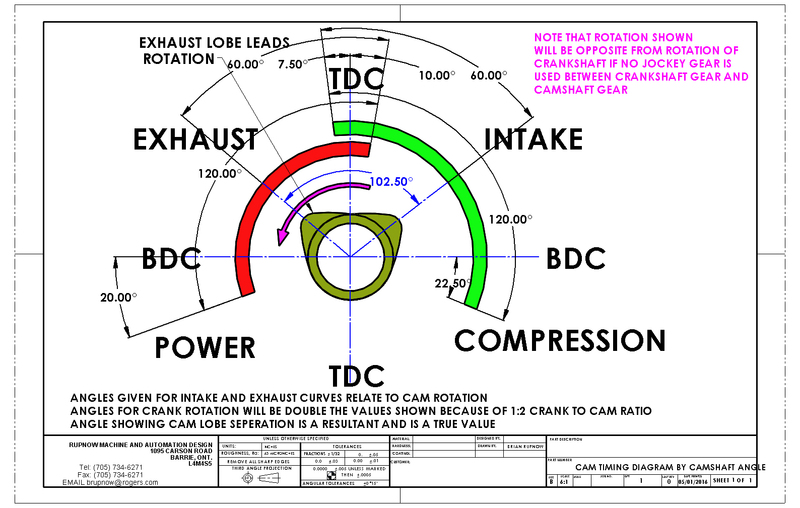
wider LSA smooths out the idle but it reduces overlap, the increased overlap tends to allow cylinder fill at a bit higher rpm and it also tends to kill off a bit of low rpm torque
keep in mind a cam simply controls PART of the complex sequence of mechanical , inertial flow,and thermal events that effect the engines cylinder filling exhaust scavenging efficiency , the head flow, intake design, efi or carb manifold, plenum and runners, exhaust header design, primairy and collector size and length, exhaust back pressure the fuel air ratio, the ignition timing, and the drive train gearing, the engine displacement, combustion chamber shape valve sizes, the valve seat angles and several other factors have significant effect on the power your likely to see and at what rpm, its available.
The following tables illustrate how variations in lobe separation angle and cam
timing will effect the behavior of the engine in which the camshaft is installed.
EFFECTS OF ALTERING CAMSHAFT TIMING
Advancing.......................................... Retarding
Begins Intake Event Sooner................. Delays Intake Closing Event
Open Intake Valve Sooner ........................Keeps Intake Valve Open Later
Builds More Low-End Torque................. Builds More High-RPM Power
Decrease Piston-Intake Valve Clearance Increase Piston-Intake Valve Clearance
Increase Piston-Exhaust Valve Clearance Decrease Piston-Exhaust Valve Clearance
keep in mind any valve clearance recessed areas must have the areas shrouding flow blended to increase rather than restrict air flow and to reduce the potential for detonation that sharp exposed edges tend to have
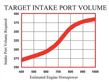
PROJECTED HP PORT VOL.
MIN - MAX MIN - MAX
350 - 400 140 -160
400 - 450 160 - 180
450 - 500 180 - 200
500 - 550 200 - 220
550 - 600 220 - 230
600 - 700 230 +
This chart gives a good working guideline as to the intake port volumes to target for a small-block Chevy. Remember, a little too small is much better than a little too big. If the port volume of the heads you have seems a little too big, go for all the compression ratio the fuel intended will stand, as this will, to some extent, compensate.
READ THRU THIS LINK
http://www.circletrack.com/enginetech/1 ... ch_engine/
http://garage.grumpysperformance.com/index.php?threads/how-to-lap-valve-seats.1159/#post-2362
USE THE CALCULATORS to match port size to intended rpm levels... but keep in mind valve lift and port flow limitations[/color]
http://www.wallaceracing.com/runnertorquecalc.php
http://www.wallaceracing.com/ca-calc.php
http://www.wallaceracing.com/area-under-curve.php
http://www.wallaceracing.com/chokepoint.php
http://www.wallaceracing.com/header_length.php
Most of the machinists prefer an intake-seat width of 0.040-0.060 inch. Narrower seats generally improve flow but are also less durable. Narrow seats work best on drag-race applications where the engine is freshened often. Harder seat materials (e.g., induction-hardened seats) allow you to run slightly narrower seat widths than in the past while retaining excellent durability. Since exhaust valves operate at extreme temperatures, they require a wider seat to conduct heat away from the valve through the seat. Most shops specify 0.060- to 0.080-inch seat width for the exhaust side.
http://www.chevyhiperformance.com/techa ... z2bm45kKdb
http://www.stockcarracing.com/techartic ... to_04.html
http://garage.grumpysperformance.co...olishing-combustion-chambers.2630/#post-50247
http://worldtracker.org/media/library/C ... pter23.pdf
as a general rule you'll find single plane intakes on a SBC generally work best on engine combos with at least a 245 duration cam at .050 lift and with 10.7:1 or higher compression and solid lifter cams that can operate efficiently in the 5500rpm-7000rpm PLUS power band and geared to operate in that same 5500rpm-7000rpm PLUS power band most of the time.
this also requires a short block assembly designed to operate in that upper rpm band, now as the engine displacement is increased, like in the larger displacement BBC engines port and runner air flow speeds will also increase so the effect is that a larger BBC engine can use more, or longer cam duration at a given rpm band, due to its larger cylinder volume to valve curtain area requiring more time, for effective cylinder fill and scavenging .
sellecting cylinder heads
you might want to watch this, its comparing the vortec SBC heads vs a CNC aluminum 210cc SBC head on a 383 (yes a head that large actually works and has a great deal more low and mid rpm torque that you may have been lead to believe, with 210cc ports and yes there are better heads in the...
garage.grumpysperformance.com
thus a 2.02 valve sbc reaches max flow near .505 lift
thus a 2.19 valve BBC reaches max flow near .5475 lift
Calculating the valve curtain area
The following equation mathematically defines the available flow area for any given valve diameter and lift value:
Area = valve diameter x 0.98 x 3.14 x valve lift
Where 3.14 = pi (π)
For a typical 2.02-inch intake valve at .500-inch lift, it calculates as follows:
Area = 2.02 x 0.98 x 3.14 x 0.500 = 3.107 square inches
For a typical 2.19-inch intake valve at .550-inch lift, it calculates as follows:
Area = 2.19 x 0.98 x 3.14 x 0.550 = 3.714 square inches
a typical 383 sbc with that .500 lift cam, has 47.875 cubic inches of volume in a single cylinder, divide that by the curtain area of 3.107 and you get 15 cubic inches of cylinder volume for each square inch of valve curtain
a typical 496 BBC with that .550 lift cam, has 62 cubic inches of volume in a single cylinder, divide that by the curtain area of 3.714 and you get 16.69 cubic inches of cylinder volume for each square inch of valve curtain, or about 11% less available air flow even with the larger valve and higher lift cam, to compensate use of a tighter LCA is frequently used to allow a longer, and more effective cylinder scavenging time frame in the big block combo
http://garage.grumpysperformance.com/index.php?threads/port-speeds-and-area.333/
http://garage.grumpysperformance.co...alves-and-polishing-combustion-chambers.2630/
http://garage.grumpysperformance.co...lsa-effects-your-compression-torque-dcr.1070/
THERES A GREAT DEAL MORE INFO IN THE LINKS AND SUB LINKS AS USUAL
http://zhome.com/ZCMnL/PICS/detonation/detonation.html
http://rlengines.com/Web_Pages/Serid_10 ... chine.html
http://www.superchevy.com/how-to/engine ... w-testing/
http://www.superchevy.com/how-to/engine ... omparison/
http://www.reidsautomotive.com/Cylinder ... vices.html
http://www.strokerengine.com/SBCHeadsFlow.html
http://www.chevyhiperformance.com/techa ... ve_angles/
http://www.popularhotrodding.com/tech/0 ... to_06.html
http://www.enginebuildermag.com/Article ... gines.aspx
http://www.enginebuildermag.com/Article ... pdate.aspx
http://www.aera.org/engine-professional ... echnology/
http://www.precisionenginetech.com/tech ... ns-part-2/
http://www.carcraft.com/techarticles/11 ... lve_angle/
http://www.allpar.com/fix/holler/valve-prepping.html
http://www.enginebuildermag.com/Article ... _jobs.aspx
http://www.chevyhiperformance.com/techa ... ewall.html
http://www.popularhotrodding.com/tech/1 ... ewall.html
http://www.carcraft.com/techarticles/11 ... ewall.html
http://www.enginebuildermag.com/Article ... _flow.aspx
By Larry Carley
Page 1 of 2
Next Page >>
Larry Carley
No one knows airflow better than the legendary Joe Mondello, who rose to fame back in the 1960s for his race-winning cylinder head work.
“Back in those days, we didn’t have flow benches to test our work. Our test bench was the drag strip. If a modification worked and made the car run faster, that’s what we used. If it didn’t work and the car ran slower, we went back to Plan A or tried something else.”
Today, it’s an entirely different situation. Mondello’s tech center in Crossville, TN, uses state-of-the art equipment to test and verify cylinder head modifications. Mondello says most of the development work he does today involves using a wet flow bench, a machine that mixes an ultraviolet dyed liquid mist with air to simulate what actually happens to the air/fuel mixture as it flows into the combustion chamber.
A dry flow bench measures airflow in cubic feet per minute (cfm), which is useful information for evaluating how changes that are made in the configuration of a port or the angles on a valve seat affect airflow at various valve lifts. But a wet flow bench shows you how those changes affect turbulence in the air/fuel mixture, and where fuel may be separating or puddling in the valve bowl, seat area and combustion chamber.
In other words, a wet flow bench shows you things you can’t see with a dry flow bench. It also allows you to verify the effect any modifications you’ve made are having on the air/fuel mixture that might hurt performance because of turbulence, fuel separation or puddling in the combustion chamber. The basic idea is to make sure the air/fuel mixture stays mixed and disperses evenly as it enters the combustion chamber so it will burn properly and produce maximum power.
“It’s important to remember that the engine is the primary guide for what kind of modifications actually produce more power, not just airflow numbers alone,” says Mondello. “That’s where the wet flow bench has really helped. The results we see on a wet flow bench are confirmed on the dyno and on the track. We can tear down an engine and look at the patterns on the pistons to confirm what the wet flow bench already told us.”
How Seat Angles Affect Airflow
Generally speaking, the more angles there are on the seats, the better the seat flows. A stock valve seat with only a single 45 degree angle cut on it will have a sharp edge just above and below the area where the valve sits on the seat. As the valve starts to open and air begins to flow past the valve, the abrupt change in angles create turbulence that reduces air velocity and flow.
This abrupt angle can also cause the air/fuel mixture to separate. So cutting another angle above the primary seat and a third angle below the seat helps smooth out the airflow. That’s why a traditional 30-45-60 degree three-angle valve job produces more power than a stock valve job. The extra angles help the air turn the corner so-to-speak, which reduces turbulence to improve air velocity and flow. It also lessens air/fuel separation to improve combustion, too.
Mondello says the traditional three-angle valve job is old hat in today’s performance engines. A 30-45-60 degree three angle valve job is still better than a single 45 degree cut on the valve seats, but it can’t come close to what’s possible by optimizing the valve seat profile with additional angles.
“A few weeks ago, we had three engineers from Harley-Davidson Screaming Eagle Division here for a technical session. They just designed a new 103 head and a 110 head and were quite proud of how well it flowed. We took their head, and in three days time we improved the airflow 52 cfm over their initial design. Out of the 53 cfm that we picked up, 25 cfm was due to changes we made in the valve seat angles alone. That shows you how critical valve seat angles are for maximizing airflow and power,” says Mondello.
“Many cylinder head manufacturers are using single point cutters on a CNC machine to cut their valve seats, and they are not spending much time blending the chambers or doing all the things they really should be doing to make the valve job work properly. That’s actually good for our business because we rework a lot of these cylinder heads, especially Harley heads,” Mondello explains.
The most important part of building any performance cylinder head is cutting the angles on the seats, Mondello says. “Over the years, many engine builders have relied on the basic 30-45-60 degree three angle cutter. They think they can use the same three seat angles on every cylinder head they do – but that’s not true. The angles that work best will vary depending on the application.”
Mondel says he prefers to use a fairly steep top angle, because a steeper angle improves airflow. “When the valve first opens, a steeper angle allows better flow into a combustion chamber that has hills and valleys and is not perfectly flat. If you have a 30 degree top angle, the air coming off that seat will be turbulent and you’ll get separation between the air and fuel which hurts power. Increasing the angle allows for a better transition from the seat into the combustion chamber. It’s more efficient, offers less resistance and makes more power.”
Mondello recalls that in his early days of reworking cylinder heads, he discovered that four angles often provided the best airflow, throttle response and power. The four angles he used were 45 degrees for the primary seat, a 33 to 37 degree top cut, a 58 degree undercut below the primary seat, and a 70 degree cut below that made with a hand-driven reamer. Using these angles can often improve airflow 8 to 15 cfm or more.
Finding the angles that work best with a given cylinder head, camshaft and valve combination requires a lot of time on both a wet and dry flow bench, as well as dyno testing and track time. A lot of small shops don’t have a flow bench or a dyno to do development work and testing on their engines. They have to rely on experience and feedback from their customers to determine what works on the track or drag strip. Consequently, they may not be getting as much power out of their engines as they could.
Special Valve Seat Cutters
To address this issue, Mondello has put his nearly 50 years of experience in reworking performance cylinder heads into his own line of high performance valve seat cutters. The “Joe Mondello Signature Series Infinite Flow Valve Seat Cutters” feature all of Mondello’s tricks for improving airflow, velocity and power. The valve seat cutters feature multiple valve angles that are proven to significantly improve airflow and power over a single angle or three-angle valve seat cutter. Mondello says his multi-angle cutters typically increase airflow 10 to 20 cfm by just adding and changing the angles on the valve seats.
However, Mondello urges caution and care when using a cutter that is designed for a certain application. “My exhaust seat cutters go from a primary seat into a full radius below that seat, but they’re only recommended for exhaust seats, not intake seats. A lot of guys will also use them to cut the intake valve seat because it shows an 8 to 10 cfm increase in airflow on a flow bench. But when you look at the actual airflow pattern on a wet flow bench, the profile that was developed for the exhaust seat causes bad fuel shear and turbulence in the valve bowl and seat area. That’s why I offer different profiles for the intake seats.”
Of course, putting a radius on the intake seat is nothing new, and a lot of guys have been doing it for years because it increases airflow. But Mondello says bigger airflow numbers don’t necessarily translate into more power. It depends on what happens to the air/fuel mixture as it enters the combustion chamber.
“My valve seat cutters are designed to improve airflow, throttle response and horsepower, and they can be used on heads for street cars as well as a race car. Either way, you’re going to get better results than a simple three-angle valve job,” he says.
Mondello says that when cutting a full radius on exhaust seats, it is better to use a seat with a straight ID rather than a seat with a taper ID. With the straight ID, you can form the full radius up to the primary seat without having to worry about running into the bottom taper or leaving a ridge at the bottom of the seat. “I use an 86 degree radius undercut blade (IFT 86R6B-HP) to cut the very bottom of the seat and to clean out that little ring or any deformation that might be left from the seat cutter.”
Mondello’s product line includes a new exhaust seat cutter for heads with smaller valves like those from BMW and Audi, and will soon add a cutter for the intake seats. He also has cutters specially-designed for Harley intake and exhaust valve seats.
Besides making more power, cutting additional angles on the valve seats allows a shop to charge more for a valve job. “It’s a value-added service that improves performance, so why not charge more for it?” asks Mondello.
Important Ratios
Another factor that has a huge impact on airflow through the valve port and seat is the ratio of the size of the valve opening to the size of the throat area just below the base of the valve seat (as measured from the largest area at the bottom of the valve seat). The number one rule here, says Mondello, is having the optimum ratio that maximizes air velocity through the “primary choke” area in the valve bowl just under the seat.
“A lot of the aftermarket performance heads today are typically made with a 91 to 92 percent throat area, which, in my opinion, is too big,” says Mondello. “To get maximum velocity and airflow, the ratio needs to be a little smaller. On many heads, a throat dimension-to-valve size percentage of 86-1/2 to 89 flows best. On Harley motorcycle heads, we use 89 percent. On big displacement high flow V8 racing heads with valve sizes from 2.100˝ to 2.25˝, we may go as high as 90 to 91 percent. We try to keep the choke area as small as we can so it will flow efficiently and improve velocity in the port runner.”
He explains, “If you have big ports in a cylinder head but only a so-so valve seat, the head won’t flow as well as it could. Engines run on velocity, not cfm airflow numbers. The right valve angles will have a supercharging effect that really helps ram more air and fuel into the cylinder. That’s what gives you instant throttle response instead of a bog when you stomp down on the gas pedal.”
Mondello says a bowl cutter should be used to achieve the proper percentage for the valve-to-throat dimension size. Even if a performance engine has to run under a “no porting” rule, the bowl area under the seat can be cleaned up to improve airflow. Reworking this area can often improve airflow an additional 8 to 14 cfm.
Is Good Quality Valve Work Possible With Outdated Equipment?
Mondello chastises shops that are still using old, worn-out equipment to do what they call “performance” valve jobs. “It isn’t really performance work if the equipment can’t hold tight tolerances,” he says. “A tolerance of a couple thousandths of an inch is not close enough when performance valve work requires holding tolerances to tenths of a thousandth. The valve-and-seat machine bearings and pilots have to be in good condition.”
The concentricity of the valve seats to the valve guides is critical not only for proper valve seating and sealing, but also for the longevity of the valves. Misalignment between the valves and seats forces the valve stem to flex every time the valve seats. Eventually, this can lead to metal fatigue and valve failure. So the seats have to be as concentric to the guides as possible.
Mondello said the valve guide pilots that some shops use have too much play for accurate valve work. A valve-to-guide tolerance of .0004˝ is too much for performance work. It should be down around .0002˝ or less. One way to achieve that is to use a high-pressure lubricant on the pilot. Mondello prefers a lubricant called CMD-3, which can handle up to 50,000 psi. The same lubricant can also be used on a dead pilot to take slop out of the valve cutting system.
Chatter is another problem that can ruin a performance valve job. Chatter can be caused by three things: too much play in the pilot (or to the guide if the valve-and-seat machine uses a live pilot versus a dead pilot) or the speed of the cutter. However another culprit may be the casue and have nothing to do with the pilot or the cutter: examine how level your machine actually is compared to what you think it is.
“If your valve-and-seat machine is off-kilter just a bit, the valve seat cutter can chatter when it cuts the seat,” Mondello explains. “When was the last time you leveled your machine? More importantly, when was the last time you leveled your level?”
The Living Legend continues: “Many people don’t know that a level is not flat on the bottom. It has a bow in it. Most people also don’t know how to check their level. You can’t accurately level your valve-and-seat machine if the level you are using is off. When you set your level, make sure the little level is always to your left. If you turn it around, you will get a different reading.”
Mondello says using a lubricant when cutting hard seats will also reduce chatter. He uses a 2020 Mondello Signature Series cutting fluid for this purpose, and 2030 Mondello Signature Series fluidwhen refacing titanium and stainless steel valves.
Seat Materials
The type of seat material used will depend on the application. Racers running titanium valves typically use a beryllium-copper alloy seat, or one of the new beryllium-free copper-nickel alloys. Beryllium-copper and copper-nickel seats have a high rate of thermal conductivity, and are a must for high revving, high power engines with titanium valves.
Mondello says one of his favorite materials for valve seats is powder metal. He says he uses powder metal seats from a leading U.S. manufacturer in many of the heads he rebuilds. He likes the powder metal seats for a variety of reasons: they have great machinability when they are new, they produce very little chatter when you cut them, they have built-in lubricity for the valves, they hold up well, and they are made in the USA.
Mondello urges engine builders to be very vigilant about their suppliers, because in his opinion, not all manufacturers pay close enough attention to their alloys. Consequently, the hardness of the seats may vary greatly even within the same size seat.
Interference Fit
Keeping the seats in is just as important as the angles that are cut on the seats. Mondello says one of the most common problems he sees are engine builders not using the proper press fit when they install valve seats. “You should always preheat aluminum heads and freeze the seats prior to installing them (Mondello does not recommend preheating iron heads).
I recommend .005˝ to .0065˝ of interference when installing seats in a cast iron head, and .0065˝ to .007˝ in an aluminum head, unless the seats are Beryllium Copper, in which case I recommend .004˝ to .0045˝ of interference fit. Some guys tell me .007˝ to .0065˝ of interference in an aluminum head is too much. But you know what? I’ve never had a seat drop out, not even after an engine got too hot and overheated.”
Mondello says to achieve a good fit, you need a good hole (correct dimensions, smooth finish and no distortion or damage to the seat counterbore). You also have to use a lubricant when driving in the seat.
“I don’t believe in using locking compound on valve seats. It interferes with the heat transfer. All you need is a little assembly lube,” he says.
Mondello says shape is important too. “The valve seat should also have a chamfer on the bottom edge. If you’re finding your seats are straight cut with a flat bottom. You need to put a bevel on those seats before you install them. And regardless of what type of seat you are installing, always use a pilot and driver. Some guys will just beat the seats in using a driver and a puck. That’s asking for trouble. Use a pilot to align the seat so it goes in straight.”
Mondello cautions against using excessive heat when preheating a cylinder head to install new seats. “You only need to heat the head up to about 160 to 180 degrees F. If you get it too hot, say 200 to 250 degrees F, the guides can move around and change the alignment between the guide and seat. When we do Harley heads, we preheat the head on an electric stove. You can also use a hot plate or a torch for the same purpose.”
To be sure, Mondello urges precision. “Use an infrared thermometer to check the temperature. We put the seats in a freezer while the head is being warmed up. That makes it very easy to install the seats. You can almost drop them into place.”
Mondello says you have to install the valve guides before you do the seats. The position of the guides determines the position of the seats, so once the guides are in place, they can be used to pilot the position of the seats.
“On Harley heads, we drive the valve guides into the head from the top (from the spring seats). On most other V8 heads, we also drive the guides in from the top (spring seat side). On early 396/427 Chevys where the guide exhaust guide is stepped, you have to drive out the old exhaust guide from the combustion chamber. New intake and exhaust guides can then be driven in from the top side.”
related info, that you might need
http://garage.grumpysperformance.co...heads-for-small-block-chevys.3293/#post-26213
http://garage.grumpysperformance.com/index.php?threads/what-are-these-heads.4702/#post-12742
http://garage.grumpysperformance.co...-by-step-guide-with-pictures.5378/#post-71848
http://garage.grumpysperformance.co...ther-efi-intake-manifold-info.431/#post-26322
http://garage.grumpysperformance.com/index.php?threads/porting-can-help.462/page-3#post-59145
http://garage.grumpysperformance.co...ads-tuned-intake-turbulence.12998/#post-67611
CCs of Head Gasket = Bore x Bore x 12.87 x Thickness of Head Gasket
COMMON SBC INTAKE PORTS
felpro # 1204=Port Size: 1.23" x 1.99"=2.448 sq inches
felpro # 1205=Port Size: 1.28" x 2.09"=2.67 sq inches
felpro # 1206=Port Size: 1.34" x 2.21"=2.96 sq inches
felpro # 1207=Port Size: 1.38" x 2.28"=3.146 sq inches
felpro # 1209=Port Size: 1.38" x 2.38"=3.28 sq inches
felpro # 1255 VORTEC=Port Size: 1.08" x 2.16"-2.33 sq inches
felpro # 1263=Port Size: 1.31" x 2.02"=2.65 sq inches
felpro # 1266=Port Size: 1.34" x 2.21"=2.96 sq inches
felpro # 1284 LT1=Port Size: 1.25 x 2.04''=2.55 sq inches
felpro # 1289 FASTBURN=Port Size: 1.30" x 2.31" 3.00 sq inches
http://users.erols.com/srweiss/calccsa.htm
Your RPM computed from your Cross Sectional Area of 1.95
(the smaller AFR HEADS)
and Bore of 4.03 and Stroke of 3.75 is 5,569.12 .
Your RPM computed from your Cross Sectional Area of 2.05
(the Larger AFR HEADS)
and Bore of 4.03 and Stroke of 3.75 is 5,854.72 .
you,ll barely notice the about 300 rpm shift in the power band on the lower part of rpm range but appreciate it much more on the upper edge of that power curve
heres a chart FROM THE BOOK,HOW TO BUILD BIG-INCH CHEVY SMALL BLOCKS with some common cross sectional port sizes
(measured at the smallest part of the ports)
...........................sq inches........port cc
edelbrock performer rpm ....1.43.............170
vortec......................1.66.............170
tfs195......................1.93.............195
afr 180.....................1.93.............180
afr 195.....................1.98.............195
afr 210.....................2.05.............210
dart pro 200................2.06.............200
dart pro 215................2.14.............215
brodix track 1 .............2.30.............221
dart pro 1 230..............2.40.............230
edelbrock 23 high port .....2.53.............238
edelbrock 18 deg............2.71.............266
tfs 18 deg..................2.80.............250
USE THE CALCULATORS
http://www.rbracing-rsr.com/runnertorquecalc.html
http://www.wallaceracing.com/chokepoint.php
http://www.wallaceracing.com/header_length.php
http://www.superchevy.com/how-to/en...-0902-chevy-engine-port-variations-measuring/
http://www.hotrod.com/articles/choosing-the-right-camshaft/
http://garage.grumpysperformance.com/index.php?threads/bits-of-383-info.38/
Last edited: 1 minute ago
The key to performance valve work, therefore, is knowing the angles, having a valve-and-seat machine that’s in good condition and can maintain tight tolerances, and paying attention to details.
replacing worn valve guides
https://goodson.com/collections/cylinder-head-rebuilding-tools
http://www.cylinderheadsupply.com/kl8540.html
http://www.enginebuildermag.com/2003/12 ... ditioning/
http://www.calgaryfieros.com/OSGdocs/va ... seals.html
http://www.hthoward.co.uk/engine-machin ... -sleeving/
http://www.hotrodlane.cc/New%20LS%20Lin ... inding.htm
Take the effort to read through ALL the related threads, with info you might need, as it will without any doubt be time very well spent and save you hours of wasted effort and a couple wheel-barrows full of cash over time!
http://www.cylinderheadsupply.com/valve-guide-tools-guide-top-cutters.html
Last edited by a moderator: