USE THE CALCULATORS
http://www.rbracing-rsr.com/runnertorquecalc.html
http://www.wallaceracing.com/chokepoint.php
http://www.wallaceracing.com/header_length.php
http://www.wallaceracing.com/chokepoint.php
http://www.rbracing-rsr.com/runnertorquecalc.html
http://www.velocity-of-sound.com/velocity_of_sound/calculator1.htm
http://garage.grumpysperformance.co...alves-and-polishing-combustion-chambers.2630/
Calculating the valve curtain area
The following equation mathematically defines the available flow area for any given valve diameter and lift value:
Area = valve diameter x 0.98 x 3.14 x valve lift
Where 3.14 = pi (π)
For a typical 2.02-inch intake valve at .500-inch lift, it calculates as follows:
Area = 2.02 x 0.98 x 3.14 x 0.500 = 3.107 square inches
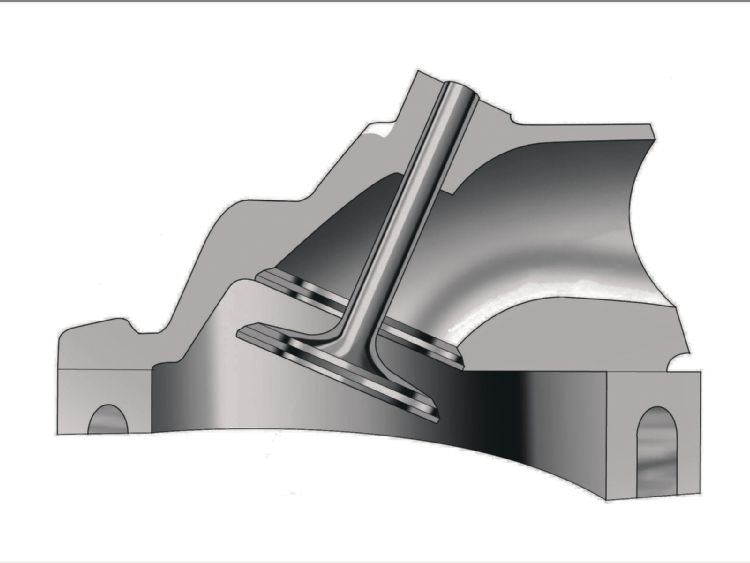
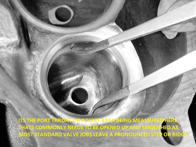
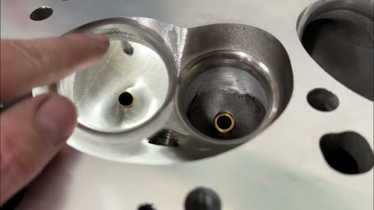
a basic but effective valve job with blended port bowl area clean -up helps flow rates
Unless rotary valves are perfected, poppet valves will continue to be the crucial moving airflow component in today’s high-performance engines. Their shape, material selection and preparation can make or break an engine’s ultimate performance, regardless of the development of high-profile parts like cylinder heads and induction systems.
“Engine valves exert enormous influence on engine airflow, mixture quality and the ability to run higher engine speeds,” says Zeke Urrutia of Ferrea Racing Components, which manufacturers of high-performance racing valves and valvetrain components.
The valves must provide a perfect seal at all engine speeds, and their size, shape and seat angles must support the best possible mixture movement through the flow window. Specific materials are also required to maintain durability in the harsh combustion environment, but valve weight is also a paramount consideration to ensure effective high speed operation. In essence, there is much more to the ordinary engine valve than fundamentally meets the eye.
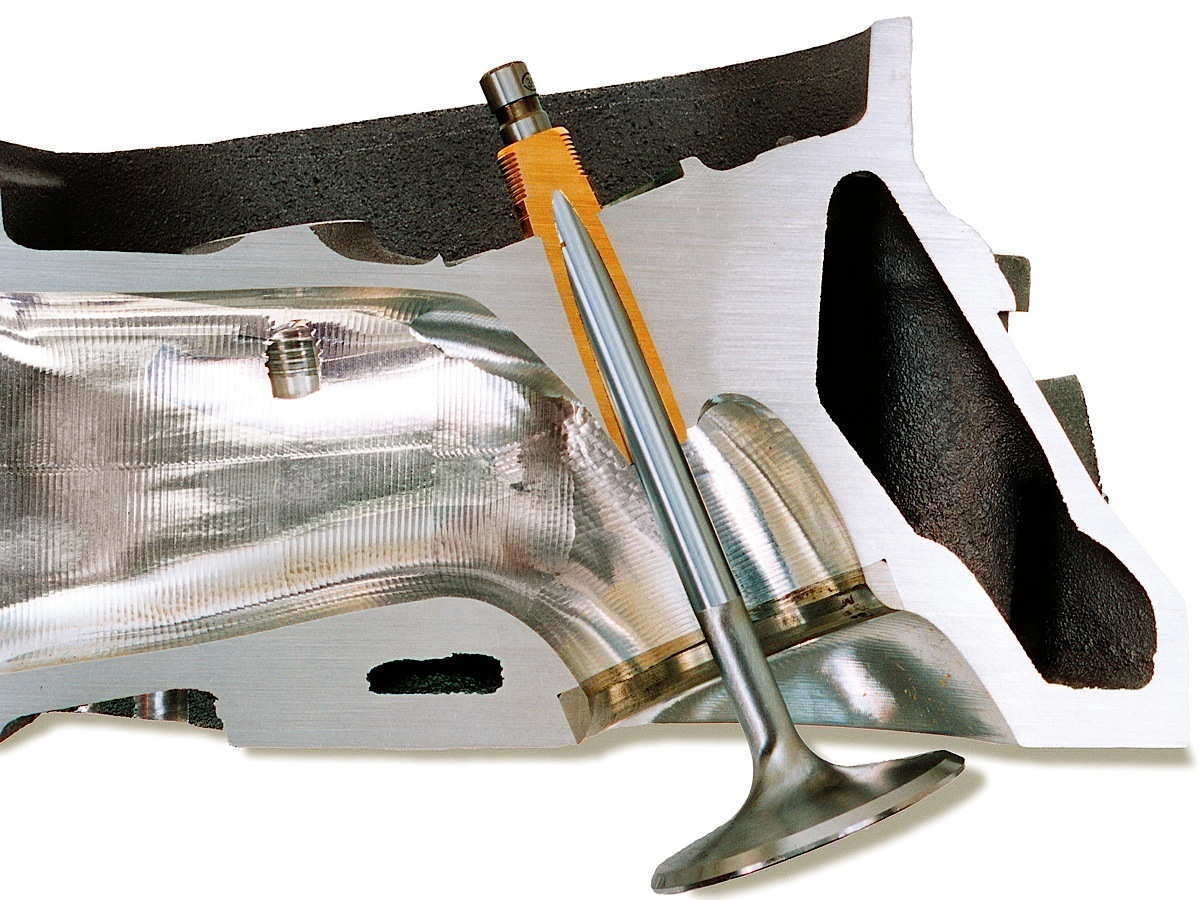
While the broad science of engine airflow is surprisingly complex, this report will focus on the basic content and function of engine valves and how they contribute to engine performance. The conventional valve and valve-seat configuration has proved to be the most practical way of feeding an engine. Unfortunately, this partnership is also the single greatest restriction to engine airflow. While port shape, length and cross section are the primary considerations of engine airflow dynamics, the throat area just above the valve is the most restrictive and the most crucial element of optimum airflow and mixture quality. In fact, the area approximately ½-inch above and below the intake valve is the most influential factor of the entire inlet flow path. Maintaining good airspeed past the rapidly opening and closing valves is the engine builder’s top priority.
Enhancing mixture quality
Multi-angle valve jobs are used to ease the flow transition from the port to the chamber on the intake side and from the chamber to the port on the exhaust side. The width, number and concentricity of these cuts influence sealing effectiveness and flow quality.
“A properly configured valve and valve seat angle can significantly improve air flow and enhance mixture quality at the same time,” stresses Urrutia.
Steady-state airflow past an open valve (on a flow bench) is one crucial measure, but starting and stopping that column of air (and fuel droplets) many times per second is not conducive to the smooth transfer of the fuel/air medium from the induction system. And it is certainly not supportive of good mixture quality when fuel droplets are violently slammed against the back of the valve at high speed and just as quickly accelerated and flushed past the seat into the cylinder where a whole different pressure environment exists.
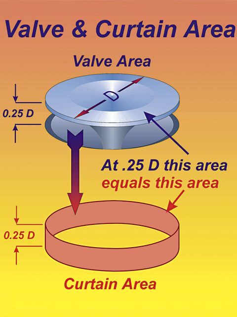
The valve is a simple variable-geometry device that controls the opening and closing of the specified flow window or valve curtain area as determined by the camshaft and rocker ratio. The valve curtain area is defined as the flow window created by the open valve at maximum valve lift. To calculate valve curtain area you can’t go by the valve diameter itself. You have to use the flow diameter, which is where the actual valve seat begins and that is generally about .040-inch smaller than the measured valve diameter. A generally accurate formula for the flow diameter is multiplying the valve diameter by 0.98 (see sidebar).
Calculating the valve curtain area
The following equation mathematically defines the available flow area for any given valve diameter and lift value:
Area = valve diameter x 0.98 x 3.14 x valve lift
Where 3.14 = pi (π)
For a typical 2.02-inch intake valve at .500-inch lift, it calculates as follows:
Area = 2.02 x 0.98 x 3.14 x 0.500 = 3.107 square inches
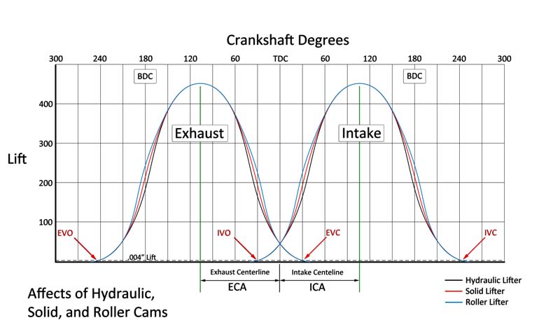
Maximum valve opening, rate of opening and length of time the valve is open are controlled by the camshaft, but the valve size, shape and seat angles have a profound effect on overall airflow efficiency.
If we accept that airspeed and net mass flow are the key components of cylinder filling, it’s easy to see that moving high-velocity air past the valve and into the combustion chamber smoothly with minimal turbulence is critical to optimizing performance. Engine builders refer to this as pressure recovery or the efficient slowing of high velocity air and transforming kinetic flow energy into cylinder pressure. In the runner and past the valve, air velocity is high and the static pressure is low. Inside the cylinder, pressure is higher and airspeed is reduced due to the dramatic change in area. A gradual transition from low static pressure and high velocity past the valve to higher static pressure and low velocity in the cylinder aids cylinder filling and makes the most efficient use of a properly designed port.
Equal airflow
“This depends greatly on the shape of the combustion chamber, but the real key is to get the airflow as equal as possible around the entire circumference of the valve,” explains Urrutia. “This is difficult to achieve because the port almost always approaches the valve from an oblique angle, and flow is kinetically biased to follow its own preferred direction — which rarely favors even flow around the valve.”
Flow dynamics are further complicated when the combustion chamber typically shrouds 30 or more percent of the valve. That’s why pocket porting and unshrouding the valve picks up power, but the valve shape and seat angles play a significant role in optimizing flow efficiency and mixture quality through effective fuel shearing across the seat.
Titanium valves offer multiple benefits, despite their higher initial cost. — Zeke Urrutia, Ferrea
The role of the valve is critical at all lift values, but a key proportion is the LD ratio — or the lift-to-diameter ratio — where the lift value equals one-quarter of the valve’s diameter. Regardless of valve diameter, at this point the valve curtain area is exactly equal to the valve head area.
“Everything below this strongly influences low-lift flow,” says Urrutia, “which is an important function of overcoming fuel-mixture inertia.”
Unless rotary valves are perfected, poppet valves will continue to be the crucial moving airflow component in today’s high-performance engines. Their shape, material selection and preparation can make or break an engine’s ultimate performance, regardless of the development of high-profile parts like cylinder heads and induction systems.
“Engine valves exert enormous influence on engine airflow, mixture quality and the ability to run higher engine speeds,” says Zeke Urrutia of Ferrea Racing Components, which manufacturers of high-performance racing valves and valvetrain components.
An open valve creates a flow window defined by the valve seat flow diameter and the amount of lift created by the camshaft. At most lift values a significant portion of the flow window is partially obstructed by the combustion chamber walls, making it difficult to obtain equal flow around the entire circumference of the valve.
The valves must provide a perfect seal at all engine speeds, and their size, shape and seat angles must support the best possible mixture movement through the flow window. Specific materials are also required to maintain durability in the harsh combustion environment, but valve weight is also a paramount consideration to ensure effective high speed operation. In essence, there is much more to the ordinary engine valve than fundamentally meets the eye.
While the broad science of engine airflow is surprisingly complex, this report will focus on the basic content and function of engine valves and how they contribute to engine performance. The conventional valve and valve-seat configuration has proved to be the most practical way of feeding an engine. Unfortunately, this partnership is also the single greatest restriction to engine airflow. While port shape, length and cross section are the primary considerations of engine airflow dynamics, the throat area just above the valve is the most restrictive and the most crucial element of optimum airflow and mixture quality. In fact, the area approximately ½-inch above and below the intake valve is the most influential factor of the entire inlet flow path. Maintaining good airspeed past the rapidly opening and closing valves is the engine builder’s top priority.
Enhancing mixture quality
Multi-angle valve jobs are used to ease the flow transition from the port to the chamber on the intake side and from the chamber to the port on the exhaust side. The width, number and concentricity of these cuts influence sealing effectiveness and flow quality.
“A properly configured valve and valve seat angle can significantly improve air flow and enhance mixture quality at the same time,” stresses Urrutia.
Steady-state airflow past an open valve (on a flow bench) is one crucial measure, but starting and stopping that column of air (and fuel droplets) many times per second is not conducive to the smooth transfer of the fuel/air medium from the induction system. And it is certainly not supportive of good mixture quality when fuel droplets are violently slammed against the back of the valve at high speed and just as quickly accelerated and flushed past the seat into the cylinder where a whole different pressure environment exists.
The valve is a simple variable-geometry device that controls the opening and closing of the specified flow window or valve curtain area as determined by the camshaft and rocker ratio. The valve curtain area is defined as the flow window created by the open valve at maximum valve lift. To calculate valve curtain area you can’t go by the valve diameter itself. You have to use the flow diameter, which is where the actual valve seat begins and that is generally about .040-inch smaller than the measured valve diameter. A generally accurate formula for the flow diameter is multiplying the valve diameter by 0.98 (see sidebar).
Calculating the valve curtain area
The following equation mathematically defines the available flow area for any given valve diameter and lift value:
Area = valve diameter x 0.98 x 3.14 x valve lift
Where 3.14 = pi (π)
For a typical 2.02-inch intake valve at .500-inch lift, it calculates as follows:
Area = 2.02 x 0.98 x 3.14 x 0.500 = 3.107 square inches
Maximum valve opening, rate of opening and length of time the valve is open are controlled by the camshaft, but the valve size, shape and seat angles have a profound effect on overall airflow efficiency.
If we accept that airspeed and net mass flow are the key components of cylinder filling, it’s easy to see that moving high-velocity air past the valve and into the combustion chamber smoothly with minimal turbulence is critical to optimizing performance. Engine builders refer to this as pressure recovery or the efficient slowing of high velocity air and transforming kinetic flow energy into cylinder pressure. In the runner and past the valve, air velocity is high and the static pressure is low. Inside the cylinder, pressure is higher and airspeed is reduced due to the dramatic change in area. A gradual transition from low static pressure and high velocity past the valve to higher static pressure and low velocity in the cylinder aids cylinder filling and makes the most efficient use of a properly designed port.
Equal airflow
“This depends greatly on the shape of the combustion chamber, but the real key is to get the airflow as equal as possible around the entire circumference of the valve,” explains Urrutia. “This is difficult to achieve because the port almost always approaches the valve from an oblique angle, and flow is kinetically biased to follow its own preferred direction — which rarely favors even flow around the valve.”
Valve angle relative to the cylinder bore influences flow characteristics. A raised port and shallower valve angle improves flow by providing a straighter flow path and reduced valve shrouding. In some cases a slightly smaller valve will perform better because it helps to overcome the effects of shrouding.
Flow dynamics are further complicated when the combustion chamber typically shrouds 30 or more percent of the valve. That’s why pocket porting and unshrouding the valve picks up power, but the valve shape and seat angles play a significant role in optimizing flow efficiency and mixture quality through effective fuel shearing across the seat.
Titanium valves offer multiple benefits, despite their higher initial cost. — Zeke Urrutia, Ferrea
The role of the valve is critical at all lift values, but a key proportion is the LD ratio — or the lift-to-diameter ratio — where the lift value equals one-quarter of the valve’s diameter. Regardless of valve diameter, at this point the valve curtain area is exactly equal to the valve head area.
“Everything below this strongly influences low-lift flow,” says Urrutia, “which is an important function of overcoming fuel-mixture inertia.”
The accompanying chart indicates standard valve lengths for popular performance engines. Important dimensions include overall valve length, head diameter, margin height and tip length.
Above this point, the engine builder needs to compare the minimum port cross-sectional area (typically the throat area above the valve) to the valve curtain area. Somewhere around the mid-lift point, the valve curtain area becomes larger than the port area and the port itself becomes the restriction. This is called the saturation lift point. At every point in this equation we are stuck with the same fixed valve shape, seat angles and valve margin dimensions that influence air movement. Above the saturation point, the seat angles are still crucial to maintaining smooth transitional flow and providing a shear edge to help maintain good fuel atomization. The particulars of this are very specific to any given combustion chamber, according to its size, shape, depth, valve position, port texture approaching the valve and, to some degree, the influence of the rising piston crown.
What’s the angle?
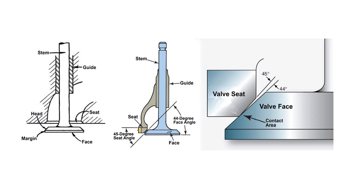
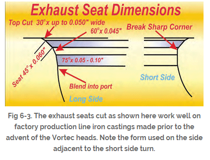
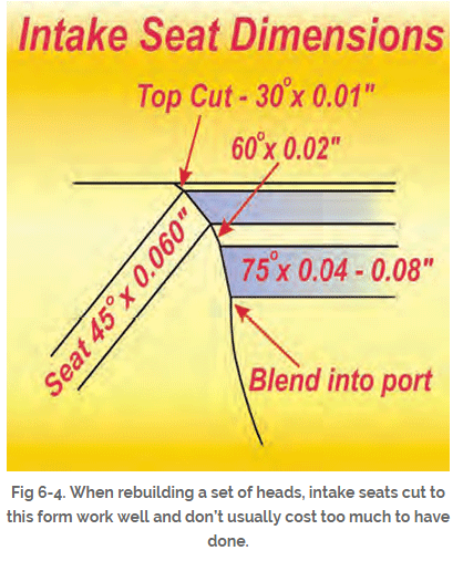
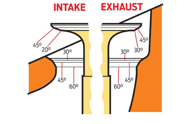
A standard 3-angle valve job typically begins with a 60-degree cut in the port throat area to establish a transition to the 45-degree sealing angle that contacts the valve. Above that, a top cut of 15 to 35 degrees typically completes the transition into the combustion chamber. Today many performance valve jobs incorporate up to five different angles, including in some cases a 70- to 75-degree throat cut, depending on the port and its flow characteristics. Generally, inlet flow or exhaust flow does not lose velocity or become turbulent as long as the valve seat or valve angle transitions do not exceed 15 degrees.
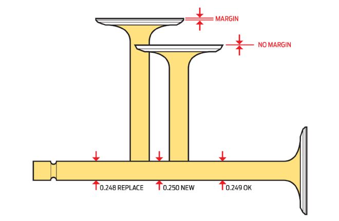
The standard seat angle on the valve is 45 degrees. Some applications like Pro Stock drag racing use up to a 55-degree angle on the valve and the seat. This has been found to increase flow, but it is less durable and it cannot be used in supercharged or turbocharged applications because it can’t take the higher temperatures. A 30-degree back cut on the valve helps ease the transition to the seat and a sharp corner on the bottom of the intake valve margin helps resist reversion flow by interrupting its passage back into the port. For most performance applications the intake valve margin height is typically .050-inch and intake valves typically require a tight radius from the stem to the head to prevent low lift restriction.
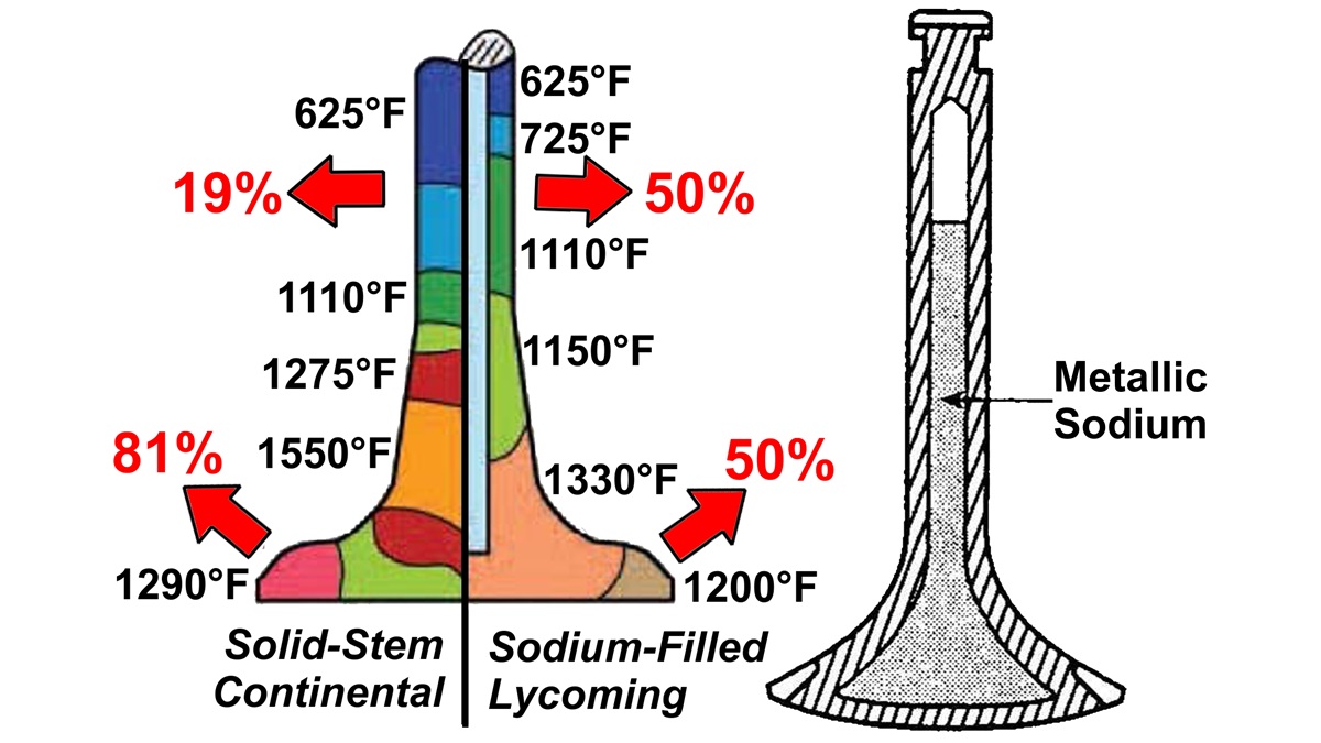
Exhaust valves generally require the same angles, but use a narrower seat to help the valve cut through carbon buildup and maintain a positive seal. Valve margin should be .080-.090-inch tall to provide durability under higher temperatures and it should have a radius at the bottom to encourage exhaust gas flow around the valve. A tulip shape is often used on exhaust valves to encourage smoother flow.
“This works well, compared to tight radius of intake valves because exhaust gases are still under pressure and can’t wait to get out,” says Urrutia. “Intake mixtures have little relative pressure and must be coaxed into the cylinder through port dynamics.”
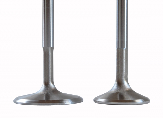
intake valve (left) has a 30° back cut above the seat and a thin margin with a sharp edge on the bottom to discourage inlet tract reversion. Corresponding exhaust valve has a thicker margin to resist higher temperatures and a generous radius on the bottom to encourage exit flow around the valve. Intake valves use a nail head configuration to avoid flow restriction.
http://www.rbracing-rsr.com/runnertorquecalc.html
http://www.wallaceracing.com/chokepoint.php
http://www.wallaceracing.com/header_length.php
http://www.wallaceracing.com/chokepoint.php
http://www.rbracing-rsr.com/runnertorquecalc.html
http://www.velocity-of-sound.com/velocity_of_sound/calculator1.htm


http://garage.grumpysperformance.co...alves-and-polishing-combustion-chambers.2630/
Calculating the valve curtain area
The following equation mathematically defines the available flow area for any given valve diameter and lift value:
Area = valve diameter x 0.98 x 3.14 x valve lift
Where 3.14 = pi (π)
For a typical 2.02-inch intake valve at .500-inch lift, it calculates as follows:
Area = 2.02 x 0.98 x 3.14 x 0.500 = 3.107 square inches


a basic but effective valve job with blended port bowl area clean -up helps flow rates


Unless rotary valves are perfected, poppet valves will continue to be the crucial moving airflow component in today’s high-performance engines. Their shape, material selection and preparation can make or break an engine’s ultimate performance, regardless of the development of high-profile parts like cylinder heads and induction systems.
“Engine valves exert enormous influence on engine airflow, mixture quality and the ability to run higher engine speeds,” says Zeke Urrutia of Ferrea Racing Components, which manufacturers of high-performance racing valves and valvetrain components.
The valves must provide a perfect seal at all engine speeds, and their size, shape and seat angles must support the best possible mixture movement through the flow window. Specific materials are also required to maintain durability in the harsh combustion environment, but valve weight is also a paramount consideration to ensure effective high speed operation. In essence, there is much more to the ordinary engine valve than fundamentally meets the eye.
While the broad science of engine airflow is surprisingly complex, this report will focus on the basic content and function of engine valves and how they contribute to engine performance. The conventional valve and valve-seat configuration has proved to be the most practical way of feeding an engine. Unfortunately, this partnership is also the single greatest restriction to engine airflow. While port shape, length and cross section are the primary considerations of engine airflow dynamics, the throat area just above the valve is the most restrictive and the most crucial element of optimum airflow and mixture quality. In fact, the area approximately ½-inch above and below the intake valve is the most influential factor of the entire inlet flow path. Maintaining good airspeed past the rapidly opening and closing valves is the engine builder’s top priority.
Enhancing mixture quality
Multi-angle valve jobs are used to ease the flow transition from the port to the chamber on the intake side and from the chamber to the port on the exhaust side. The width, number and concentricity of these cuts influence sealing effectiveness and flow quality.
“A properly configured valve and valve seat angle can significantly improve air flow and enhance mixture quality at the same time,” stresses Urrutia.
Steady-state airflow past an open valve (on a flow bench) is one crucial measure, but starting and stopping that column of air (and fuel droplets) many times per second is not conducive to the smooth transfer of the fuel/air medium from the induction system. And it is certainly not supportive of good mixture quality when fuel droplets are violently slammed against the back of the valve at high speed and just as quickly accelerated and flushed past the seat into the cylinder where a whole different pressure environment exists.
The valve is a simple variable-geometry device that controls the opening and closing of the specified flow window or valve curtain area as determined by the camshaft and rocker ratio. The valve curtain area is defined as the flow window created by the open valve at maximum valve lift. To calculate valve curtain area you can’t go by the valve diameter itself. You have to use the flow diameter, which is where the actual valve seat begins and that is generally about .040-inch smaller than the measured valve diameter. A generally accurate formula for the flow diameter is multiplying the valve diameter by 0.98 (see sidebar).
Calculating the valve curtain area
The following equation mathematically defines the available flow area for any given valve diameter and lift value:
Area = valve diameter x 0.98 x 3.14 x valve lift
Where 3.14 = pi (π)
For a typical 2.02-inch intake valve at .500-inch lift, it calculates as follows:
Area = 2.02 x 0.98 x 3.14 x 0.500 = 3.107 square inches
Maximum valve opening, rate of opening and length of time the valve is open are controlled by the camshaft, but the valve size, shape and seat angles have a profound effect on overall airflow efficiency.
If we accept that airspeed and net mass flow are the key components of cylinder filling, it’s easy to see that moving high-velocity air past the valve and into the combustion chamber smoothly with minimal turbulence is critical to optimizing performance. Engine builders refer to this as pressure recovery or the efficient slowing of high velocity air and transforming kinetic flow energy into cylinder pressure. In the runner and past the valve, air velocity is high and the static pressure is low. Inside the cylinder, pressure is higher and airspeed is reduced due to the dramatic change in area. A gradual transition from low static pressure and high velocity past the valve to higher static pressure and low velocity in the cylinder aids cylinder filling and makes the most efficient use of a properly designed port.
Equal airflow
“This depends greatly on the shape of the combustion chamber, but the real key is to get the airflow as equal as possible around the entire circumference of the valve,” explains Urrutia. “This is difficult to achieve because the port almost always approaches the valve from an oblique angle, and flow is kinetically biased to follow its own preferred direction — which rarely favors even flow around the valve.”
Flow dynamics are further complicated when the combustion chamber typically shrouds 30 or more percent of the valve. That’s why pocket porting and unshrouding the valve picks up power, but the valve shape and seat angles play a significant role in optimizing flow efficiency and mixture quality through effective fuel shearing across the seat.
Titanium valves offer multiple benefits, despite their higher initial cost. — Zeke Urrutia, Ferrea
The role of the valve is critical at all lift values, but a key proportion is the LD ratio — or the lift-to-diameter ratio — where the lift value equals one-quarter of the valve’s diameter. Regardless of valve diameter, at this point the valve curtain area is exactly equal to the valve head area.
“Everything below this strongly influences low-lift flow,” says Urrutia, “which is an important function of overcoming fuel-mixture inertia.”
Unless rotary valves are perfected, poppet valves will continue to be the crucial moving airflow component in today’s high-performance engines. Their shape, material selection and preparation can make or break an engine’s ultimate performance, regardless of the development of high-profile parts like cylinder heads and induction systems.
“Engine valves exert enormous influence on engine airflow, mixture quality and the ability to run higher engine speeds,” says Zeke Urrutia of Ferrea Racing Components, which manufacturers of high-performance racing valves and valvetrain components.
An open valve creates a flow window defined by the valve seat flow diameter and the amount of lift created by the camshaft. At most lift values a significant portion of the flow window is partially obstructed by the combustion chamber walls, making it difficult to obtain equal flow around the entire circumference of the valve.
The valves must provide a perfect seal at all engine speeds, and their size, shape and seat angles must support the best possible mixture movement through the flow window. Specific materials are also required to maintain durability in the harsh combustion environment, but valve weight is also a paramount consideration to ensure effective high speed operation. In essence, there is much more to the ordinary engine valve than fundamentally meets the eye.
While the broad science of engine airflow is surprisingly complex, this report will focus on the basic content and function of engine valves and how they contribute to engine performance. The conventional valve and valve-seat configuration has proved to be the most practical way of feeding an engine. Unfortunately, this partnership is also the single greatest restriction to engine airflow. While port shape, length and cross section are the primary considerations of engine airflow dynamics, the throat area just above the valve is the most restrictive and the most crucial element of optimum airflow and mixture quality. In fact, the area approximately ½-inch above and below the intake valve is the most influential factor of the entire inlet flow path. Maintaining good airspeed past the rapidly opening and closing valves is the engine builder’s top priority.
Enhancing mixture quality
Multi-angle valve jobs are used to ease the flow transition from the port to the chamber on the intake side and from the chamber to the port on the exhaust side. The width, number and concentricity of these cuts influence sealing effectiveness and flow quality.
“A properly configured valve and valve seat angle can significantly improve air flow and enhance mixture quality at the same time,” stresses Urrutia.
Steady-state airflow past an open valve (on a flow bench) is one crucial measure, but starting and stopping that column of air (and fuel droplets) many times per second is not conducive to the smooth transfer of the fuel/air medium from the induction system. And it is certainly not supportive of good mixture quality when fuel droplets are violently slammed against the back of the valve at high speed and just as quickly accelerated and flushed past the seat into the cylinder where a whole different pressure environment exists.
The valve is a simple variable-geometry device that controls the opening and closing of the specified flow window or valve curtain area as determined by the camshaft and rocker ratio. The valve curtain area is defined as the flow window created by the open valve at maximum valve lift. To calculate valve curtain area you can’t go by the valve diameter itself. You have to use the flow diameter, which is where the actual valve seat begins and that is generally about .040-inch smaller than the measured valve diameter. A generally accurate formula for the flow diameter is multiplying the valve diameter by 0.98 (see sidebar).
Calculating the valve curtain area
The following equation mathematically defines the available flow area for any given valve diameter and lift value:
Area = valve diameter x 0.98 x 3.14 x valve lift
Where 3.14 = pi (π)
For a typical 2.02-inch intake valve at .500-inch lift, it calculates as follows:
Area = 2.02 x 0.98 x 3.14 x 0.500 = 3.107 square inches
Maximum valve opening, rate of opening and length of time the valve is open are controlled by the camshaft, but the valve size, shape and seat angles have a profound effect on overall airflow efficiency.
If we accept that airspeed and net mass flow are the key components of cylinder filling, it’s easy to see that moving high-velocity air past the valve and into the combustion chamber smoothly with minimal turbulence is critical to optimizing performance. Engine builders refer to this as pressure recovery or the efficient slowing of high velocity air and transforming kinetic flow energy into cylinder pressure. In the runner and past the valve, air velocity is high and the static pressure is low. Inside the cylinder, pressure is higher and airspeed is reduced due to the dramatic change in area. A gradual transition from low static pressure and high velocity past the valve to higher static pressure and low velocity in the cylinder aids cylinder filling and makes the most efficient use of a properly designed port.
Equal airflow
“This depends greatly on the shape of the combustion chamber, but the real key is to get the airflow as equal as possible around the entire circumference of the valve,” explains Urrutia. “This is difficult to achieve because the port almost always approaches the valve from an oblique angle, and flow is kinetically biased to follow its own preferred direction — which rarely favors even flow around the valve.”
Valve angle relative to the cylinder bore influences flow characteristics. A raised port and shallower valve angle improves flow by providing a straighter flow path and reduced valve shrouding. In some cases a slightly smaller valve will perform better because it helps to overcome the effects of shrouding.
Flow dynamics are further complicated when the combustion chamber typically shrouds 30 or more percent of the valve. That’s why pocket porting and unshrouding the valve picks up power, but the valve shape and seat angles play a significant role in optimizing flow efficiency and mixture quality through effective fuel shearing across the seat.
Titanium valves offer multiple benefits, despite their higher initial cost. — Zeke Urrutia, Ferrea
The role of the valve is critical at all lift values, but a key proportion is the LD ratio — or the lift-to-diameter ratio — where the lift value equals one-quarter of the valve’s diameter. Regardless of valve diameter, at this point the valve curtain area is exactly equal to the valve head area.
“Everything below this strongly influences low-lift flow,” says Urrutia, “which is an important function of overcoming fuel-mixture inertia.”
The accompanying chart indicates standard valve lengths for popular performance engines. Important dimensions include overall valve length, head diameter, margin height and tip length.
Above this point, the engine builder needs to compare the minimum port cross-sectional area (typically the throat area above the valve) to the valve curtain area. Somewhere around the mid-lift point, the valve curtain area becomes larger than the port area and the port itself becomes the restriction. This is called the saturation lift point. At every point in this equation we are stuck with the same fixed valve shape, seat angles and valve margin dimensions that influence air movement. Above the saturation point, the seat angles are still crucial to maintaining smooth transitional flow and providing a shear edge to help maintain good fuel atomization. The particulars of this are very specific to any given combustion chamber, according to its size, shape, depth, valve position, port texture approaching the valve and, to some degree, the influence of the rising piston crown.
What’s the angle?
A standard 3-angle valve job typically begins with a 60-degree cut in the port throat area to establish a transition to the 45-degree sealing angle that contacts the valve. Above that, a top cut of 15 to 35 degrees typically completes the transition into the combustion chamber. Today many performance valve jobs incorporate up to five different angles, including in some cases a 70- to 75-degree throat cut, depending on the port and its flow characteristics. Generally, inlet flow or exhaust flow does not lose velocity or become turbulent as long as the valve seat or valve angle transitions do not exceed 15 degrees.
The standard seat angle on the valve is 45 degrees. Some applications like Pro Stock drag racing use up to a 55-degree angle on the valve and the seat. This has been found to increase flow, but it is less durable and it cannot be used in supercharged or turbocharged applications because it can’t take the higher temperatures. A 30-degree back cut on the valve helps ease the transition to the seat and a sharp corner on the bottom of the intake valve margin helps resist reversion flow by interrupting its passage back into the port. For most performance applications the intake valve margin height is typically .050-inch and intake valves typically require a tight radius from the stem to the head to prevent low lift restriction.
Exhaust valves generally require the same angles, but use a narrower seat to help the valve cut through carbon buildup and maintain a positive seal. Valve margin should be .080-.090-inch tall to provide durability under higher temperatures and it should have a radius at the bottom to encourage exhaust gas flow around the valve. A tulip shape is often used on exhaust valves to encourage smoother flow.
“This works well, compared to tight radius of intake valves because exhaust gases are still under pressure and can’t wait to get out,” says Urrutia. “Intake mixtures have little relative pressure and must be coaxed into the cylinder through port dynamics.”

intake valve (left) has a 30° back cut above the seat and a thin margin with a sharp edge on the bottom to discourage inlet tract reversion. Corresponding exhaust valve has a thicker margin to resist higher temperatures and a generous radius on the bottom to encourage exit flow around the valve. Intake valves use a nail head configuration to avoid flow restriction.
Last edited by a moderator:

