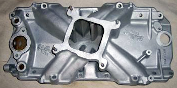
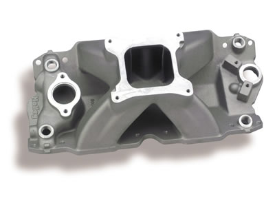
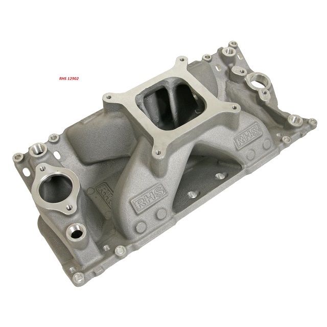
If I remember correctly the ignition is set to run at a max of about 6000rpm, and your running a hydraulic cam thats not likely to make great power over about 6200rpm, thus the AIR GAP is very likely to prove to be a better match! than the single plane intake,
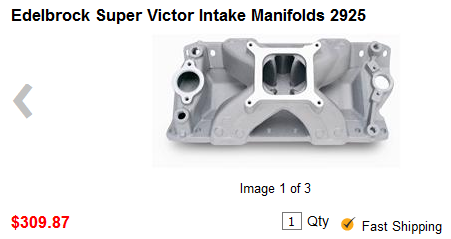
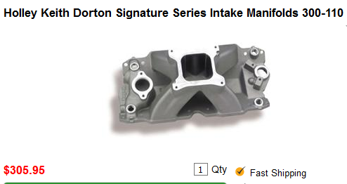
as a general rule you'll find single plane intakes on a SBC generally work best on engine combos with at least a 245 duration cam at .050 lift and with 10.7:1 or higher compression and solid lifter cams that can operate efficiently in the 5500rpm-7000rpm PLUS power band and geared to operate in that same 5500rpm-7000rpm PLUS power band most of the time.
this also requires a short block assembly designed to operate in that upper rpm band, now as the engine displacement is increased, like in the larger displacement BBC engines port and runner air flow speeds will also increase so the effect is that a larger BBC engine can use more, or longer cam duration at a given rpm band, due to its larger cylinder volume to valve curtain area requiring more time, for effective cylinder fill and scavenging .
thus a 2.02 valve sbc reaches max flow near .505 lift
thus a 2.19 valve BBC reaches max flow near .5475 lift
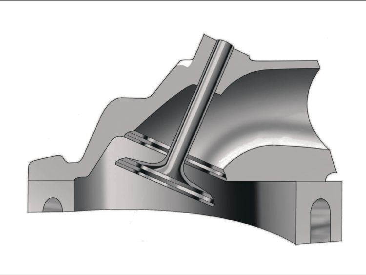
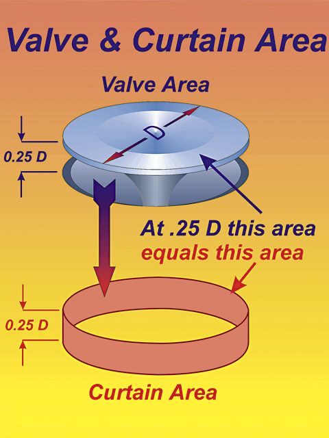
Calculating the valve curtain area
The following equation mathematically defines the available flow area for any given valve diameter and lift value:
Area = valve diameter x 0.98 x 3.14 x valve lift
Where 3.14 = pi (π)
For a typical 2.02-inch intake valve at .500-inch lift, it calculates as follows:
Area = 2.02 x 0.98 x 3.14 x 0.500 = 3.107 square inches
For a typical 2.19-inch intake valve at .550-inch lift, it calculates as follows:
Area = 2.19 x 0.98 x 3.14 x 0.550 = 3.714 square inches
a typical 383 sbc with that .500 lift cam, has 47.875 cubic inches of volume in a single cylinder, divide that by the curtain area of 3.107 and you get 15 cubic inches of cylinder volume for each square inch of valve curtain
a typical 496 BBC with that .550 lift cam, has 62 cubic inches of volume in a single cylinder, divide that by the curtain area of 3.714 and you get 16.69 cubic inches of cylinder volume for each square inch of valve curtain, or about 11% less available air flow even with the larger valve and higher lift cam, to compensate use of a tighter LCA is frequently used to allow a longer, and more effective cylinder scavenging time frame in the big block combo

that questions a bit like asking how good a girl might be in bed based on the color of her hair brush, yes theres a mathematical formula , in fact several, but theres a whole bunch of factors that determine the results, like cam timing, compression,cylinder head flow, back pressure,engine displacement , header primary and collector length and diameter,exhaust temps,etc.
the more back pressure the exhaust system beyond the header collectors has the less effective the headers will be, but if you have a low restriction exhaust and a ram tuned intake with a matched cam timing, a tuned header can in some cases produce gains in excess of 60 hp.
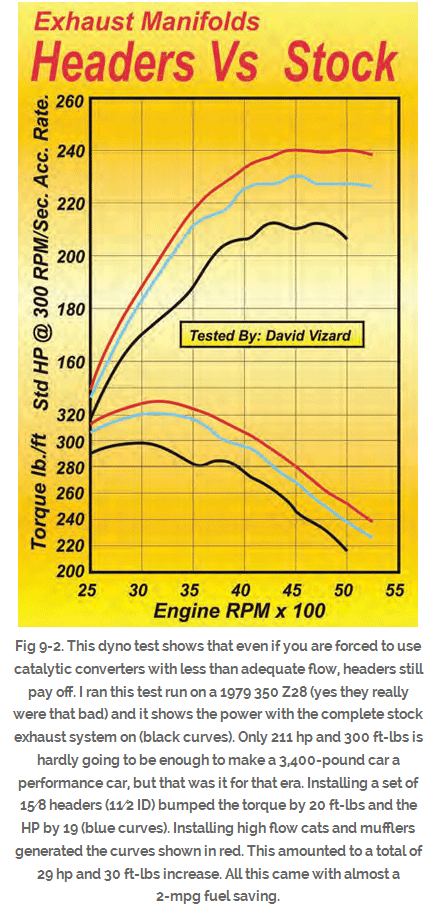
as a general rule Id say your safe expecting a 25-40 hp increase in peak hp from good long tube tuned headers over stock cast iron exhaust manifolds that come on most passenger cars, but with properly matched components on a high compression engine more can be gained.
READ THESE
http://victorylibrary.com/mopar/header-tech-c.htm
http://forum.grumpysperformance.com/viewtopic.php?f=56&t=495&p=613#p613
http://forum.grumpysperformance.com/viewtopic.php?f=56&t=1303
viewtopic.php?f=56&t=572&p=35352&hilit=rams+horn#p35352
http://forum.grumpysperformance.com/viewtopic.php?f=56&t=185
http://www.chevydiy.com/chevy-small-block-engine-guide-exhaust-systems/
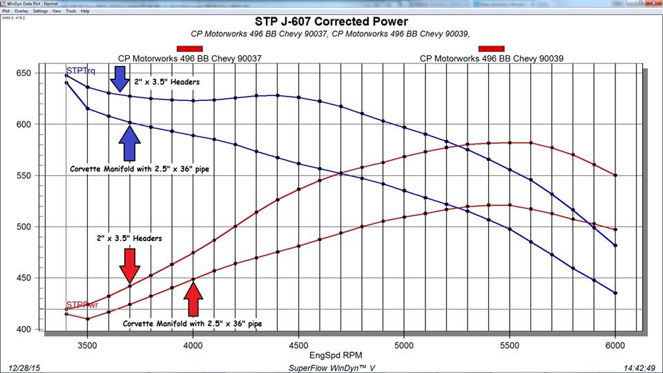
I find this graph very useful, it shows stock corvette exhaust manifolds vs headers on the same 496 BBC engine dyno test
http://garage.grumpysperformance.com/index.php?threads/port-speeds-and-area.333/
http://garage.grumpysperformance.co...alves-and-polishing-combustion-chambers.2630/
http://garage.grumpysperformance.co...lsa-effects-your-compression-torque-dcr.1070/
http://www.enginebasics.com/Advanced Engine Tuning/Intake Runner Length.html
as a general rule you'll find single plane intakes on a SBC generally work best on engine combos with at least a 245 duration cam at .050 lift and with 10.7:1 or higher compression and solid lifter cams that can operate efficiently in the 5500rpm-7000rpm PLUS power band and geared to operate in that same 5500rpm-7000rpm PLUS power band most of the time.
this also requires a short block assembly designed to operate in that upper rpm band, now as the engine displacement is increased, like in the larger displacement BBC engines port and runner air flow speeds will also increase so the effect is that a larger BBC engine can use more, or longer cam duration at a given rpm band, due to its larger cylinder volume to valve curtain area requiring more time, for effective cylinder fill and scavenging .
thus a 2.02 valve sbc reaches max flow near .505 lift
thus a 2.19 valve BBC reaches max flow near .5475 lift
Calculating the valve curtain area
The following equation mathematically defines the available flow area for any given valve diameter and lift value:
Area = valve diameter x 0.98 x 3.14 x valve lift
Where 3.14 = pi (π)
For a typical 2.02-inch intake valve at .500-inch lift, it calculates as follows:
Area = 2.02 x 0.98 x 3.14 x 0.500 = 3.107 square inches
For a typical 2.19-inch intake valve at .550-inch lift, it calculates as follows:
Area = 2.19 x 0.98 x 3.14 x 0.550 = 3.714 square inches
a typical 383 sbc with that .500 lift cam, has 47.875 cubic inches of volume in a single cylinder, divide that by the curtain area of 3.107 and you get 15 cubic inches of cylinder volume for each square inch of valve curtain
a typical 496 BBC with that .550 lift cam, has 62 cubic inches of volume in a single cylinder, divide that by the curtain area of 3.714 and you get 16.69 cubic inches of cylinder volume for each square inch of valve curtain, or about 11% less available air flow even with the larger valve and higher lift cam, to compensate use of a tighter LCA is frequently used to allow a longer, and more effective cylinder scavenging time frame in the big block combo
Junkman2008 said:Hey Grumpy, you always hear that headers give you more horsepower. How does that work and what formula can you use to determine the horsepower gain that a given set of headers may bring?
that questions a bit like asking how good a girl might be in bed based on the color of her hair brush, yes theres a mathematical formula , in fact several, but theres a whole bunch of factors that determine the results, like cam timing, compression,cylinder head flow, back pressure,engine displacement , header primary and collector length and diameter,exhaust temps,etc.
the more back pressure the exhaust system beyond the header collectors has the less effective the headers will be, but if you have a low restriction exhaust and a ram tuned intake with a matched cam timing, a tuned header can in some cases produce gains in excess of 60 hp.
as a general rule Id say your safe expecting a 25-40 hp increase in peak hp from good long tube tuned headers over stock cast iron exhaust manifolds that come on most passenger cars, but with properly matched components on a high compression engine more can be gained.
READ THESE
http://victorylibrary.com/mopar/header-tech-c.htm
http://forum.grumpysperformance.com/viewtopic.php?f=56&t=495&p=613#p613
http://forum.grumpysperformance.com/viewtopic.php?f=56&t=1303
viewtopic.php?f=56&t=572&p=35352&hilit=rams+horn#p35352
http://forum.grumpysperformance.com/viewtopic.php?f=56&t=185
http://www.chevydiy.com/chevy-small-block-engine-guide-exhaust-systems/
I find this graph very useful, it shows stock corvette exhaust manifolds vs headers on the same 496 BBC engine dyno test
http://garage.grumpysperformance.com/index.php?threads/port-speeds-and-area.333/
http://garage.grumpysperformance.co...alves-and-polishing-combustion-chambers.2630/
http://garage.grumpysperformance.co...lsa-effects-your-compression-torque-dcr.1070/
http://www.enginebasics.com/Advanced Engine Tuning/Intake Runner Length.html
Last edited: