76 L82 Corvette 355 engine build questions

I know, I know Indy, I need to measure, and I definitively will. I'm just trying to form a plan and do some of the legwork now so it's not so much when I'm ready to buy parts.

Thanks for the info on the Weiand. It does look like the one I need but I'll call them to be sure. The way they word it is a bit misleading. My 76 is in the 55-86 range obviously but it doesn't have aluminum heads stock, it has the old 882 heads. So I guess they mean only the 87 up corvettes had the aluminum heads stock.

Yeah I'm not going to worry a whole lot about the not2fast number. Several other DCR calculators you guys have given me show I should have about a 157 psig gauge reading which would be about a 171.7 actual cylinder pressure.

I have considered using a thinner head gasket but it just scares me a bit. I'm going to check clearances but I don't want to be on the edge so I'm worrying about it all the time. I have read several places that say 0.060" quench is about the max without getting into detonation so I'm good from that perspective. There are so many different opinions everywhere it's hard to pick and choose. You guys here seem to be some of the most knowledgeable though.
My DCR would be excessive nor would my SCR plus I plan on routing in some cooler air to the carb and using a cool thermostat to help fend off detonation as well so maybe my quench doesn't have to be the absolute minimum?

I would like about a 0.032" thick gasket but the only ones I've found so far are copper which I'm unsure about and most require O-ringing or Cometic which I've read require a specific finish and are really expensive. I'll keep looking.
 
76GrayVette said:
I know, I know Indy, I need to measure, and I definitively will. I'm just trying to form a plan and do some of the legwork now so it's not so much when I'm ready to buy parts.
Ok ....let me see if I understand you correctly, you are saying that I'm
BeatDeadHorseAnim.gif
:lol:


I would like about a 0.032" thick gasket but the only ones I've found so far are copper which I'm unsure about and most require O-ringing or Cometic which I've read require a specific finish and are really expensive. I'll keep looking.

Grumpy uses a copper head gasket without the o-ring, he just uses the Permatex 80697 "Copper Spray-A-Gasket". Read the link below.

viewtopic.php?f=52&t=4403&p=26317&hilit=+copper+spray+#p26317

 
Haha, I guess you could put it that way Indy, but I do appreciate the warnings. :D

Doing a bit more reading and a thought occurred to me.
Let's say I did have a deck height of 0.013" and used a 0.028" thick gasket for the 0.041" quench.
Piston to head should be okay according to you guys, and a lot of other people, but what about piston to valve? I know they are supposed to have about 0.100" clearance so the question is do you guys think Id run into problems with the 0.041" quench? What are some excessive specs to watch out for?

I know there are several factors that influence this and I will measure. I just don't want to buy a cam, put it in and then find out I have problems, if all that can be avoided.

Thanks in a advance guys, you all have been very helpful so far and I appreciate it
 

Now I have not built hundreds of engines, so I can only speak about the
one I posted about on this forum. I'm using a Crower 00471 hydraulic roller
with a .550/.560 inch lift, when I checked there was easily enough
clearance. I checked in a couple of different ways and both times I had
nothing to worry about. I'm also using flat top pistons with 5cc valve reliefs.

You can draw your own conclusions about your situation.

Below is the checking PTVC that I performed.
It continues onto the next page.

viewtopic.php?f=69&t=3814&p=18700&hilit=+valve+lift+error+would+#p18700


Attachments

  • Crower_HR_00471_555_560.JPG
    Crower_HR_00471_555_560.JPG
    81.6 KB · Views: 30
Thanks Indy, that makes me feel better.

Another quick question.

On Cranes website their cam card for the 266 shows an intake closing point of 62 but several calculators show a closing point of 58. Should I be worried or just trust cranes spec card?

The 272 is also different. The card shows 65 but I've calculated 66. Not a big difference but still.

Any thoughts or am I being daft and forgetting something? They don't have posted ICL numbers for the cams so I could be using the wrong numbers there.
 
76GrayVette said:
Thanks Indy, that makes me feel better.

Another quick question.

On Cranes website their cam card for the 266 shows an intake closing point of 62 but several calculators show a closing point of 58. Should I be worried or just trust cranes spec card?

The 272 is also different. The card shows 65 but I've calculated 66. Not a big difference but still.

Any thoughts or am I being daft and forgetting something? They don't have posted ICL numbers for the cams so I could be using the wrong numbers there.

you really won,t know the true cam specs till you dial in the cam, with a degree wheel and dial indicator ETC. and a change in the listed specs of only couple degrees will seldom result in a huge effective change, in your results.
what you do want to verify is that the duration and lift and LSA are at least close to the listed specs, and if they are within a few degrees i would not panic, CRANE,CROWER and ERSON , have been fairly consistent on producing cams that check out close to the listed specs

READ THRU THESE LINKS

viewtopic.php?f=52&t=90

viewtopic.php?f=52&t=181&p=215&hilit=degree+wheel#p215
 
76GrayVette said:
Thanks Indy, that makes me feel better.

Another quick question.

On Cranes website their cam card for the 266 shows an intake closing point of 62 but several calculators show a closing point of 58. Should I be worried or just trust cranes spec card?

The 272 is also different. The card shows 65 but I've calculated 66. Not a big difference but still.

Any thoughts or am I being daft and forgetting something? They don't have posted ICL numbers for the cams so I could be using the wrong numbers there.

Don't worry about how many questions you ask, we love to help!

I'm having trouble making sense of Crane's numbers also. Maybe Grumpy can straighten us out!

When I plug in the numbers from the cam card for rows 2 thru 5, my calculated numbers for rows 6 thru 9 agree with the cam card, but the numbers for Intake Centerline and Exhaust Centerline (rows 10 & 11) are both off by 4°.

The Lobe Separation Angle (LSA), I did in my head, but that's easy. Add Intake Max Lift(105) plus Exhaust Max Lift (115) and divide by two. Like this .... LSA = (105 + 115) / 2 = 110°

The advance was a matter of putting in the right number, but even that does not agree if I try to calculate it.
Advance = LSA - ICA = 110 - 105 = 4°

I'm guessing that the lobes are NOT SYMMETRICAL, that is the opening side is not a mirror image of the closing side of the lobe. Therefore you have to go by what Crane tells you. If that's true, then that's why everyone has slightly different numbers that you are seeing 76GrayVette.


If the lobes are truly not symmetrical, then the only way you can degree the cam, is by using Crane's numbers at 0.050 inches. The method using the Intake Centerline will not work.


Attachments

  • Crane_SH_10004_440_440.JPG
    Crane_SH_10004_440_440.JPG
    91.5 KB · Views: 16
  • Crane_10004_ValveTimingEvents.JPG
    Crane_10004_ValveTimingEvents.JPG
    67.8 KB · Views: 16
Indycars said:
Don't worry about how many questions you ask, we love to help!
Thanks Indy! I read all these articles and posts on the internet and it all kind of jumbles up after a while so I have to ask a few questions at a time to try and straighten myself out.

I'm having trouble making sense of Crane's numbers also. Maybe Grumpy can straighten us out!

When I plug in the numbers from the cam card for rows 2 thru 5, my calculated numbers for rows 6 thru 9 agree with the cam card, but the numbers for Intake Centerline and Exhaust Centerline (rows 10 & 11) are both off by 4°.

The Lobe Separation Angle (LSA), I did in my head, but that's easy. Add Intake Max Lift(105) plus Exhaust Max Lift (115) and divide by two. Like this .... LSA = (105 + 115) / 2 = 110°
So for the Intake Centerline you're getting 105 as well? That's what I first got but it creates a different intake closing point than the card which is what confused me.

The advance was a matter of putting in the right number, but even that does not agree if I try to calculate it.
Advance = LSA - ICA = 110 - 105 = 4°

I'm guessing that the lobes are NOT SYMMETRICAL, that is the opening side is not a mirror image of the closing side of the lobe. Therefore you have to go by what Crane tells you. If that's true, then that's why everyone has slightly different numbers that you are seeing 76GrayVette.


If the lobes are truly not symmetrical, then the only way you can degree the cam, is by using Crane's numbers at 0.050 inches. The method using the Intake Centerline will not work.

[/size][/color]

So that's what has me a bit worried. With the 266 having an intake centerline of 105, then the intake valve closes at 58 while if the ICL is 109 the valve closes at 62. That's a pretty big change in my DCR calculations. It makes me feel like I need a step up in cam size, like maybe the crane 272.
 
76GrayVette said:
So that's what has me a bit worried. With the 266 having an intake centerline of 105, then the intake valve closes at 58 while if the ICL is 109 the valve closes at 62. That's a pretty big change in my DCR calculations. It makes me feel like I need a step up in cam size, like maybe the crane 272.

NO, I don't think you get what I'm saying. It will be tomorrow before I can come up with an illustration to show you what I mean. Bottom line, if you install the cam per Crane's instructions, then the valve should close at 62° ABDC.

But many of my statements depend on if I'm right about the lobe NOT being symmetrical. See you tomorrow!


Most cam lobes are symmetrical, therefore the centerline and max lift are the same number of degrees for each lobe. So when you look at the cam card for the Crane 10004, you can't calculate the lobe centerlines in the normal way. To calculate the centerline (half way between open and closed), we would use the duration and divide by 2, then subtract the degrees from open(Intake) or closed(Exhaust). So for our camshaft from Crane ...

ICL = (266 / 2) - 24 = 109°
ECL = (266 / 2) - 22 = 111°

These are exactly the numbers I get on rows 10 & 11 above for the Intake Centerline and Exhaust Centerline.


How about it Grumpy, is the lobe symmetrical or not ???


Attachments

  • Asymmetrical-Lobe01.jpg
    Asymmetrical-Lobe01.jpg
    14.4 KB · Views: 5
Just to be absolutely certain I was not going to give you the incorrect info ,
because I was sure I had an almost 100% sure ,answer having been down this road as they say,
I was about to post what would have been the correct explanation,....but just to be sure! , I called CRANES tech dept and talked to Craig,
just to verify what I thought was happening and ,
found your correct!
the cam lobes are NOT symmetrical ,as they are designed to maximize valve train stability, and while a rapidly opening valve is desirable to maximize flow rates crane found that a bit slower close ramp rate tends to avoid valve bounce on re-seating so the close ramp rates purposely a bit slower and more controlled to avoid higher rpm valve train stability issues
crane cams is well known for putting a good deal of thought and research time into maintaining valve train durability and stability, and while that might occasionally result in a couple less peak horse power compared to some competitors it also surely results in far fewer broken valve train components and less valve train stress
 

Another clue was the term "Max Lift" on the cam card, no mention of a centerline.

I re-arranged the drawing so that the opening side would be quicker and the closing side slower per your explanation. The dotted line represents a symmetrical lobe shape for comparison.


Attachments

  • Asymmetrical-Lobe01.jpg
    Asymmetrical-Lobe01.jpg
    15.4 KB · Views: 28
Thanks a bunch guys!
So with the asymmetrical lobe, the intake valve closes at 62 degrees because of the slower closing ramp, even though the cam has relatively short duration and other very similar cams have a sooner intake valve closing point with the same duration?
Just want to make sure I'm understanding correctly.
 
Great!

I just got my dial indicator kit in from Summit a little while ago so I can finally check my deck height on Monday when I don't have school or work.

Then maybe I'll finally be able to make a decision on which cam to get. If everything measures out how I've been thinking it will, I'll probably go with the Crane 266.

What do you guys think?
 
76GrayVette said:
Forged steel crank (turned 0.010'')
Stock 5.7 rods (supposed to be forged)

In your very first post you said you had forged rods, but it doesn't sound like you were really sure. You can tell for sure by looking for the line created by casting mold halves where the two halves of the mold come apart. Same holds true for the crankshaft.


I'm running a engine simulation using my DynoSim5 program and will post graphs if it will help. To confirm, let me know what heads you are most likely to use and if you know the flow numbers that will help. I might already have them, so let me know what heads you are thinking about first.

Also your two most likely cams. I have already entered the specs for the Crane 10004. If you really have forged rods and only going to turn the engine at most 5500 RPM, then you shouldn't have any durability problems.

Sorry, I have to make this disclaimer ...... If you checking, measure and adjust all clearance to eliminate all problems, then durability will be great. :D


Attachments

  • SBC_CastRod.jpg
    SBC_CastRod.jpg
    24.7 KB · Views: 17
I don,t advise reuse of any OEM small block connecting rods simply because the cost of far stronger aftermarket connecting rods , that are generally stronger and far less expensive, are easily available.

I don,t know of ANY machine shop that will install the stronger ARP rod bolts then re-size the OEM connecting rods and rebalanced the rods for under $150, and if you want the connecting rods polished and magna flux checked your looking at $350 or more and even if they did in most cases your stuck using 3/8" bolts in comparatively weak connecting rods , because the stock rods are not designed for the larger 7/16" diameter rod bolts that are easily 200% stronger than the OEM 3/8" bolts,that you still need to use with a rotating assembly that needs to be rebalanced,so even without re balancing your looking at about $250 -$350 for used rods that in most cases have had many years of accumulated stress, and were only about 40%-60% as strong as AVERAGE EVEN ON A MILD BUILD, or REBUILD, the cost of the far stronger aftermarket 4340 connecting rods with 7/16" rod bolts that don,t cost a great deal more, than a simply rebuild and instalation of ARP rod bolts on the stock weak connecting rods, makes a great deal of sense simply because they are one the most highly stressed components and doubling the strength over the stock component makes the engine less likely to fail.
EXAMPLE

http://www.adperformance.com/index.php? ... cts_id=516

http://www.adperformance.com/index.php? ... cts_id=241

http://www.summitracing.com/parts/sca-2 ... /overview/
IVE HAD GOOD RESULTS WITH THESE SBC CONNECTING RODS

RELATED INFO)

http://www.summitracing.com/parts/sca-6600021/overview/

viewtopic.php?f=53&t=204

viewtopic.php?f=53&t=9320

viewtopic.php?f=53&t=341

viewtopic.php?f=53&t=510

viewtopic.php?f=53&t=6909

viewtopic.php?f=53&t=852

viewtopic.php?f=53&t=2727

viewtopic.php?f=53&t=247
 
Well, I guess I have some decision making to do. I didn't plan on getting new rods because of the added cost of the rods themselves plus balancing, which I guess is necessary especially if I get new rods but probably even with the new pistons I have. I already had my new pistons pressed on the old rods so I'd have to have them taken back off which is more money. I'm already planing on spending more on this engine than I wanted but I don't want my engine to come apart either.

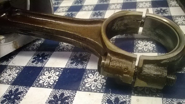
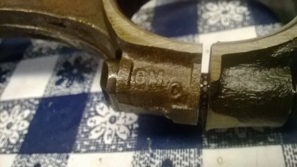
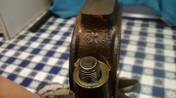
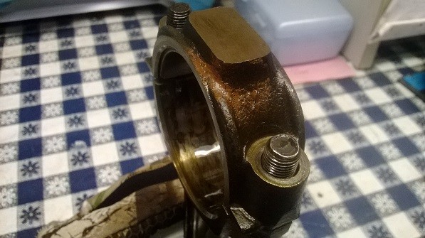
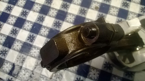
I'll post pictures of the old rods just so you can see them. I've read that the X-rods were used in the L82 Corvettes and were forged. Factory forged rods had a wide casting line like mine do and cast rods had a very thin casting line that was sharp from what I've read. Also, there was some sort of colored stuff, I guess paint, on all the caps so they may be Corvette X-pink rods. I don't know. I guess they aren't as good as aftermarket anyway.

uzd5.jpg

0ivn.jpg

i2m6.jpg

rpbj.jpg

These next two pictures you can see the "paint"
gvup.jpg

aw83.jpg

f9hj.jpg


I do appreciate the warnings and advise grumpy, even though I may not like to hear it. I plan on keeping this car and I want it to last a long time so I know what I should do, it's just a matter of doing it and making my wallet agree.
 
first , congrats on your obvious ability of taking and posting clear pictures as that helps in almost all threads to allow people reading them to get a better grasp on the discussion.

We all make decisions based on what your wallet will allow, now keep in mind that those factory connecting rods have worked and in most cases will continue to work reasonably well in your application, but that's NOT the same thing as being the best choice, and the reason i say that in most cases, is that youll want to have arp rod bolts installed, which are easily 505 or more stronger than the stock connecting rod bolts that have been thru hundreds of thousands of stress cycles and youll want the connecting rods magna-flux checked for cracks and re-sized and balanced, which by the time your done will make the cost equal or exceed the aftermarket connecting rods which are easily 50%-150% stronger (obviously dependent on what you select to use)and is why I generally donate the connecting rods to friends and not reuse them in my SBC engines. Ive found the SCAT connecting rods with 7/16" ARP cap screw style rod bolts to be a bargain.
so the question becomes " would you prefer to spend a bit more and basically have nearly bullet proof connecting rods, or MAYBE,save a few bucks and re-use the reconditioned stock rods" but be aware many of the stronger aftermarket connecting rods are designed for full floating piston pins, and if you use those connecting rods, with full floating piston pins you need to verify the piston pins you use will work with your current pistons.
there ARE aftermarket connecting rods designed for pressed pins that are still noticeably stronger than the original OEM connecting rods, why not call and talk to SCATS tech DEPT.

Phone: 310 370 5501
Fax: 310 214 2285
Hours: 8:00 to 4:45 PT Monday - Friday

http://scatcrankshafts.com/#3
 
Back
Top