76 L82 Corvette 355 engine build questions

wow very sorry to hear about your dad, i know its rough losing family so young and untimely like that. on another note it looks like your build is coming along nicely, i second the motion for the M55A or Z/28 pump, great all around pump since most of the time you are just gonna driving and cruising the car anyway. oh and the steel collar is a given, just one less thing thats likely to go wrong. in the end its just a couple dollars for alot of peace of mind
 
Alright, thanks guys. That's kind of what I thought on the steel retainer.
So, the high pressure M55A or Z/28 pump is basically the same as the standard pump just with the high pressure spring right?

And I read the link on using the windage tray during cam break in. I had been meaning to ask you about that as I had read it should be left out. It should be fine then to put it back in and not worry about it affecting cam break in.
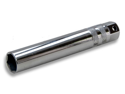
Do you know where I can get a socket long enough to use on the main cap bolts that have the studs for the tray?
 
76GrayVette said:
...
Do you know where I can get a socket long enough to use on the main cap bolts that have the studs for the tray?

ARE THEY 5/8 hex head?
harbor freight sells a DEEP plug socket

esp3.jpg


theres also slide thru sockkets
http://www.harborfreight.com/21-piece-c ... 67974.html
 
So, I got my parts back from the balance shop and I decided to check my main bearing clearances.
They were all right at 0.001" and according to the book I have, that is a little tight.
What do you guys think?

As I said before the crank was turned 0.010" so I was using Clevite bearings, part #MS909P10.
Maybe I should get some 0.009" bearings?
 
I like to Always Micrometer Check all Crankshaft Main & Rod Journals myself.
I have a 0-5 Micrometer set.
Dial bore guages.
Inside micrometer 0-8 inch extensions.
Mike set has accuracy to .0001 inch or 1/10,00 of an inch.
Standards to Calibrate.
Plastic guage my final assembly check.
 
Have a dedicated bearing micrometer with Carbide ball end.
Measures to 50 million of an inch accuracy.
 
87vette81big said:
I like to Always Micrometer Check all Crankshaft Main & Rod Journals myself.
I have a 0-5 Micrometer set.
Dial bore guages.
Inside micrometer 0-8 inch extensions.
Mike set has accuracy to .0001 inch or 1/10,00 of an inch.
Standards to Calibrate.
Plastic guage my final assembly check.

Yeah, that would probably be the best way to go, but I was hoping to get close enough without having to buy all the extra tools since I don't plan on building many if any more engines.

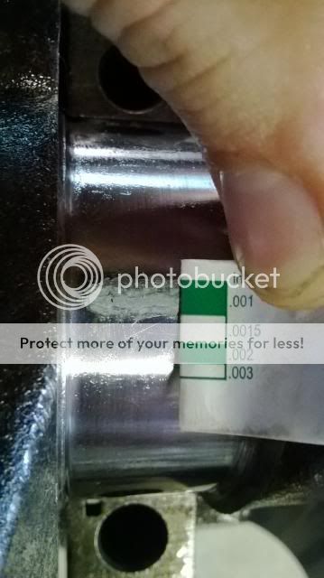
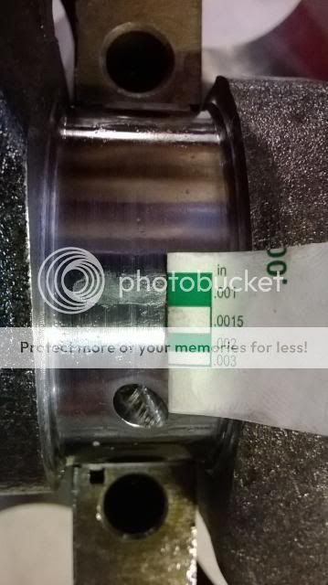
I measured the mains again and got the same thing. Numbers 2,3,4 are 0.001, number 5 is 0.002, and number 1 is 0.0015.
So, numbers 1 and 5 are within spec, but 2,3,4 are bit tight.
Here are a few pictures:
Main #4
bearingclearance1.jpg

Main #3
bearingclearance2.jpg

Main #5
bearingclearance3.jpg

Main #1
bearingclearance4.jpg

I also did Rod #8 and it was a bit tight at 0.001 as well.
bearingclearance5.jpg


Let me know what you guys think. Am I doing it right?
 
http://cleviteonengine.com/askclevite.asp

http://www.jegs.com/p/Clevite/Clevite-7 ... 4/10002/-1

why not call JEGS 800-345-4545

viewtopic.php?f=50&t=1222

and order bearings that have .001-.0015 more clearance

Rod bearings 0.002 - 0.025" , side clearance 0.010 - 0.020"

Main bearings 0.002 - 0.003" for most engines ( 0.020-0.025 bearing clearance on small blocks, .025-.027 bearing clearance is about ideal, on big blocks ), 0.005 - 0.007 crankshaft end play

Stock Bearing Clearances

The general rule of thumb for bearing clearances is 0.0010 inch for every 1 inch of journal diameter. That's true for mains and rods, and applies to almost all engines. For the small-block's 2-inch rod journals, that means 0.002 inch of clearance between the rod journal and bearing, by the rule of thumb. The GM-specified tolerances are 0.002 to 0.0025 inch, which lines up well with the rule. Side clearances come in at 0.010 to 0.020 inch, as specified by GM. The clearance rule applies to most engines, but it's generally best to avoid going below 0.0020 inch on any bearing, regardless of the journal diameter.

YOU ALSO HAVE THE OPTION OF HAVING THE CRANK JOURNALS MICRO POLISHED WHILE REMOVING JUST ENOUGH SURFACE FROM THOSE JOURNALS TO GAIN THE REQUIRED CLEARANCE, IF THE CLEARANCE IS CURRENTLY TOO TIGHT

viewtopic.php?f=53&t=9955&p=38385&hilit=crank+journal#p38385

viewtopic.php?f=53&t=9214&p=33116&hilit=crank+journal#p33116

WATCH VIDEO most larger machine shops can do that cheaply and gain you the required clearance
http://www.youtube.com/watch?v=mHVzyvszbhw
 
Thanks Grumpy, that's what I thought.

So, you like the Clevite H series then? I've read they won't trap debris as well as the P series and I don't believe they offer a 0.009" undersize P series. What about Sealed power bearings? Anybody use those?
 
76GrayVette said:
Thanks Grumpy, that's what I thought.

So, you like the Clevite H seies then? I've read they won't trap debris as well as the P series and I don't believe they offer a 0.009" undersize PH series. What about Sealed power bearings? Anybody use those?
H series will work on the street. Like you read they won't trap debris.
Designed for Race the H series.
Must use a top notch oil filter system.
I would block off the oil bypass valve. Use MOROSO.
A 2 quart oil filter fits on C3 Vette just fine.
Plenty of grpund clearance. Has no flapper valve.
Full flow design.
 
Another Viable option is to remove the crankshaft.
Let a Competent Machinist polish .0005" -.001 less.
Cant do yourself.
Crank put in a lathe. Crank belt polisher used.
Special crank belt polisher that costs 1K $$.
 
Calco H bearings offer protection & longevity also.
Costs $$.
 
ACL bearing better that clevite.
Long lasting. tested into drag racing engine, same engine same number of runs, ACL show much less wear(if any wear at all).
 
Choice of Manufacturer bearings is Like Blondes, Red Heads, & Burnettes .
What do you like & Prefer ?
The hair on her head may be blonde but what about that other hair down below?
Have to get in & take a look yourself.

When you build a Pontiac 455 no H bearing made for the Mains.
Just the Rods.
H 455 mains been gone since 1996.
I use Vandervell Indium Lead Mains & Rods.
Hard to find.
I stocked up all standard 3-1/4 & 3 " mains & rods & all undersizes.
 
I've been checking my deck height or how far my piston is in the hole the last couple days and I think I finally got good measurements but I don't like the numbers.
I checked all four corners by finding top dead center with my dial indicator and then used several different strait edges with two sets of feeler gauges to make sure I got accurate, consistent measurements.
Each corner is a different though. I used the same rod and piston so that can't be the cause.
#7=0.015" #1=0.018"
#8=0.013" #2=0.010"
Now I was expecting them to all be 0.013" because the machine shop said they took off 0.012" but it looks like they got sloppy.
My question is, will this cause a problem? I feel that it would but I wanted to double check with you guys before taking it somewhere to have it fixed.
 
"WILL IT CAUSE A PROBLEM"
well the answer of course depends a great deal on what your expectations are and how precise you expect the details of your engine build to be!
your dealing with several factors., like has the block been decked both parallel too the crank bore access and level and at the proper angle on both sides
block deck height
viewtopic.php?f=53&t=3759
piston pin height
viewtopic.php?f=53&t=5064&p=35026&hilit=piston+pin+height#p35026

the first thing Id point out is these always some variation in the center to center distance on every connecting rod and piston to pin deck measurement so swapping pistons on connecting rods and locations of the rod and piston combos in the block , this is one reason I almost always prefer full floating piston pins and pistons as they allow rods to be swapped between cylinders, as you check pre-assembly clearances, and its also why you tend to balance each piston and rod individually.
I,d start by checking the block deck corner to crank center-line measurements on each bank, and only then proceed to the piston deck heights
I,m sure theres been hundreds of thousands of engines assembled with even worse clearances, but its an invitation to problems best avoided by carefully checking and minimizing those clearances


related threads that should be read

viewtopic.php?f=53&t=3760&p=9968&hilit=piston+pin+height#p9968

viewtopic.php?f=50&t=501&p=9050&hilit=piston+pin+height#p9050

viewtopic.php?f=52&t=399&p=21603&hilit=piston+pin+height#p21603

viewtopic.php?f=51&t=5460&p=16311&hilit=piston+pin+height#p16311

viewtopic.php?f=52&t=2077&p=5565&hilit=ccing+heads#p5565

viewtopic.php?f=52&t=2630&p=21649&hilit=polishing+combustion#p21649

viewtopic.php?f=53&t=726&p=9291&hilit=piston+pin+height#p9291
 
Right, thanks Grumpy, I'll check the deck to crank center line measurements before proceeding.
But, I have to ask, is it at all possible or practical to use two different thickness head gaskets?
Say a 0.028" on the high side and a 0.030" on the low side. It would even out my quench distances and intake mating points by quite a bit. I mean the engine isn't going to know the difference right? As long as they are the same type gasket?
 
use of two different head gasket thicknesses,one , different on each deck, is not all that rare ,as a stop gap fix for similar problems, but of course the correct route is correctly machining the block dimensions and verifying clearances, and matching the individual component placement to minimize the variations.
the difference between assembling an engine and BUILDING an engine is knowing what your trying to do and actually doing it, and when you find an issue preventing that from, matching the intended specifications and clearances , occurring you stop and back track,you make a judgement call on how important the variation you find in the specs are,and decide if that part needs to be re-machined or needs to be replaced to get the proper machine work or clearances done,or fitted or its a small enough variation that it can be ignored or compensated for, this , measuring and verifying process is why properly building an engine is so much more expensive than just buying components and slapping them together with the matching sealants and gaskets.
Its also very time consuming and frequently requires several repeat trips to a machine shop, so finding a decent machine shop is critical, as is knowing how to verify the work they do at each step has been done correctly, so you as the builder obviously need some precise measuring tools


viewtopic.php?f=50&t=10031&p=38952&hilit=precision#p38952

viewtopic.php?f=59&t=1390&p=3073&hilit=precision#p3073

viewtopic.php?f=52&t=90

viewtopic.php?f=52&t=399

viewtopic.php?f=53&t=852

viewtopic.php?f=53&t=2726

viewtopic.php?f=53&t=247

viewtopic.php?f=53&t=509
 
Right, so what all does the machine shop usually need to shave a block to a certain height?
Just the block or do they need the crank and pistons as well?
And does it matter that the cam bearings are already installed?
 
Back
Top